Table of Contents
Advertisement
Quick Links
Advertisement
Table of Contents

Related Manuals for Alcatel 7750 SR-12


Summary of Contents for Alcatel 7750 SR-12
- Page 1 7750 SR-12 NSTALLATION UIDE Document Part Number: 93-0019-01 December 2003...
- Page 2 No portion of this document may be reproduced in any form or means without prior written permission from Alcatel. Information in this document is proprietary and confidential to Alcatel. The information in this document is subject to change. All trademarks and registered trademarks are the property of the respective owners.
-
Page 3: Table Of Contents
7750 SR-12 System Installation Process ........ - Page 4 Removing the Air Filter Tray ............120 Page 2 7750 SR-12...
- Page 5 Index ............... 155 Page 3 7750 SR-12...
- Page 6 Table of Contents Page 4 7750 SR-12...
- Page 7 7750 SR-12 AC Power Supply LED Descriptions ........
- Page 8 10/100 Management Ethernet Port - RJ45 Female ........153 Page 6 7750 SR-12...
- Page 9 7750 SR-12 AC Power Rectifier (Example) ....... . . 28...
- Page 10 Figure 51: Port Types............150 Page 8 7750 SR-12...
-
Page 11: Preface
AC power can be converted to DC power using external AC power rectifiers available from Alcatel. Instructions to wire AC power shelves and AC power rectifiers to the DC PEMs are provided. AC rectifiers and AC power shelves are available from Alcatel and are packaged and shipped separately. -
Page 12: Table 1: Information Symbols
Note This symbol provides additional operational information. Class 1 laser products are listed in the MDA installation guides. Only approved Class 1 replaceable laser transceivers should be used with this product. Class 1 Laser Product Page 10 7750 SR-12... - Page 13 ECHNICAL UPPORT If you purchased a service agreement for your 7750 SR-12 router and related products from a distributor or authorized reseller, contact the technical support staff for that distributor or reseller for assistance. If you purchased an Alcatel service agreement, contact technical...
- Page 14 Page 12 7750 SR-12...
-
Page 15: 7750 Sr-12 Overview
7750 SR-12 O VERVIEW HAPTER This chapter introduces the Alcatel 7750 SR-12 router and provides an overview of the following topics: • Chassis Features on page 14 → 7750 SR-12 Modules on page 19 − SF/CPMs on page 19 •... -
Page 16: Chassis Features
SF/CPM operates in standby mode and takes over system operation if the primary fails. The 7750 SR-12 provides access to components from both the front and back sides. The filter tray, SF/CPMs, IOMs, and MDAs are accessed from the front of the chassis. The power entry modules (PEMs) and cooling trays (impeller trays) are accessible from the chassis rear. -
Page 17: 7750 Sr-12 Overview
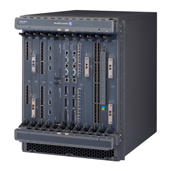
7750 SR-12 Overview SR12001B Figure 1: 7750 SR-12 Chassis Front View Page 15 7750 SR-12... -
Page 18: Table 2: Chassis Front View Features
Table 2: Chassis Front View Features Description Cable management system Chassis slot numbers MDA (installed) Full slot panel blank SF/CPM MDA blank panel Rack mounting brackets Air vent ESD plug Compact flash slots Compact flash slot 3 (cf3:) Page 16 7750 SR-12... -
Page 19: 7750 Sr-12 Overview
7750 SR-12 Overview Figure 2 displays the 7750 SR-12 rear view. Refer to Table 3 for key descriptions. SR12002B Figure 2: 7750 SR-12 Chassis Rear View Page 17 7750 SR-12... -
Page 20: Table 3: Chassis Rear View Features
RTN studs for DC power cable Safety cover OFF/ON DC switch Impeller (fan) tray faceplate DC PEMs. The top slot is referred to as PEM Slot 1. The lower slot is referred to as PEM Slot 2. DB-25 connector (status) Page 18 7750 SR-12... -
Page 21: 7750 Sr-12 Modules
MDAs on page 25 SF/CPM The SF/CPM(s) control the routing and switching functions for the entire 7750 SR-12 system. The router operates with a minimum of one SF/CPM which must be installed in either center slot A or The SF/CPM connects directly to the backplane and carries traffic between line cards. The backplane provides high-speed access to the SF/CPMs, IOMs, and MDAs. -
Page 22: Table 4: Model Sfm-400G Sf/Cpm Field Descriptions
• Green: Locked (operational state) • Green (blinking): Clock in (internal) holdover state • Amber: Alarm condition • Amber (blinking): Clock in free running state • Unlit: Clock not initialized or no SONET ports are provisioned on the system. Page 20 7750 SR-12... - Page 23 7750 SR-12 Overview Table 4: Model SFM-400G SF/CPM Field Descriptions (Continued) Label/Part Sub- Description category Reference The Reference LEDs are lit only on the active CPM and indicate the status and quality of the individual timing sources. • Green: Qualified and selected as clock reference input.
- Page 24 Alarm The Alarm port is provisioned as a DB-9 serial port and is used to connect to external alarm devices that report conditions that trigger red or amber alarms. Page 22 7750 SR-12...
- Page 25 7750 SR-12 Overview Table 4: Model SFM-400G SF/CPM Field Descriptions (Continued) Label/Part Sub- Description category ACO/LT The Audible Alarm Cutoff/Lamp Test button verifies the operability of LEDs. When pressed, the LEDs should temporarily illuminate. This button also turns off all external alarm relay control bits until the next new alarm condition.
-
Page 26: Synchronization In Redundant Systems
EDUNDANT YSTEMS The 7750 SR-12 router is capable of a 1:1 Control Processor Module (CPM) redundancy scheme. Redundancy methods facilitate system synchronization between the active and standby CPMs so they maintain identical operational parameters to prevent inconsistencies in the event of a CPM failure. -
Page 27: Ioms
7750 SR-12 Overview 7750 SR-12 routers support a wide variety of interfaces, including Ethernet, SONET/SDH (channelized and concatenated), and ATM. Each I/O module (IOM) features a single-slot baseboard which can carry up to two hot-swappable MDAs with Small Form-factor Pluggable (SFP) optics, providing outstanding flexibility to mix-and-match interfaces per-slot as customer and network needs dictate. -
Page 28: Chassis Components
OWER EDUNDANCY At least one DC PEM must be installed in the 7750 SR-12 chassis to operate. An additional PEM can be installed for power redundancy. f you need to convert AC power to usable DC power, up to two rectifiers can be installed in the same AC power shelf and connected to a DC PEM. -
Page 29: Table 5: Dc Power Entry Module Features
NTRY ODULES DC PEMs are easily installed and removed from the rear 7750 SR-12 chassis power slots 1 and 2. One PEM can support the full system current requirements if you are operating the SR-12 without power redundancy. For redundancy, two PEMs must be installed and powered on at all times. -
Page 30: Figure 5: 7750 Sr-12 Ac Power Rectifier (Example)
AC-input power shelf. Each AC power shelf should be wired to a separate DC PEM installed in the 7750 SR-12 chassis. A maximum of two AC power shelves can be connected to a chassis when two DC PEMs are installed. -
Page 31: Cooling System
OOLING YSTEM The 7750 SR-12 system is cooled by hot-swappable impeller (fan) trays. A minimum of two impeller trays must always be installed and fully operational while the SR-12 is powered up. A third tray can be installed for redundancy. Each tray houses two impellers. The trays are accessed from the rear of the chassis and are interchangeable in any tray slot. -
Page 32: Air Filter
ANAGEMENT YSTEM The 7750 SR-12 chassis can accommodate 2 optional cable management trays. The trays are mounted on the front of the chassis, above and below the card slots. The cable management system manages the fiber optic cables so they do not interfere with the insertion or removal of IOMs and MDAs and prevents sharp bends which can damage the cable or degradate performance. -
Page 33: Component Operating Requirements
Only used for AC-to-DC power conversion. There is a 1:1 ratio of AC power shelf to DC PEM installed in an 7750 SR-12 chassis. A maximum of two DC PEMs can be installed in an SR-12 chassis, thus, only two AC power shelves can be used for the AC to DC conversion. -
Page 34: 7750 Sr-12 System Installation Process
7750 SR-12 System Installation Process 7750 SR-12 S YSTEM NSTALLATION ROCESS To install the 7750 SR-12 system, perform the installation procedures in the following order: Step 1 Prepare the site. Step 2 Unpack the chassis and components. Step 3 Rack mount the chassis. -
Page 35: Site Preparation
REPARATION HAPTER This chapter provides information about preparing your site to install a 7750 SR-12 router. This chapter provides an overview of the following topics: • Warnings and Notes on page 34 • System Specifications on page 35 → Chassis Specifications on page 35 →... -
Page 36: Warnings And Notes
• Maintain adequate air flow to and from all equipment in the rack that might interfere with the normal flow of cooling air through the router. • The 7750 SR-12 router includes factory installed rack mounting brackets to install in a 19- inch equipment rack. -
Page 37: System Specifications
Operating: Temperature 32 to 122 degrees ºF (0 to 50ºC) Maximum altitude 10,000 ft./3,048 m Relative humidity 5 to 90% (non-condensing) Heat dissipation (worst 3000 watts (joules/sec) case configuration) 10,237 BTU/hour Acoustic noise level 67.0 dBA Page 35 7750 SR-12... -
Page 38: Power Module Specifications
Using 3 Tyco NP1200 AC power rectifiers: Input 100;120V/200-240V; 50/60Hz 15A; 12A/7.4A Output 48-56V Using 2 Tyco NP2500 AC power rectifiers: Input 170-264V 14A @ 208V 13A @ 240V Output 42-58V Using centralized DC: Input -48V/-60VDC 75/60A Page 36 7750 SR-12... -
Page 39: Mda Specifications
Site Preparation MDA S PECIFICATIONS Table 12: MDA Specifications Parameter Description Dimensions 0.5" H x 6.75" W x 7" D Weight 1 lb. Page 37 7750 SR-12... -
Page 40: Component Power Consumption
System Specifications OMPONENT OWER ONSUMPTION Table 13: Power Consumption Component Conservative Estimate (Approx. 20% margin) (Watts) Chassis (low RPMs) Chassis (high RPMs) SF/CPM MDAs: M1-10GB M10-1GB-SFP M60-10/100ETH-TX M20-100ETH-SFP OC-12/STM-4 OC-48/STM-16 OC-192/STM-64 Page 38 7750 SR-12... -
Page 41: Component Specifications
1.4" H x 16.75" W x 17" D Weight: 9 lbs. MDA: Dimensions: 1.4" H x 7.5" W x 7" D Weight: l.5 lb. Impeller tray: Dimensions: 17.5" H x 5.5" W x 7.5" D Weight: 12 lbs. Page 39 7750 SR-12... -
Page 42: The Equipment Rack
• Standard telco rack (four-post) The equipment rack rail mounting holes must align with the mounting holes on the chassis mounting brackets. The 7750 SR-12 mounting brackets are factory installed for a front mount in a 19-inch rack. Required tools: •... -
Page 43: Rack Clearance Requirements
SF/CPM, IOMs, MDAs, and air filter in the front and allow space to remove and install the cooling trays and DC PEMs in the rear. 20” REAR REQUIRED FOR MAINTENANCE REAR FRONT 20” FRONT REQUIRED FOR MAINTENANCE Figure 6: Chassis Clearance Requirements Page 41 7750 SR-12... -
Page 44: Safety Considerations
Safety Considerations AFETY ONSIDERATIONS • Install the 7750 SR-12 in standard sized equipment racks. The SR-12 is shipped with the 19-inch rack mounting brackets installed. • The router should be installed in a clean, dry, ventilated, and temperature-controlled room. •... -
Page 45: Fans
ILTER The air filter tray must always be installed while the 7750 SR-12 is powered up. The air filter is factory installed. Filters should be inspected monthly and cleaned and replaced every twelve months or as required. -
Page 46: Safety Standards/Compliance Agency Certifications
VCCI Class A FCC Part 15 Class A EN55022 Class A EN55024:1998 For information technology equipment ICES-003 Class A CE Declaration Certifications NEBS compliant (in progress) Environmental ETS 300 019-1-X (in progress) ETS 300 753 Acoustic noise Page 44 7750 SR-12... -
Page 47: Installing The 7750
7750 SR-12 NSTALLING THE HAPTER This chapter provides information to rack mount a 7750 SR-12 chassis. This chapter provides information on the following topics: • Unpacking the Chassis on page 46 → Unpacking Precautions on page 46 • Rack Mounting the Chassis on page 51 •... -
Page 48: Unpacking The Chassis
Notes: • The 7750 SR-12 is shipped in a wooden crate and is strapped to a pallet with casters that is used to wheel the router out of the crate and rolled to the equipment rack location. -
Page 49: Installing The 7750
Installing the 7750 SR-12 SR12033 Figure 7: Unfastening the Crate Clips To open the crate: Step 1 Unfasten the clips on the left and right sides of the front panel. See Key 1 Figure Page 47 7750 SR-12... -
Page 50: Figure 8: Opening The Crate
Unpacking the Chassis SR12034 Figure 8: Opening the Crate To unpack the 7750 SR-12 chassis: Step 1 Unfold the front panel downward to act as a ramp. See Key 2 in Figure Step 2 Loosen and remove the wing nuts and washers on the board anchoring the chassis. -
Page 51: Figure 9: Removing The Chassis From The Crate
Installing the 7750 SR-12 SR12035 Figure 9: Removing the Chassis from the Crate To unload the chassis from the crate: The chassis is secured to a pallet that has attached wheels. Carefully roll the chassis and Step 1 pallet down the ramp and maneuver as close to the equipment rack as possible. -
Page 52: Figure 10: Lifting The Chassis
SR12037 Figure 10: Lifting the Chassis Step 1 There are no handles or hand grips on the 7750 SR-12. With at least two people, lift the chassis from the bottom (see Key 7 in Figure 10). Do not put your hands inside the chassis frame to lift. -
Page 53: Rack Mounting The Chassis
Caution: • There are no handles or hand grips on the 7750 SR-12. Lift the router from underneath. Do not lift the router by the internal chassis frame. • When rack mounting the 7750 SR-12 in an equipment rack, do not stack other 7750 SR-12 units or any other equipment directly on top (where the bottom unit is supporting other devices). -
Page 54: Table 17: Rack Mounting The 7750 Sr-12 Chassis
Rack Mounting the Chassis SR12005A Figure 11: Installing the Chassis into an Equipment Rack Table 17: Rack Mounting the 7750 SR-12 Chassis Description Equipment rack Rack mounting screws Rack mounting bracket Page 52 7750 SR-12... - Page 55 With at least two people, or, if necessary, using a hand cart, pallet jack, or forklift, position Step 1 the chassis in front of the rack. With one person in front of the rack and one behind the rack, lift the 7750 SR-12 from the Step 2 bottom and position it in the rack.
-
Page 56: Installing The Cable Management System
The following instructions assume the chassis rack mounting brackets remain in the front- mounting position, as they are shipped from the factory. The cable management trays are shipped with shims screwed into the brackets. Remove the shims if the 7750 SR-12 chassis is front- mounted. -
Page 57: Figure 12: Cable Management System
Installing the 7750 SR-12 SR12026A Figure 12: Cable Management System To install cable management trays on a front rack-mounted 7750 SR-12 chassis: Step 1 Remove the cable management trays from the packaging. The cable management system is shipped with the mid-mount shims attached. Loosen and Step 2 remove the screws which attach the shims to the cable management system. -
Page 58: Making The Chassis Ground Connection
Two grounding screws are located on the rear side of the chassis, on the top left-hand side. Only trained and qualified personnel should install or replace this chassis and Danger: chassis components. Note: When wiring any Alcatel 7750 router, the ground connection must always be made first and disconnected last. REPARING THE ROUND Use #6 AWG for the ground wire connection. - Page 59 Installing the 7750 SR-12 To prepare the ground wire: Using a wire-stripping tool, strip each the insulation from the wire to 7/16-inches. Step 1 Step 2 Slide the open end of the ground lug (accessory box) over the exposed area of the prepared wire.
-
Page 60: Making The Ground Wire Connection
Table 19: Ground Wire Descriptions Description Grounding studs Panduit LCC F6-14A Washer (Use two washers sized to accommodate the 1/4" studs) Nuts (Use two nuts sized to accommodate the 1/4" studs) Ground cable end prepared according to local safety codes. Page 58 7750 SR-12... - Page 61 Installing the 7750 SR-12 To connect the ground cable: Remove the nuts and washers from the ground lugs on the rear side of the chassis, on the Step 1 top left-hand side. Using the prepared ground wire, place the ground lug through the two chassis ground Step 2 screws.
-
Page 62: Installing Impeller Trays
• Three impeller trays are recommended for normal operation. • The trays are hot-swappable. The 7750 SR-12 chassis operates safely while you replace the fan tray for up to approximately five minutes at an ambient temperature of 95° F (35° C). If a longer maintenance time is required, power off the system to prevent overtemperature conditions. -
Page 63: Table 20: Impeller Tray Descriptions
Installing the 7750 SR-12 SR12025A Figure 15: Installing Impeller Trays Table 20: Impeller Tray Descriptions Description Impeller tray Captive screws Page 61 7750 SR-12... - Page 64 Slide the connector end into the slot until it is fully seated. Tighten the captive screws. Step 3 Install second impeller tray in the middle slot. Step 4 Install third impeller tray in the left-most slot. Page 62 7750 SR-12...
-
Page 65: Installing Power Supplies
AC on page 74 → Installing an AC Power Shelf on page 76 → Installing the AC Power Rectifiers on page 77 → Connecting The AC Power Shelf Cables to the DC PEMs on page 77 Page 63 7750 SR-12... -
Page 66: General Power Warnings And Notes
ESD-preventive wrist or ankle strap and always connect an ESD strap to the grounding plug on the front of the chassis. Notes: • The 7750 SR-12 is shipped with two factory-installed DC PEMs. Installation instructions are provided in the chapter. Removal instructions are provided in Appendix B: Field Replaceable Units on page 119. -
Page 67: Installing Dc Pems
• Confirm that the DC power source is OFF during installation. The power source should be a safety extra-low voltage (SELV) source. • The 7750 SR-12 router with DC power entry modules should be installed only in restricted access areas (such as dedicated equipment rooms and electrical closets) in accordance with Articles 110-26 and 110-27 of the most recent National Electrical Code ANSI/NFPA 70. - Page 68 One -48 DC,100A (maximum) branch circuit is required for each PEM. • The 7750 SR-12 requires a minimum of one DC power entry module (PEM) to operate, but two are recommended for redundancy. When two PEMs are installed, they share the electrical load equally as long as both PEMs are operational.
-
Page 69: Installing Adc Pem
Installing Power Supplies DC PEM NSTALLING A SR12012A Figure 16: Installing a DC PEM Table 21: Installing a DC PEM Description Power cable (VDC) Return cable (RTN) Power studs Safety cover I / O (On/Off) switch Page 67 7750 SR-12... - Page 70 Secure into place by tightening the captive screws. Step 6 If you plan to use DC power to operate the 7750 SR-12, proceed to the following steps to Step 7 connect the power cord(s). If you plan to install AC power rectifiers to operate the 7750 SR-12, proceed to...
-
Page 71: Dc-Input Power Wiring
3.965 IN. 0.850 IN. 0.600 IN. 0.740 IN. 1.300 IN. 0.750 IN. SR12032 Figure 17: DC Terminal Block Stud Dimensions and Spacing 0.250 2 Holes 0.750" All measurements in inches. SR12030 Figure 18: DC Terminal Block Lug Page 69 7750 SR-12... -
Page 72: Table 22: Dc Power Cable
Step 2 Locate the lug in the accessory box. Slide the open end of the lug over the exposed area of the prepared wire. Step 3 Using a crimping tool, crimp the lug to the wire. Page 70 7750 SR-12... -
Page 73: Dc Input Terminal Block Wiring
The DC power supply cables attach to the power supply terminal studs. Figure Figure 21, and Figure 22 display DC-input terminal block safety cover and wiring views. SR12016 Figure 20: Removing the DC Terminal Block Safety Cover SR12017 Figure 21: Wiring the DC-Input Power Terminal Block Page 71 7750 SR-12... -
Page 74: Figure 22: Dc-Input Power Terminal Block Wiring With Safety Cover
Connect the VDC (-) cable to the top (-48V) terminal according to local safety codes. Replace the nuts and tighten with a torque wrench to 56 pound-inches. Step 6 Replace the safety cover and secure into place by tightening the captive screws Step 7 (Figure 22). Page 72 7750 SR-12... -
Page 75: Table 23: Dc-Input Terminal Block Descriptions
Installing Power Supplies Figure 23: Installed DC Power Entry Modules Table 23: DC-Input Terminal Block Descriptions Description -VDC Page 73 7750 SR-12... -
Page 76: Ac-Input Power Guidelines
#6 AWG high-strand-count copper wire. If the 7750 SR-12 router is located outside the USA, consult local and national electrical code for proper wire sizing. • The cable must be sized for 80A service to allow for a fully loaded 7750 SR-12 system at 36V input per NEC and local safety codes. - Page 77 If you intend to use AC power rectifiers to convert AC power, observe the following guidelines: • There are no AC power cord receptacles on the 7750 SR-12 chassis. AC power must be converted to usable DC input power by connecting an external rectifier to the terminal studs on the PEM(s).
-
Page 78: Installing An Ac Power Shelf
PEMs per chassis. Each power shelf supplies -52 VDC output power to one DC PEM. If you install a power shelf that was not provided by Alcatel, use a power shelf that is at least two rack units high (3.5-inches, 8.88 cm) and can be mounted in a standard 19-inch equipment rack or telco-type rack. -
Page 79: Installing The Ac Power Rectifiers
OWER ECTIFIERS NOTE: For normal operation, the 7750 SR-12 requires at least two rectifiers in an AC power shelf. A third rectifier can be installed in the same shelf to provide redundancy. When three rectifiers are installed they equally power share the load. If a rectifier fails or if power is removed to a unit, the other two rectifiers power share the full load and maintain continuous system operation. -
Page 80: Table 24: Ac Power Shelf To Dc Pem Cabling Features
Installing the AC Power Rectifiers SR12010A Figure 24: Connecting the Cables Table 24: AC Power Shelf to DC PEM Cabling Features Description AC power shelf DC PEM AC power source VDC cable (typically black) RTN cable (typically red) Page 78 7750 SR-12... -
Page 81: Installing The Sf/Cpm
Proceed to the next section for instructions to install the SF/CPM(s). Perform the card slot, Step 12 card type, MDA, and port preconfigurations prior to installing the IOMs and MDAs. See Installing the SF/CPM on page 83 for instructions. Page 79 7750 SR-12... -
Page 82: Monitoring Ac Power
• Power Fail Warning — The output of the power unit will fail within five milliseconds. Appendix C: Pinout Assignments on page 149 for the status cable pin assignments. SR12011A Figure 26: Status Cable Connections Page 80 7750 SR-12... - Page 83 14-pin connector into the J11 port. Connect the other end of the cable into the DB25 port on the DC PEM. Step 2 Follow the same procedure for AC power shelf 2, if applicable. Step 3 Page 81 7750 SR-12...
- Page 84 Monitoring AC Power Page 82 7750 SR-12...
-
Page 85: Installing The Sf/Cpm
Using the Compact Flash Slot #3 Locking Mechanism on page 89 • Initial System Startup on page 90 → Troubleshooting on page 90 • Establishing Router Connections on page 93 → Console Connection on page 93 → Telnet Connection on page 95 Page 83 7750 SR-12... -
Page 86: Installing Sf/Cpm Modules
• Always place router components on an anti-static surface. • Do not power up the 7750 SR-12 until all components are installed and verified. • Blank panels and faceplates are required in all empty card and component slots to prevent excess dust accumulation and to help control airflow and electromagnetic interference. -
Page 87: Installing The Sf/Cpm
During installation, the ejector levers must be positioned inward and then rotated outward to lock into place. The ejector levers must remain in the locked position while the card is installed in the chassis. Page 85 7750 SR-12... -
Page 88: Table 25: Installing Sf/Cpm Features
Installing SF/CPM Modules SR12027A Figure 27: Installing the SF/CPM Module Table 25: Installing SF/CPM Features Description Slot guide SF/CPM positioned in the slot guide SF/CPM captive screw Ejector lever Page 86 7750 SR-12... - Page 89 Secure the card in place by tightening the captive screws. Step 5 (Optional) Install the redundant SF/CPM in the other center chassis slot. Step 6 Establish a console connection on the active CPM. See Console Connection on page Step 7 Page 87 7750 SR-12...
-
Page 90: Initializing The System
NITIALIZING THE YSTEM The removable media shipped with each 7750 SR-12 router and contains a copy of the TiMOS software. The primary copy of TiMOS software is located on a compact flash card which must be installed in Compact Flash Slot #3 (cf3:) in the active CPM. -
Page 91: Using The Compact Flash Slot #3 Locking Mechanism
Align the compact flash card with the slot guides. Insert the card until it is completely Step 3 seated in the slot. Do not force the card into the slot. Step 4 Lower the slot cover and tighten the locking screw. Page 89 7750 SR-12... -
Page 92: Initial System Startup
When the image is successfully loaded, control is passed from the boot loader file to the image. The runtime image attempts to locate the configuration file as configured in the BOF. The configuration file include chassis, IOM, MDA, and port configurations, as well as system, routing, and service configurations. Page 90 7750 SR-12... - Page 93 The following example displays the output when either no flash is present or the file boot.ldr cannot be found..Alcatel 7750 SR Build: X-0.0.x.x on Thu Jul 10 21:04:50 2003 by builder Starting CPU/Switch card COLD boot on processor #1 CPU Control FPGA version is 0x17 Testing mainboard FPGA chain...
-
Page 94: Figure 29: Files On The Compact Flash
— minor release number Y: A — Alpha release B — Beta release M — Maintenance release R — Released software z — Version number → cpm.tim — CPM image file → iom.tim — IOM image file Page 92 7750 SR-12... -
Page 95: Establishing Router Connections
A standard serial cable with a female DB9 connector. For pinout information, refer to Appendix C: Pinout Assignments on page 149. Table 26: Console Configuration Parameter Values Parameter Value Baud Rate 115,200 Data Bits Parity None Stop Bits Flow Control None Page 93 7750 SR-12... -
Page 96: Figure 30: Console Port Connection
Establish the connection by pressing the <Enter> key a few times on your terminal Step 3 keyboard. At the router prompt, enter the login and password. Step 4 The default login is admin The default password is admin Page 94 7750 SR-12... -
Page 97: Telnet Connection
To configure the 7750 SR-12 for Telnet access, you need to have a device with Telnet software located on the same network. The SR-12 must have a management IP address. The IP address is manually configured. - Page 98 To establish a Telnet connection, run a Telnet program and issue the Telnet command, followed by the IP address: The following displays an example of a Telnet login: C:\>telnet 192.168.1.111 Login: admin Password: ######## SR12# Page 96 7750 SR-12...
-
Page 99: Ejecting Flash Cards
Press the ejector button on compact flash slot #1 or compact flash slot #2. The card will Step 2 partially pop out of the slot. Remove the card and place it in an anti-static bag. Step 3 Page 97 7750 SR-12... - Page 100 Establishing Router Connections Page 98 7750 SR-12...
-
Page 101: Installing The Ioms And Mdas
Configuring Chassis Slot, IOM, and MDA Parameters on page 100 • Installing IOMs on page 103 • Installing MDAs on page 106 → Installing an MDA on an IOM on page 107 → Installing an MDA on a Chassis-Installed IOM on page 109 Page 99 7750 SR-12... -
Page 102: Configuring Chassis Slot, Iom, And Mda Parameters
LOT AND ARAMETERS In the context, use the following CLI commands and syntax examples to provision the config chassis slot and IOM: Command Example Step 1 card slot-number card 1 Step 2 card-type card-type card-type iom-20g Page 100 7750 SR-12... -
Page 103: Configuring Mda Parameters
The following example displays card slot, card type, MDA slot, and MDA type command usage: SR12>config# card 1 SR12>config>card# card-type iom-20g SR12>config>card# mda 1 SR12>config>card>mda# mda-type m10-1gb-sfp SR12>config>card>mda# exit SR12>config>card# mda 2 SR12>config>card>mda# mda-type m20-100eth-sfp SR12>config>card>mda# exit Page 101 7750 SR-12... - Page 104 Configuring Chassis Slot, IOM, and MDA Parameters The following example displays the configuration: SR12>config# info . . . ---------------------------------------------- echo "Card Configuration " #------------------------------------------ card 1 card-type iom-20g mda 1 mda-type m10-1gb-sfp exit mda 2 mda-type m20-100eth-sfp exit exit ---------------------------------------------- SR12>config# Page 102 7750 SR-12...
-
Page 105: Installing Ioms
• Do not force an IOM into a SF/CPM slot. • Do not force a SF/CPM into an IOM slot. 7750 SR-12: • The 7750 SR-12 card slots are vertically oriented. • IOMs are is designed to fit in slots 1 through 10. Page 103... -
Page 106: Installing Ioms
IOMs can be installed into the chassis with or without attached MDAs. Refer to the instruction described in Installing MDAs on page 106. Install IOMs in chassis slots 1 through 10. NOTE: The ejector levers must be positioned inward during the card installation. SR12020A Figure 32: Installing an IOM Page 104 7750 SR-12... - Page 107 Rotate the levers inward and pull the IOM out halfway and then try to reinsert it. Try again to shift the levers outward to the locked position. Secure into place by tightening the captive screws. Step 6 Page 105 7750 SR-12...
-
Page 108: Installing Mdas
• Always place components on an anti-static surface. • Do not power up a 7750 SR-12 router until all components are installed and verified. • Use only approved small form factor pluggable fiber optic devices in MDA ports. The MDA installation guides list the types of SFP modules and connectors used with specific MDAs. -
Page 109: Installing An Mda On An Iom
MDAs can be installed on an IOM before installing the IOM into the chassis. SR40021A Figure 33: Installing an MDA on an IOM Table 27: MDA Installation Features Description Captive screw MDA handle Connectors Threaded receptacle Slot guides Page 107 7750 SR-12... - Page 110 Tighten the captive screws to seat the MDA. Do not over-tighten. Step 4 If the system is powered up, check the Power LED on the MDA faceplate. Step 5 Attach cables to the MDA ports. Step 6 Page 108 7750 SR-12...
-
Page 111: Installing An Mda On A Chassis-Installed Iom
Press the MDA firmly into the slot. Make sure that the connectors are fully seated in the Step 3 IOM receptacle. Step 4 Tighten the captive screws to seat the MDA. Do not over-tighten. Step 5 Check the Power LED on the MDA faceplate. Attach cables to the MDA ports. Step 6 Page 109 7750 SR-12... -
Page 112: Removing Blank Panels
Only remove a blank panel when you are ready to install an IOM. SR12023A Figure 35: Removing Blank Panels To remove a blank panel: Loosen the captive screws. Step 1 Remove panel. Retain the panel for future use. Step 2 Page 110 7750 SR-12... -
Page 113: Appendix A: Leds
A: LED PPENDIX HAPTER This section describes the 7750 SR-12 power supply and SF/CPM LEDs. MDA LEDs are described in the MDA documentation. The following LED descriptions are included: • AC Power Supply Module LEDs on page 112 • SF/CPM LEDs on page 114... -
Page 114: Ac Power Supply Module Leds
ODULE AC OK DC OK FAULT SR12029 Figure 36: Example of AC Power Supply LEDs Table 28: 7750 SR-12 AC Power Supply LED Descriptions Label Description AC OK Green: The unit has input AC in the correct range. DC OK Green: The unit is powered up and the output is in regulation. -
Page 115: Power Supply Leds On The Cpm Front Panel
• Green: Indicates that a power module is installed and operational in the Supply associated slot. • Amber: Indicates an error condition with an installed power supply module in the associated slot. • Unlit: Indicates that a power module is not installed or not recognized. Page 113 7750 SR-12... -
Page 116: Sf/Cpm Leds
Master/Slave (active/standby) CPM designation: • Green: Indicates that the CPM is designated as the active SF/CPM in a redundant system. • Green (blinking): Indicates that the CPM is operating as the standby CPM in a redundant system. Page 114 7750 SR-12... - Page 117 (CO) BITS. • Green: Qualified and selected as clock reference input. • Green (blinking): Qualified but set as standby clock reference. • Amber: Not qualified. • Unlit: Not in use, not configured. Page 115 7750 SR-12...
- Page 118 Red: A serious condition exists, such as an overtemperature condition, a fan tray failure, an overcurrent condition in a power supply, or an out-of- tolerance voltage. If there are no major conditions, this LED should remain off. Page 116 7750 SR-12...
- Page 119 Compact Flash #1 (Slot) • Default filename: cf1: • See the Compact Flash LED description for the status of a compact flash slot. • To eject a flash card, gently depress the ejector button until the flash card releases. Page 117 7750 SR-12...
- Page 120 Compact flash slot locking When engaged, the locking mechanism prevents the accidental jostling or mechanism removal of the flash card inserted in Compact Flash Slot #3. Page 118 7750 SR-12...
-
Page 121: Appendix B: Field Replaceable Units
B: F PPENDIX IELD EPLACEABLE NITS HAPTER This chapter provides information about field replaceable units (FRUs) in the 7750 SR-12 chassis. Topics in this chapter include: • Air Filter Tray on page 120 • SF/CPMs on page 123 • IOMs on page 127 •... -
Page 122: Air Filter Tray
• The air filter tray is accessible from the front of the chassis. • The air filter should be inspected and cleaned at least monthly and replaced every 12 months. EMOVING THE ILTER SR12009A Figure 39: Removing the Air Filter Tray Page 120 7750 SR-12... -
Page 123: Table 31: Filter Tray Features
(Figure 39). Step 3 Remove the filter vent faceplate. Step 4 Release the filter tray from the internal brackets and pull the tray out of the chassis. Page 121 7750 SR-12... -
Page 124: Replacing The Air Filter Tray
To replace the filter tray: Align the tray with the into the internal brackets. Step 1 Slide the tray into the slot. Step 2 Step 3 Replace the filter vent faceplate. Use a flathead screwdriver to tighten the captive screws. Page 122 7750 SR-12... -
Page 125: Sf/Cpms
SF/CPM module, replace the empty slot with a blank panel and power off the system until the SF/CPM module is replaced 7750 SR-12: • Accommodates two SF/CPMs, one active and one standby. • The SF/CPMs must be installed in center slots A or B. -
Page 126: Removing An Sf/Cpm
Loosen the SF/CPM captive screws. Step 3 Simultaneously, rotate the ejector levers inward to unlock the panel. Step 4 Pull the card out of the slot. Place on an anti-static surface or in an anti-static bag. Step 5 Page 124 7750 SR-12... -
Page 127: Replacing An Sf/Cpm
Simultaneously, rotate the ejector levers outward to lock the backplane connectors Step 3 and SF/CPM in place. Page 125 7750 SR-12... - Page 128 Pull the card out halfway and then reinsert it. Shift the levers to the locked position. Secure the card in place by tightening the captive screws. The ejector levers must remain Step 4 in the locked position while the card is installed in the chassis. Page 126 7750 SR-12...
-
Page 129: Ioms
• Removing an IOM module will not cause the system to shut down. If you are not immediately installing a replacement IOM module, replace the empty slot with a blank panel. 7750 SR-12: • Accommodates a maximum of ten IOMs. -
Page 130: Shutting Down And Modifying Card Configuration
Step 12 shutdown shutdown Remove the MDA(s) and card from the configuration: Step 13 no mda slot-number no mda 1 Step 14 no mda slot-number no mda 2 Step 15 no card slot-number no card 1 Page 128 7750 SR-12... -
Page 131: Installing A Different Iom Type
2 Step 12 shutdown shutdown Remove the MDA(s) and card from the configuration: Step 13 no mda slot-number mda 1 Step 14 no mda slot-number mda 2 Step 15 no card slot-number no card 1 Page 129 7750 SR-12... - Page 132 Step 7 mda slot-number mda 2 Step 8 mda mda-type mda-type m60-10/100eth-tx Step 9 no shutdown no shutdown Configure port: Step 10 port port-id port 1/1/1 Step 11 no shutdown no shutdown Continue port configurations as required. Page 130 7750 SR-12...
-
Page 133: Removing An Iom
A blank panel must be installed in all empty chassis slots. To install a blank panel: Align the blank and insert the blank into the chassis slot. Step 1 Use a flathead screwdriver to tighten the 2 captive screws that fasten the blank panel to Step 2 the chassis. Page 131 7750 SR-12... -
Page 134: Replacing An Iom
Rotate the levers inward and pull the IOM out halfway and then try to reinsert it. Try again to shift the levers outward to the locked position. Step 5 Secure into place by tightening the captive screws. Page 132 7750 SR-12... -
Page 135: Mdas
Avoid exposure and do not stare into open apertures. • Always place components on an anti-static surface. • Do not power up a 7750 SR-12 router until all components are installed and verified. • Use only approved small form factor pluggable fiber optic devices in MDA ports. -
Page 136: Changing The Mda Configuration
If you replace an MDA with a different type, you must change the configuration to reflect the new MDA type prior to the installation. Each active port must be shut down in order to shut down and remove an MDA configuration. Refer to the Alcatel 7750 OS System Guide for information on configuring cards, MDAs, and ports. -
Page 137: Removing An Mda
Grasp the captive screws and pull the MDA out of the MDA slot on the IOM. Step 4 Place the MDA on an anti-static surface. Step 5 You must either immediately install another MDA into the slot or replace the MDA slot with blank cover. Page 135 7750 SR-12... -
Page 138: Replacing An Mda
Press the MDA firmly into the slot. Make sure that the connectors are fully seated in the Step 3 IOM receptacle. Step 4 Tighten the captive screws to seat the MDA. Do not over-tighten. Check the Power LED. Step 5 Attach cables to the MDA ports. Step 6 Page 136 7750 SR-12... -
Page 139: Power Modules
Faceplate blanks do not have board components or connector pins. • The 7750 SR-12 router with DC PEMs should be installed only in restricted access areas (such as dedicated equipment rooms and electrical closets) in accordance with Articles 110-26 and 110-27 of the most recent National Electrical Code ANSI/NFPA 70. - Page 140 Power Modules Notes: • The 7750 SR-12 requires a minimum of one DC PEM to operate, but two are recommended for redundancy. • For full redundancy, each power supply module should be attached to an independent power source with a dedicated circuit breaker.
-
Page 141: Removing A Dc Pem
DC PEM EMOVING A If you are operating your 7750 SR-12 with redundant DC PEMs, you can remove and replace a single PEM without affecting your system’s operation. If you are operating your 7750 SR-12 with only one DC PEM, the system will shut down when power to the PEM is removed. - Page 142 Loosen the captive screws and slide the DC PEM out of the slot (Figure 46). Step 6 Step 7 If you do not replace the PEM immediately, install a blank panel to prevent excess dust accumulation and to help control airflow and electromagnetic interference. Page 140 7750 SR-12...
-
Page 143: Replacing Adc Pem
Reconnect the VDC and RTN cables that are terminated with a UL-listed 2-hole lug with 1/4-inch (.635 cm) diameter holes on 3/4-inch (1.905 cm) spacing. Make sure that the VDC and RTN cables from each power supply is connected to separate Step 7 circuit breakers. Page 141 7750 SR-12... - Page 144 Through the safety cover opening, flip the ON/OFF switch on the PEM front panel to the Step 9 ON position. Step 10 Turn on the power at the appropriate remote source. Verify the appropriate Power Supply LED on the SF/CPM faceplate is lit. Step 11 Page 142 7750 SR-12...
-
Page 145: Ac Power Shelves And Rectifiers
RTN) from the AC power shelf connects to a single DC PEM. A maximum of two AC power shelves can connect to an 7750 SR-12 chassis with two DC PEMs installed. When power to an AC power shelf is shut off, then power is also terminated to the DC PEM. See... -
Page 146: Figure 48: Disconnecting Ac Power Cables
Loosen the captive screws and remove the safety cover covering the DC terminal block Step 3 on the PEM. Disconnect the VDC and RTN cables. Follow the manufacturer’s instructions if it is necessary to remove an AC rectifier or power shelf from the rack. Page 144 7750 SR-12... -
Page 147: Impeller Trays
• Verify that the fan blades have stopped rotating before removing the impeller trays. Notes: • Impeller trays are hot-swappable. The 7750 SR-12 chassis will operate safely while you remove and replace the trays for up to approximately 5 minutes at an ambient temperature of 95° F (35°... -
Page 148: Removing An Impeller Tray
Wait until the fans stop spinning (about 20 seconds) before removing the tray. Remove the tray completely out of the slot. Caution: • DO NOT put your fingers or any tool in an impeller tray if the fans are still spinning. Page 146 7750 SR-12... -
Page 149: Replacing The Impeller Tray
Grip the replacement impeller tray and slide the connector end into the slot until it is fully seated. Secure the tray into place by tightening the captive screws (Figure 50). Step 2 Verify the fan status LED on the front panel of the active CPM. Step 3 Page 147 7750 SR-12... - Page 150 Impeller Trays Page 148 7750 SR-12...
-
Page 151: Appendix C: Pinout Assignments
Console Port - DCE Mode - DB9 Male on page 152 → Auxiliary Port - DTE Mode Only - DB9 Male on page 152 → Alarm Port - DB9 Female on page 153 → 10/100 Management Ethernet Port - RJ45 Female on page 153 Page 149 7750 SR-12... -
Page 152: Sf/Cpm Port Types
The Management port is a 10/100 Ethernet port which is a channel to download images and manage the system. This port is provisioned with an RJ-45 jack on the front panel. You must provide a CAT5 Ethernet cable to connect to the port. Page 150 7750 SR-12... -
Page 153: Cable Pin Assignments
Signal Direction Description Input Data carrier detect Input Receive data Output Transmit data Output Data terminal ready Signal ground Signal ground Input Data set ready Output Request to send Input Clear to send Input Ring indicator Page 151 7750 SR-12... -
Page 154: Table 34: Console Port - Dce Mode - Db9 Male
Direction Description Not connected Input Receive data Output Transmit data DTR/DSR Output Data terminal ready/Data set ready Signal ground DSR/DTR Input Data set ready/Data terminal ready Output Request to send Input Clear to send Not connected Page 152 7750 SR-12... -
Page 155: Table 36: Alarm Port - Db9 Female
Table 37: 10/100 Management Ethernet Port - RJ45 Female Signal Direction Description Output Differential transmit data - positive Output Differential transmit data - negative Input Differential receive data - positive Not connected Not connected Input Differential receive data - negative Not connected Not connected Page 153 7750 SR-12... - Page 156 Cable Pin Assignments Page 154 7750 SR-12...
-
Page 157: Index
MDAs changing configuration configuring grounding installing ground connection removing preparing the ground wire replacing impeller tray pin assignments removing Alarm port replacing Auxiliary port impeller trays BITS port installing Console port (DCE) Page 155 7750 SR-12... - Page 158 SF/CPM safety considerations fans filters power specifications chassis environmental status cable connections storing components system specifications chassis environmental power unpacking Page 156 7750 SR-12...
Need help?
Do you have a question about the 7750 SR-12 and is the answer not in the manual?
Questions and answers