Grandstream Networks GDS3710 Connection Manual
Hide thumbs
Also See for GDS3710:
- User manual (133 pages) ,
- Quick installation manual (47 pages) ,
- Configuration manual (18 pages)
Table of Contents
Advertisement
Quick Links
Advertisement
Table of Contents

Related Manuals for Grandstream Networks GDS3710


Summary of Contents for Grandstream Networks GDS3710
- Page 1 Grandstream Networks, Inc. GDS3710 Input/output Connection Guide...
-
Page 2: Table Of Contents
Power and Data PINs ........................... 5 Alarm In and Alarm Out PINs ........................ 6 DETECT AND ACCESS TO THE GDS3710 ..............10 Connect the GDS3710 to network with DHCP Server (Recommended) ......... 10 Windows Platform ..........................10 Apple Platform ............................ 12 Connect to the GDS3710 using Static IP ................ - Page 3 Table of Figures Figure 1: Connection Example ........................5 Figure 2: GDS3710 Back Cover 1 ........................ 6 Figure 3: Connection Example 2 ........................6 Figure 4: Back Cover 2 ..........................7 Figure 5: Alarm Input Example ........................8 Figure 6: Alarm Output Example ........................9 Figure 7: Detecting GDS3710 via UPnP ....................
-
Page 4: Introduction
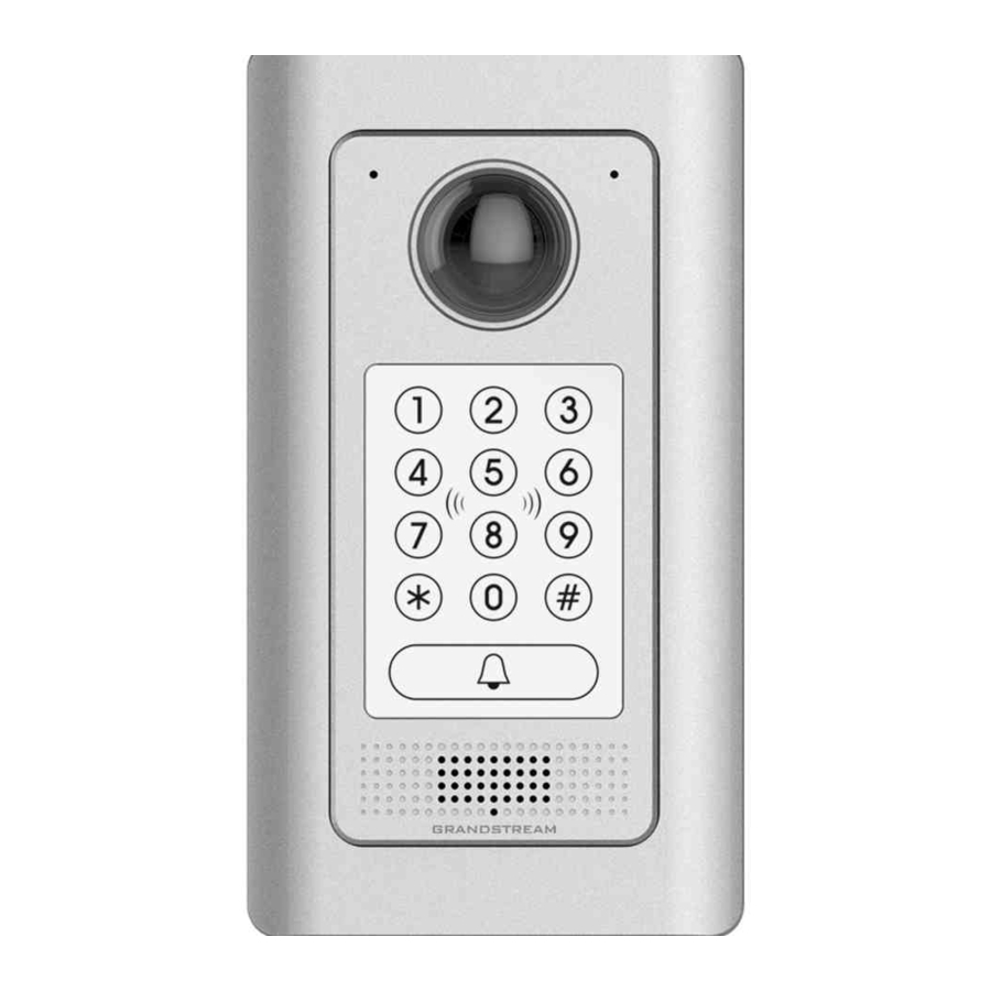
INTRODUCTION GDS3710 HD IP Video Door System is a hemispheric IP video door phone and a high-definition IP surveillance. GDS3710 is ideal for monitoring from wall to wall without blind spots. Powered by an advanced Image Sensor Processor (ISP) and state of the art image algorithms, it delivers exceptional performance in all lighting conditions. -
Page 5: Gds3710 Wiring Connection
GDS3710 WIRING CONNECTION The first step to setup the GDS3710 in an environment is to choose the powering method then and connect an RJ45 cable so it can interact with the network and start operating. Two ways are possible to power the... -
Page 6: Alarm In And Alarm Out Pins
GDS3710 trough (12V,GND). Alarm In and Alarm Out PINs The GDS3710 have two Alarm input entries and two alarm output entries and a ground entry as shown in the following figure. P a g e... -
Page 7: Figure 4: Back Cover 2
Figure 4: Back Cover 2 The following table summarize the GDS3710 entries and their purpose. Jack Signal Function Note Orange / White Orange Data Green / White Ethernet Green POE 802.3af Class 3, 12.95W Please short these two wires PoE_SP2... -
Page 8: Figure 5: Alarm Input Example
Alarm In and Alarm Out are just electronic lock, they are either open to block the current or open to let the current pass through, therefore a third party power supply is needed to power the device connected to the GDS3710 via Alarm In or Alarm Out. Alarm In Connection Example Connect Alarm (IN1+, IN1-) or (IN2+, IN2-) to appropriate wires in order to receive signal from the third party device as shown below. -
Page 9: Figure 6: Alarm Output Example
Figure 6: Alarm Output Example P a g e GDS3710 Input/output Connection Guide... -
Page 10: Detect And Access To The Gds3710
Please trust and install the file downloaded if prompted by the Antivirus or Security software. Connect the GDS3710 to network with DHCP Server (Recommended) The GDS3710 by default has the DHCP client enabled, it will automatically get IP address from the network running DHCP server... -
Page 11: Figure 8: Gds3710 Login Page
“LiveView” and click the stream number. 2. GDSManager Utility Tool User can know the IP address assigned to the GDS3710 from DHCP server log or using the Grandstream GDS Manager after installing this free utility tool provided by Grandstream. Below user can find instructions for using “GDS Manager”... -
Page 12: Apple Platform
Figure 9: GDSManager Search Double click the column of the detected GDS3710, the browser will automatically open and show the device’s web configuration page. The browser will ask for plug-in if not installed, please authorize the installation of the plug-in. -
Page 13: Connect To The Gds3710 Using Static Ip
Connect to the GDS3710 using Static IP If there’s no DHCP server in the network, or the GDS3710 does not get IP from DHCP server, user can connect the GDS3710 to a computer directly, using static IP to configure the GDS3710. -
Page 14: Figure 11: Static Ip On Windows
Access the Web Configuration Interface. IE will indicate that “This website wants to install the following add-on: GSViewerX.cab from Grandstream Networks Inc.”, allow the installation. Firefox and Internet Explorer users need to download the plug-in from the GDS3710 WebGUI and install it in order to see the video... -
Page 15: Alarm In/Out On The Gds3710
ALARM IN/OUT ON THE GDS3710 The below diagram illustrate an example of peripheral connections for the GDS3710. Figure 12: Peripheral Connections for GDS3710 P a g e GDS3710 Input/output Connection Guide... -
Page 16: Configure Alarm In/Out On Gds3710
Configure Alarm In/Out on GDS3710 In order to configure the Alarm In/Out on the GDS3710, access the webGUI, after detecting the GDS3710 IP address using one of the methods previously mentioned, and log in as admin (the default user/pass for admin log in is admin/admin). -
Page 17: Alarm Action
Users can copy the configuration to different date during the schedule programming. Alarm Action This page specifies the configuration of Profile used by the Alarm Actions. A Profile is required before the Alarm Action can take effect. P a g e GDS3710 Input/output Connection Guide... -
Page 18: Figure 15: Alarm Action
When checked, an email will be sent when the events is triggered to the pre-configured email account. Sound Alarm When selected alarm will be played from the GDS3710 Built-in Speaker. Alarm Output An alarm will be sent to the Alarm Output interface if this option is checked. -
Page 19: Alarm Phone List
Once the event is triggered (Motion Detection, Door Bell Pressed…) the GDS3710 will call the first number, once time out is reached and no answer is returned from the first number, the GDS3710 will try the next number on the list and so on. Once the remote phone answers the call an alarm will be played to notify users that an event is triggered. -
Page 20: Figure 18: Events Page
Figure 18: Events Page Alarm can be triggered either by motion detection or by GDS3710 input. Motion Detection Users can select a specific region to trigger the alarm using motion detection. P a g e GDS3710 Input/output Connection Guide... -
Page 21: Figure 19: Region Config
Select a zone on the screen then click on Clear to delete the region. Sensitivity Region sensitivity ( value between 0-100%). Select Alarm Schedule Select the Schedule programmed. Select Alarm Action Profile Select the programmed Alarm Action. Digit Input Figure 20: Digit Input P a g e GDS3710 Input/output Connection Guide... -
Page 22: Table 4: Digit Input
Hostage Mode: “* HostagePassword #”. Tamper alarm is anti-hack from Hardware level. When this option is checked, if the GDS3710 is removed from the installation board, it will generate the alarm actions configured. There is an embedded mechanism on the GDS3710 that allow it to sense when the it is removed.
Need help?
Do you have a question about the GDS3710 and is the answer not in the manual?
Questions and answers