
Summary of Contents for TVU networks MLink TE4100
- Page 1 TVU MLink Set Up and Operating Guide Models TE4100 and TE4200 Version 5.5 857 Maude Avenue, Mountain View, CA 94043 Telephone: (650) 969-6732 • FAX: (650) 969-6747 www.tvunetworks.com Printed in U.S.A. ©2016 TVU networks Corporation...
- Page 3 TVU MLink Set-up and Operating Guide Notices Copyright © 2016 TVU networks Corporation. All Rights Reserved. Photographs are the copyright of their respective owners. Contact TVU networks Corporation at our Web site: www.tvunetworks.com Trademark Notices TVU networks Corporation Trademark Information The following are trademarks of TVU networks Corporation and/or its affiliates in the United States and/or other countries: TVU®, TVU Networks® and TVUPack Other Trademark Information The following are trademarks of their respective owners or companies: TRADEMARK OR REGISTERED TRADEMARK COMPANY Verizon® Verizon Communications, Inc. AT&T® AT&T, Inc. Huawei® Huawei Technologies Co. Ltd. Velcro® Velcro Industries, B.V. FCC/CE Compliance Federal Communications Commission (FCC) Regulation of ENG Mobile Systems The FCC provides specific policies and procedures related to radio frequency (RF) emissions in mobile and portable devices. The FCC outlines test requirements and specific test procedures based on the type of device. These test requirements and procedures can also cover Specific Absorption Rates (SAR) for RF. The TVU MLink device has always conformed to all applicable FCC regulations covering mobile systems for electronic news gathering. All required tests for the TVU MLink device as outlined in the regulations were performed by a third party testing lab which issued a certificate of compliance for the TVU MLink. The certificate is applicable to both the FCC and CE. Additionally, the data modems used in TVU MLink are commercially available off-the-shelf brands and have been FCC and carrier certified. Supporting documentation demonstrating TVU MLink's compliance with the applicable FCC regulations is available upon request. Please contact us at +1.650.969.6732 for assistance and questions regarding approved modem cards for use with TVU MLink. TVU MLink Page 3 of 75...
-
Page 4: Table Of Contents
TVU MLink Set-up and Operating Guide INTRODUCTION ............................6 ABOUT THIS GUIDE ........................... 6 TVU MLINK SYSTEM OVERVIEW ......................6 TVU ML ........................6 RONT ACEPLATE TVU ML (A) .......................... 7 ANEL TVU ML (B) .......................... 7 ANEL TVU MLINK FRONT PANEL CONTROLS AND OPERATIONS ..............8 TVU MLink Controls .............................. - Page 5 ) ............................... 61 PTIONAL TVU MLINK TE4200 CONFIGURATIONS ....................63 TECHNICAL SPECS ..........................66 TVU MLink TE4100 & TE4200 ..........................66 TVU Modem Module ..............................66 Modem Module Mount Plate ............................. 66 External Antennas ..............................66 CONTACTING TVU NETWORKS ......................68 APPENDIX A: TVU RECEIVER TR3700 ....................
-
Page 6: Introduction
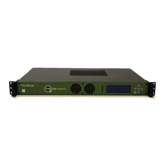
TVU MLink Set-up and Operating Guide NTRODUCTION The TVU MLink product series delivers a complete versatile cellular ENG solution for OB vehicles and fixed locations that is designed to automatically aggregate multiple cellular, microwave and satellite connections together simultaneously to ensure that field crews have the necessary bandwidth to broadcast live real-time video in challenging environments. The TVU MLink fixed transmitters feature a 1RU chassis that will be available in two different configurations. TVU MLink TE4200 transmitter can transmit live video over two Ethernet connections, WiFi and up to eight cellular modem cards simultaneously. This solution also includes multiple external antennas in removable or fixed roof mounted configurations designed to give ENG vehicles optimal resiliency. TVU MLink TE4100 features a single Ethernet port and VBR encoding, making it the ideal choice for fixed installations. BOUT UIDE This guide provides simple instructions for setting up and operating TVU MLink TE4200 and TVU MLink TE4100. TVU ML YSTEM VERVIEW TVU MLink Front Faceplate A B C D E F G Figure 1 Label TVU MLink Front Panel Power Button USB Port USB Port Vent; Do not block Vent; Do not block Status Display: Displays the paired receiver, the preset transmission mode, and the type of input. During bootup, the PID of the system is displayed. Control Buttons Table 1 TVU MLink Page 6 of 75... -
Page 7: Tvu Mlink Back Panel (A)
TVU MLink Set-up and Operating Guide TVU MLink Back Panel (A) For the TE4100, only the right Ethernet port is active. B C D E F G H I J K Figure 2A Label TVU MLink Back Panel Connections AC Power Vent; Do not block 2 GigE Ethernet Ports (Note: On the TE4100, only has the right Ethernet port active while both ports are active on the TE4200) Display Port: Connect the supplied Display Port to VGA adapter for primary status display purposes HDMI Display Port (Note: Also possible to view the primary status display via this port) USB Ports: The top left port supports Wi-Fi while the bottom right port supports Hotspot Modem Module Connector SDI Input HDMI Input Audio Output (IFB) Not used Table 2A TVU MLink Back Panel (B) For the TE4100, only the right Ethernet port is active. H I K L Figure 2B Label TVU MLink Back Panel Connections AC Power Vent; Do not block 2 GigE Ethernet Ports (Note: On the TE4100, only has the right Ethernet port active while both ports are active on the TE4200) TVU MLink Page 7 of 75... -
Page 8: Tvu Mlink Front Panel Controls And Operations
TVU MLink Set-up and Operating Guide Display Port: Connect the supplied Display Port to VGA adapter for primary status display purposes HDMI Display Port (Note: Also possible to view the primary status display via this port) USB Ports: The top left port supports Wi-Fi while the bottom right port supports Hotspot Modem Module Connector SDI Input Not Used Not Used Audio Output (IFB) Not Used HMDI Input Not Used Table 2B TVU ML RONT ANEL ONTROLS AND PERATIONS TVU MLink features front panel buttons that provide control of commonly used functions on the device including switching receivers, switching transmit modes, triggering Live, etc. TVU MLink Controls Figure 3 Label TVU MLink Button Controls Use left and right arrows to switch between paired receivers or transceivers Press to go live or to confirm an action Press to stop live transmission or deny an action Use up and down arrows to switch between preset transmission modes Table 3 TVU MLink Page 8 of 75... -
Page 9: Tvu Mlink Front Display Panel
TVU MLink Set-up and Operating Guide TVU MLink Front Display Panel Figure 4 Label TVU MLink Front Display Panel Transmission Status Monitor: Provides the current transmission status of the Pack. If the indicator is blinking “LIVE”, then the transmission is live. If the indicator displays “STDBY”, a camera source or input is connected f a to the unit and ready to transmit live. I camera or input source is not connected, it will say “Online”. The receiver’s name with which the MLink unit is paired Receiver Name: Preset Transmission Mode: The default present transmission mode for the selected receiver will be displayed under the receiver’s name. Input Source Table 4 Powering on/off the TVU MLink To turn on TVU MLink, simply press the power button on the front left side of the unit (Figure 1, A). While turning on, the name and PID number of the unit will be displayed on the screen. To turn off the TVU MLink, hold down the power button for four seconds. If the power button is not held down for four seconds, the unit will simply restart. Choosing a Receiver or Transceiver The receiver’s name with which the MLink unit is paired will be displayed in the center of the screen on the unit (Figure 4, B). If the MLink unit is paired with multiple receivers or transceivers, you can choose a different receiver by using the right and left arrow keys. Note: The default preset transmission mode may be different for each receiver or transceiver. Thus, you may see the preset transmission mode change when switching between different receivers and transceivers. Choosing a Preset Transmission Mode The preset transmission modes are displayed under the receiver name (Figure 4, C). If you would like to choose one of the other preset transmission modes, use the up down arrow keys to scroll through the options. TVU MLink Page 9 of 75... -
Page 10: Going Live
TVU MLink Set-up and Operating Guide Going Live Make sure that a camera or input source is connected to the MLink. If a camera or input source is not connected, it will say “Online” in the top left corner of the status display screen. If a camera source is connected, the unit will say “STDBY” in the top left corner (Figure 4, A). To go live, first press the green check mark button. The unit will then ask if you would like to start a live transmission (Figure 5). To confirm, click the green check mark again. To deny, click the red X. The selected preset transmission mode and paired receiver name will be displayed as well. Figure 5 While live, the unit will blink “LIVE” in the top left corner of the status screen (Figure 6). The variable bitrate will also be displayed in real time next to the flashing “LIVE” icon. The selected preset transmission mode, paired receiver name, and input source will also be displayed. Figure 6 To stop a live transmission, hit the red X. The unit will then ask if you would like to stop the live transmission (Figure 7). To confirm, click the green check mark. To deny, click the red X again. Once the live transmission has stopped, the screen will return to “STNDBY” mode (Figure 4). Figure 7 TVU MLink Page 10 of 75... -
Page 11: The Tvu Mlink Transmitter Status Monitoring And Control From The Web
TVU MLink Set-up and Operating Guide TVU ML RANSMITTER TATUS ONITORING AND ONTROL FROM THE From a web browser, a TVU Transmitter status can be monitored and various parts of the transmission can be controlled. This interface can be accessed using a standard web browser connected to the TVU MLink’s Hotspot. See Configuring the TVU MLink for Hotspot (p. 27) for details on how to connect to the Hotspot. Note: The images below are examples of how the screen would appear on an iPhone web browser TVU Transmitter Status Screen The Status tab provides system information. TVU MLink Page 11 of 75... - Page 12 TVU MLink Set-up and Operating Guide Figure 8 TVU MLink Status Screen Label TVU Transmitter Status Screen Description Scroll bar that allows users to monitor and control all aspects of a transmission including datacards, Ethernet, Wi-Fi, BGAN, Receiver, and return video feed. Information regarding a particular TVUPack such as model number, version number, and PID. CPU: Current CPU capacity and temperature Battery: Main battery status Input: Input source IFB Audio Level: Change the audio level of the IFB function Video: Transmission information and status Network: Modem card information including type, connectivity, and IP address all organized by slot number Table 5 TVU MLink Page 12 of 75...
-
Page 13: Ethernet
TVU MLink Set-up and Operating Guide Ethernet The Ethernet screen provides configuration and set-up information. D F G Figure 9 Label TVU Transmitter Ethernet Status Screen Description Interface: Select either Ethernet or USB from drop-down menu IP Method: Select either Static or DHCP MAC Address: Media access control address IP Address: Entered manually if in Static mode; automatically generated if in DHCP mode Mask: Entered manually if in Static mode; automatically generated if in DHCP mode Gateway: Entered manually if in Static mode; automatically generated if in DHCP mode Keep Static IP: When “Static” is selected from the “IP Method” drop down menu, the check box can be ticked to keep the desired static IP address. Apply: Press Apply for the changes to take effect Table 6 TVU MLink Page 13 of 75... -
Page 14: Wifi
TVU MLink Set-up and Operating Guide WiFi The WiFi screen provides configuration information and access to change the WiFi settings. Any modem can be replaced with a WiFi adapter in the TVU transmitter and the TVU Transmitter can support multiple WiFi connections. Each port in the modem module can connect to a USB WiFi modem or a WiFi adapter. When multiple WiFi adapters are connected in the modem module, the WiFi tab on the web interface will allow the user to scan slots for available WiFi adapters and configure the WiFi login information. Figure 10 Label TVU Transmitter Wi-Fi Status Screen Description Scan: Scan for available networks and will display the list of available networks to select from the center box. Security Type: Drop down menu displays the security type of the connection SSID: Wireless network name Apply: Press Apply for the changes to take effect Select the slot with which a modem was replaced with a WiFi adapter. Table 7 TVU MLink Page 14 of 75... -
Page 15: Hotspot
TVU MLink Set-up and Operating Guide Hotspot The Hotspot tab provides status information on clients connected via the Hotspot. The Hotspot card should always be placed in the USB port on the TVU Transmitter. Figure 11 Label TVU Transmitter Hotspot Status Screen Description Connected Client Lists: Displays list of devices connected via Hotspots SSID: Allows you to customize the Hotspot SSID Password: Allows you to customize Hotspot password (Note: the new password must be 8 characters and does not take affect until the system is rebooted). Route: Choose a specific modem, WiFi network, or Ethernet connection, or choose Auto for the Hotspot to be routed through a random modem connection. Band: Option to choose 2.4GHz or 5GHz Apply: Press Apply for the changes to take effect Table 8 Modem The Modem screen provides modem configuration information. Many cellular data cards are automatically detected by the TVU transmitter and will self-configure. If this is the case, no further action will be required. If a data card needs to be configured, you can use this tab to configure specific data cards. TVU MLink Page 15 of 75... - Page 16 TVU MLink Set-up and Operating Guide Figure 12 Label TVU Transmitter Modem Status Screen Description Scan: Search for available modems Available Slots: Drop-down list of slots that are available for configuration ESN/IEMI: A modem’s unique identification number Username: Obtain carrier user name information from the network carrier Password: Obtain carrier password information from the network carrier Encryption: Select the appropriate encryption standard from the drop-down menu Dial number: Obtain carrier dial information from the network carrier APN: Obtain APN information from the network carrier Carrier: When roaming, this drop down menu allows users to select the desired carrier Scan Carrier: Scan for the carrier selected from the drop down menu Apply: Press to apply desired changes Table 9 TVU MLink Page 16 of 75...
-
Page 17: Upload
TVU MLink Set-up and Operating Guide Upload The Upload screen gives you the ability to assign uploaded files to a particular receiver. Figure 13 For each file uploaded, choose the specific receiver to which you would like the files to be uploaded from the drop down menu under to the file name (A) (Figure 13). Once the receiver is chosen, you can choose to make it the default receiver so that all future files are uploaded to that specific receiver (B). Then hit apply (C). For instructions on uploading files from a TVU Transmitter to the TVU Receiver, see AutoSync File Transfer Using Wireless Hotspot, or Automatic Ingest of USB Memory Stick Content to TVUPack (p.49) TVU MLink Page 17 of 75... -
Page 18: Bgan
TVU MLink Set-up and Operating Guide BGAN The BGAN tab provides BGAN transmission information. Figure 14 Label TVU BGAN Status Screen Description Device Name: Displays the device name Signal: Displays the signal strength Linked: Indicates if the BGAN is connected Link Type: Indicates the BGAN link type Drop down menu that allows for the selection of a specific streaming class Table 10 BGAN Configuration The TVUPack TM8200 can support BGAN Hughes 9201 for automatic data connections. Follow these steps to set up the auto connection: 1. Set up the BGAN device to Auto Register Network mode by LaunchPad. A. To enable automatic registration, Select Terminal > AutoStart mode. The Configure Auto-Start screen is displayed: TVU MLink Page 18 of 75... - Page 19 TVU MLink Set-up and Operating Guide Figure 15 B. Check Automatically register with the network after BGAN terminal switches on and then click OK. Then power off the BGAN device. 2. Connect the BGAN to the TM8200 by Ethernet cable. 3. Pointing to satellite by the Web UI of the Pack configuration from iPad or IE, for Hughes 9201, it has signal strength indicators on the panel. Note: You may need to manually adjust the equipment location and orientation in order to confirm the signal strength is greater than 60% 4. Set the link mode. “X-stream” is the default mode set up by the TVUPack automatically. Figure 16 TVU MLink Page 19 of 75...
- Page 20 TVU MLink Set-up and Operating Guide Note: If the interface connected with the BGAN device is consistently yellow and does not change to green after setting up the “Link Type”, please check whether the BGAN equipment - when connected to a PC - can work normally with LaunchPad’s X-stream mode. 5. Check on the TVUPack’s screen to make sure the BGAN is connected. 6. Power off the BGAN device to close the connections. If the BGAN is the only device connected with the Receiver, then the Receiver will automatically change the bitrate to 80% of the XStream with four seconds of delay at the CBR mode. If there is no BGAN connected, the menu will display “No Device Detected” (Figure 17) Figure 17 Note: If you require additional assistance, please contact TVU Networks Customer Support at +1 650 440 4812. TVU MLink Page 20 of 75...
-
Page 21: Receiver Status
TVU MLink Set-up and Operating Guide Receiver Status This screen displays Line Quality and Error Rate information. Touch the Start/Stop Live button to control the live transmission. You use this screen to control Bit Rate and Delay by entering your data in the respective boxes and touching the Apply button to set them. This screen also allows you to choose the operational mode provided in the drop down menu at the bottom of the screen: Interview, Normal, Fast Moving, SD, Tape Feed and User Definable. Figure 18 R Status screen Label Record Mode: Controls and Functions Description R: Displays receiver name. To view a different available receiver, click the drop down menu to scroll through the options. Solo: When checked, the particular TVUPack will only be shown as “online” on the receiver selected from the drop down menu. Bitrate/Delay: Enter the desired transmission Bitrate and delay(s). Live/Stop Live: Starts and stops the live transmission. Apply: Applies changes made to bitrate, latency, or mode. Displays current TVUPack Receiver ID, TVUPack Transmitter ID, Line Quality, Error Rate and Auto Set. Mode: Select an optimized preset bit-rate and latency based on broadcast setting(s) by choosing a different mode. Table 11 TVU MLink Page 21 of 75... -
Page 22: Return Video Feed
TVU MLink Set-up and Operating Guide Return Video Feed This is a feature that can only be used on a TX3200, TX3000 or GX3200 series Transceiver. It will allow the camera operator in the field to have the ability to watch a return video feed from the studio of their Pack transmission or from an SDI input on the Transceiver. The return video feed can be sent from the Receiver to the Transmitter when in Live, Online or Standby modes. View the return video feed via the TVU Transmitter Hot Spot using any WiFi enabled iOS device with a standard Safari web browser. See Configuring the TVU Transmitter for HotSpot (p. 27) for details on how to connect to a Hot Spot. The latency of the return feed or SDI feed is about 3 seconds (under normal conditions) Resolution is 320x240 and includes 2-ch. of audio. The return feed / SDI feed is not intended as cue channel, but rather provides those in the field with a confidence monitor or the ability to monitor another source. The user is able to select which Transceiver the Return Video Feed comes from. Use the drop down menu (A) to select the desired Transceiver (Figure 19). Figure 19 Label TVU Video Feedback Status Screen Description Displays available transmitters that can be streamed for video return purposes. Pack: Provides a low-res return feed of your Pack transmission for monitoring purposes. Latency of the return feed is less than 3 seconds under normal conditions. You must select the receiver that is currently streaming your Pack from the drop down menu in order to see the feed. You cannot view other Pack feeds. SDI: Provides a low-res return feed of the SDI input at the Transceiver for monitoring purposes. Latency of the return feed is less than 3 seconds under normal conditions. Table 12 TVU MLink Page 22 of 75... -
Page 23: Ip Source
TVU MLink Set-up and Operating Guide IP Source The IP Source tab allows the user to select the source with which to go live. Either select the camera source or select an outside IP source. Figure 20 Figure 21 Label TVU IP Source Screen Description SDI: This is the camera source connected to the TVUPack IP Source: Allows users to add an IP source with which to go live Home: Send all IP sources in one matrix picture to TVU receiver Type in the valid IP address of the source with which you want to go live Apply: Adds the new IP Source Table 13 Microwave The Microwave tab provides information and control of the microwave transmission. This is applicable when using a TVUPack powered by Vislink Hybrid Technology and Silvus MIMO Microwave Mesh technology. This tab allows the user to select one of ten presets channels (Figure 22). TVU MLink Page 23 of 75... - Page 24 TVU MLink Set-up and Operating Guide Preset Frequency (MHz) Modulation Guard FEC Ch1 2031.500 QPSK 1/8 1/2 Ch2 2043.500 QPSK 1/8 ½ Ch3 2052.500 QPSK 1/8 ½ Ch4 2067.500 QPSK 1/8 ½ Ch5 2079.500 QPSK 1/8 ½ Ch6 2088.500 QPSK 1/8 ½ Ch7 2103.500 QPSK 1/8 ½ Ch8 2458.500 QPSK...
- Page 25 TVU MLink Set-up and Operating Guide Figure 23 Label TVUPack Microwave Status Screen Description This section provides information regarding the current microwave transmission such as the channel, channel frequency, mode, guard and FEC. Load Preset: Load a preset Microwave channel. There are 10 default setting pre- loaded by Vislink. These preset channels are channels 1- 10. Apply: Applies the selected “Loaded Preset” channel to the current settings for the microwave transmission. The “Custom” section allows users to create a custom channel for a live transmission. Channel 11 – 16 are customizable. Load Preset: Drop down menu that allows you to select the channel that you would like to customize Ch. Freq.: Set the desired frequency of the custom channel DVB-T COFDM: Select the desired DVB-T COPDM for the custom channel Modulation: Select the desired modulation for the custom channel Guard: Select the desired gaurd for the custom channel FEC: Select the desired FEC for the custom channel Power: Select the desired power level for the custom channel. Note: It is advised to TVU MLink Page 25 of 75...
-
Page 26: Recording
TVU MLink Set-up and Operating Guide Label TVUPack Microwave Status Screen Description keep the power level on “Low”. There are greater concerns regarding safety when the transmission is on a higher power level. Add: Add the customized channel Table 14 Recording The Recording tab allows users to isolate a specific segment of video with the touch of a button. Note: The TVU device is always recording when it is powered on and a valid video source is connected. Figure 24 Label TVUPack Recording Status Screen Description Mark In: Marks the IN point of a segment in the recorded video on the TVUPack Mark Out: Marks the OUT point of the segment in recorded video on the TVUPack. TVU MLink Page 26 of 75... -
Page 27: Configuring The Tvu Transmitter For Hotspot (Optional)
TVU MLink Set-up and Operating Guide Label TVUPack Recording Status Screen Description Note: Once an IN and OUT point are identified, it is possible to play the clip, copy the clip locally to an inserted USB thumb drive, or upload it directly to the selected Receiver. Name: Designate a specific name for the recorded segment Apply: Add the recording to the list below This allows you to search for recordings by date. Simply click on the calendar and select the day of the recording you would like to bring up in the list below. Query: Searches recordings completed on the selected day Select All: Select all of the recordings in the list below This section displays all the recordings completed on the selected day as well as the size of the file. To select a specific video file, simply click on the check box next the video name. Play: Provides for a video preview of the selected clip Copy: Copies the selected clip to a USB stick. USB stick must be plugged into the TVUPack in order for the file to be transferred. Upload: The selected clip will be uploaded to the default receiver designated in the “Receiver” tab. Table 15 Configuring the TVU Transmitter for Hotspot (Optional) You can use an iPod or smart mobile device for wireless monitoring and control of the TVU transmitter. To do this, you must first join the MLink’s internal hotspot. 1. Make sure the optional hotspot card is in the bottom left USB port on the back of the MLink unit. 2. Search for the hotspot on your iPod/smart device. The SSID will be TVUPACK_XXXX where X is the last 4 digits of the MLink’s PID. 3. Connect to the SSID using your iPod/smart device. 4. The default password is the last 8 digits of the PID of the MLink (Note: All characters are uppercase). Note: The password can be changed in WebUI is desired. Once the connection is established, open a web browser and go to http://192.168.3.1 to see pack status. TVU MLink Page 27 of 75... -
Page 28: Display Status Screen Via Display Port Or Hdmi Port
TVU MLink Set-up and Operating Guide Display Status Screen via Display Port or HDMI Port A monitor can be connected to the display port or HDMI port on the TVU MLink in order to see a more detailed status display screen. When a camera is attached to the TVU MLink unit and both are powered on, the following Video Preview and Transmission Status Screen will appear in the screen: Figure 25 Live Status Screen Label TVU Transmitter Live Status Screen Description Input Preview: Shows the live picture from the camera and captured in TVU MLink. Transmission Status Monitor: Provides the current transmission status of the Pack. If the indicator is red, TVU MLink is transmitting a “Live” picture. If the indicator is black/gray, TVU MLink is not transmitting live and is on “Standby”. File Upload Status Monitor: Displays the progress of any file being uploaded from the TVU MLink’s SSD hard drive to the TVU Receiver. Please note that uploading a file is not possible when the Pack is in “Live” mode. IFB Indicator: Indicates whether or not the IFB function is on. The small red IFB box indicates that the IFB function is on and connected. If no red box appears, IFB is not connected or is off. TVU MLink Page 28 of 75... -
Page 29: Standby Video Input Status Via Display Port Or Hdmi Port
TVU MLink Set-up and Operating Guide Label TVU Transmitter Live Status Screen Description System Status Monitor: Displays the current system status for TVU MLink including the Bit Rate (B/R), the current Latency transmission setting, the TVU Receiver the Pack is currently transmitting to, the current type of pre-set transmission Setting, the Video Input source, the Video Format. Note: System Status values will only appear when the Transmission is Live. Data Card Status Monitor: Shows the current number and status of all data cards connected to the TVU MLink. The status of data cards connected to the Pack will appear as green, red or black. Green status indicates that the data card is connected. Red status indicates that the data card is attempting to dial. Black status indicates there is no card. TVU MLink PID and Firmware Version Information: Indicates the unit’s identifying PID and version number and used when contacting TVU customer support. Battery Status: Indicates the status of battery levels for installed batteries. Audio Input Level Monitor: Dynamically displays the audio input level (DBFS) for TVU MLink with graphical colors. Table 16 Standby Video Input Status via Display Port or HDMI Port When no camera is connected to the TVU MLink unit, the following is displayed on a monitor when connected to the TVU MLink unit via the display port or HDMI port: Figure 26 Label TVU Transmitter Standby Video Input Status Screen Description Connection Status: Shows the status and IP of each network connection. The status of data cards connected to the Pack will appear as green, red or black. Green status TVU MLink Page 29 of 75... -
Page 30: Tvu Transceiver Tx3200 Features And Indicators
TVU MLink Set-up and Operating Guide indicates that the data card is connected. Red status indicates that the data card is attempting to dial. Black status indicates there is no card Transmission Status Monitor: Provides the current transmission status of the Pack. If the indicator is red, TVU MLink is transmitting a “Live” picture. If the indicator is black/gray, TVU MLink is not transmitting live and is on “Standby”. If the status says “Online,” the camera source is not connected. File Upload Status Monitor: Displays the progress of any file being uploaded from the TVU MLink SSD hard drive to the TVU Receiver. Please note that uploading a file is not possible when the Pack is in “Live” mode. Data Card Status Monitor: Shows the current number and status of all data cards connected to the TVU MLink. The status of data cards connected to the Pack will appear as green, red or black. Green status indicates that the data card is connected. Red status indicates that the data card is attempting to dial. Black status indicates there is no card. TVU MLink PID and Firmware Version Information: Indicates the unit’s identifying PID and version number and used when contacting TVU customer support. Battery Status: Indicates the status of battery levels for installed batteries. Audio Input Level Monitor: Dynamically displays the audio input level (DBFS) for TVU MLink with graphical colors. Table 17 TVU T TX3200 F RANSCEIVER EATURES AND NDICATORS TVU Transceiver TX3200 Front Panel with Faceplate Figure 27 Label TVU Transceiver Front Panel Faceplate Power Button USB Ports Table 18 TVU MLink Page 30 of 75... -
Page 31: Tvu Transceiver Tx3200 Back Panel Connections (Standard Sdi Version)
TVU MLink Set-up and Operating Guide TVU Transceiver TX3200 Back Panel Connections (Standard SDI version) Figure 28 Label TVU Transceiver Back Panel Connections (SDI) Vent; Do not block AC Power 1 GigE Ethernet Port Display Port: Connect the supplied Display Port to VGA adapter for primary display purposes (see image below) HDMI Display Port USB Ports SDI Output SDI Input Audio Output Not Used Reference input: Allows for time sync with the television station’s broadcasting system Table 19 VGA Adapter TVU MLink Page 31 of 75... -
Page 32: Tvu Receiver: Network And Firewall Configuration
TVU MLink Set-up and Operating Guide TVU Receiver: Network and Firewall Configuration TVU Networks recommends assigning a static IP address to the TVUPack receiver to ensure the network configuration remains stable. All the incoming ports referred to in this section are configurable. Please contact TVU Networks Customer Support if you wish to use a configuration other than the one specified in this documentation. Please configure your firewall or router as follows: 1. Allow TCP outgoing from the TVU receiver on port 3970. 2. Allow UDP/TCP outgoing from the TVU receiver on port 123. 3. Permit all TCP/UDP incoming traffic for port 8088 to receiver. 4. Forward all traffic arriving on port 8088 of the external firewall interface to the IP address of the TVU Receiver. This setup allows the TVUPack and receiver to automatically link with each other and permit video transport. Recommended firewall configuration for TeamViewer TVU Networks uses TeamViewer software to enable remote support and troubleshooting. To enable this software, please ensure that either port 80(TCP) or port 5938(TCP) are open for outbound connections. Recommended firewall configuration for remote control of TVUPack receiver from iPod or smartphone The TVUPack hotspot feature allows remote configuration of the TVUPack receiver settings from a smartphone. To enable this feature, permit all TCP/UDP incoming traffic for port 8288 to receiving terminal; forward all traffic arriving on port 8288 of the external firewall interface to the IP address of the TVU Receiver. This port is configurable. Recommended firewall configuration for the FTP server This feature allows files to be uploaded to the FTP server in the Receiver. To enable this feature, permit all TCP/UDP incoming traffic for port 21 to the receiving terminal; forward all traffic arriving on port 21 of the external firewall interface to the IP address of the TVU Receiver. This port is configurable. Recommended firewall configuration for remote configuration of a TVUPack from the receiver A TVUPack and its modems can now be configured from a remote location. To enable this feature, permit all TCP/UDP incoming traffic for port 22 to the receiving terminal; forward all traffic arriving on port 22 of the external firewall interface to the IP address of the TVU Receiver. This port is configurable. TVU MLink Page 32 of 75... -
Page 33: Bandwidth Recommendations
TVU MLink Set-up and Operating Guide Recommended firewall configuration for the Return Video Feed This is a feature that can only be used on a TX3200 or GX3200 series Transceiver. It will allow camera operator in the field have the ability to watch a return video feed from the studio of their Pack transmission or from an SDI input at the Transceiver. To enable this feature, please ensure that you permit all TCP/UDP incoming traffic for port 8488. This port is configurable. In order to view a TVUPack feed remotely, ensure that port 10003 is open for all inbound traffic. To view an SDI feed remotely, make sure that port 10004 is open for all inbound traffic. Note: these are default ports, configurable if required. For more details, please contact TVU support by phone at +1.650.440.4812, by email at support@tvupack.com, or by skype at skype.tvupack. Bandwidth Recommendations Allowances should be made for bandwidth of incoming TVUPack transmissions based upon the following criteria: Each TVU receiver can utilize up to 20mbps of downstream bandwidth per live Pack feed. A minimum of 2mbps upstream bandwidth per Receiver is required for all features to function efficiently. We recommend a stable, low latency connection with guaranteed bandwidth for best results. TVU MLink Page 33 of 75... -
Page 34: Operating Tvu Transceivers & Receivers
TVU MLink Set-up and Operating Guide TVU T & R PERATING RANSCEIVERS ECEIVERS TVU Transceivers and Receivers have two operating modes: Live and Record. You can pair multiple TVU transmitters to a Transceiver or Receiver, but can only receive video from one at a time. Depending on your specific license configuration, any number of TVU transmitters can be paired with your Receiver. For owners of the TVUPack HD version, please contact TVU Customer Support at +1.650.440.4812 for instructions on setting up the pack for HD mode. Live Viewing Mode Figure 29 Live Viewing Mode Screen Live Mode: Controls and Functions Label Live Mode: Controls and Functions Description System Information: Displays Receiver Name, PID (unique identifier for TVU Receiver), Build Version, Build Date and Record Time Remaining (if the optional Receiver record option is select). Quality Histogram and Post-Live Quality Histogram: Shows the total transmission encoding bit-rate over a period of time as well as gives users access to a post-live quality histogram. See Figure 30 and 31 Status panel: Displays error rate, line quality, and battery status. See Figure 30 Transceiver Information: Displays the input type and format, the output type and format, IFB status and IFB signal. See Figure 30 TVU MLink Page 34 of 75... - Page 35 TVU MLink Set-up and Operating Guide Label Live Mode: Controls and Functions Description Refresh button: Resets the video stream. See Figure 30 Stop buttons (x2): Clicking on either Stop button ends the live transmission. Audio level light display: The two light displays provide visual monitoring of your audio levels. This displays dBFS audio input level at the Receiver. See Figure 30 Mode selection button and mode indicator lights: Use this button to toggle through the receiver operational modes. See Mode Selection (page 11) for more information Operational mode selection buttons: Use the operational mode buttons to choose an appropriate capture quality. Each mode has a default bit rate and delay. See Figure 32 Bitrate and delay controls: Sliding bars allow you to manually set the target bit rate and delay levels. See Figure 32 Datacard monitor panel: This monitor panel displays the current status of each data card. See Figure 33 Monitor Histogram: Displays throughput and IP address on each modem (mb/s). By right clicking on the histogram scale, you can configure the datacards of a particular transmitter. See “Configuring Modem Cards from the Receiver Interface” on page 41. Connection mode and Connection strength indication: The connection mode is displayed when available in the dark gray box between the carrier name as well as the connection strength. See Connection Mode and Connection Strength (page 39) for more information Reset: Provides a full power reset for a particular modem (TM8200 only). Use this feature when the modem is no longer able to connect or is having problems. On the TM8100, pressing “RESET” will force the modem to reconnect. See F on Figure 33 Scale: This drop down menu allows you to set the scale for the histogram graph. Once the scale has been changed, it will affect all of the histogram graphs displayed. Available selections are 1.2Mb/s, 2.4 Mb/s, 6Mb/s, and 12 Mb/s. Thumbnail of current video feed from TVUPack: The left-hand column of the TVUPack monitor features an icon of the current feed. If a transmitter is live, a red box will appear around the thumbnail image. GPS information: If a TVUPack transmitter is used with modems that support GPS, a display of the transmitter’s location can be retrieved. See GPS Locator (page 39) for more information IFB Indicator: The IFB indicator is displayed below the transmitter’s thumbnail picture. See Figure 36 Stop buttons (x2): Clicking on either Stop button stops the live transmission. Dynamic Sorting: Sort all of the TVU transmitters alphabetically or based on their live status. See Figure 37 Table 20 TVU MLink Page 35 of 75...
- Page 36 TVU MLink Set-up and Operating Guide Status Panel Arranged vertically on the right hand side of the receiver panel are a number of indicators designed to help an operator make quality and troubleshooting decisions. Information such as error rate and line quality is displayed as well as a quality histogram that depicts the total transmission encoding bit-rate over a period of time (A) (Figure 30). The histogram’s scale can be change by selecting a different display option on the drop down menu (B). The status of the transmitter’s batteries (TM8200 only) (C) is also displayed. See troubleshooting section for more information on interpreting these numbers. Transceiver Information Displays input type and input format of the transmitter, which are displayed as T Input and T Format respectively (D) (Figure 30). The output type and output format of the transmitter are shown as R Output and R Format. Lastly, the IFB status and the IFB Signal are displayed (E). The IFB signal has a strength meter that depicts the input level of the IFB. To stop the live transmission, users can press the “Stop” button on the status panel (G). Figure 30 Refresh Button If the video goes black or pixelates heavily and does not recover automatically within 15 seconds, click the Refresh button (F) to reset the video stream and reestablish the connection (Figure 30). Post-Live Histogram The Quality button (H) allows users to access the post-live histogram (Figure 30). The post TVU MLink Page 36 of 75...
- Page 37 TVU MLink Set-up and Operating Guide live histogram allows users to recall a histogram of the entire past transmission and display it as a Web-based graph to review the overall performance (A) of that transmission over a certain period of time (B)(Figure 31). When the Quality button is selected, users will be directed to a webpage where they can access the post-live histogram. Users can look at a transmission that took place on a specific date as well as monitor the entirety of a live transmission (C)(Figure 31). The automatic refresh time can be set to a desired length (D) and users can search for a specific transmitter by typing in the PID number of the transmitter (E). Figure 31 Mode Selection The currently selected mode displays as a green-lighted tab. The modes that can be chosen are: • Live: Live mode is the primary interface to be used during a Live transmission. When this tab is selected, the status of each of the datacard network connections is displayed under the “Monitor” section of the interface and the Bitrate, Delay, and Operational Mode buttons are displayed. • Record: Record mode displays the store and forward interface for the preview, download, and management of Pack stored footage and files transferred via Auto Sync. Files transferred via FTP can also be accessed via this interface. Operational Mode Selection Depending on your news gathering environment, you can choose from the following preset bitrates and latencies (Figure 32): • Interview: Bitrate 2048, delay 2 seconds. • Normal: Bitrate 5120 delay 4 seconds. TVU MLink Page 37 of 75...
- Page 38 TVU MLink Set-up and Operating Guide • Fast Moving: Bitrate 5120, delay 8 seconds. • SD: Bitrate 2048, delay 4 seconds. • Tapefeed: Bitrate 10240, delay 10 seconds. This mode is optimized for content with multiple scene changes. • User 1 & User 2: These are user-definable presets. To program these, users simply right click the preset they would like to define. Users can then name the preset (C), manually set latency (D), or check “Set Current”, which will save the current latency setting to that particular preset (E). Press “Apply” to program once finished (F). Figure 32 Bitrate and Delay Controls The TVU Receiver has a Smart VBR scaling system. This means that the unit will automatically adjust the bitrate in order to output the best quality picture based on the desire latency. In order to effectively take advantage of the smart VBR scaling system, set the your desired latency (A) and then set the maximum bitrate you would like to utilize (B)(Figure 32). When in “Live” mode, the error rate and picture quality will automatically be adjusted based on the desired latency and the available bandwidth in order to produce the highest quality picture. Datacard Monitor Panel The check boxes associated with each cards’ status bar enables or disables a particular datacard (A)(Figure 33). If unchecked, it will not be used to pass data. If checked on (default), it will be used. Individual read out panels show the carrier name (when available) of each active card (B). The slot number of each datacard is indicated in front of the carrier name (C). To retrieve the IP Address of a particular datacard, mouse over the name of that datacard. If no name is automatically provided and is displayed as <name>, you can input your own name. However, this will reset upon reboot. The color indicators displayed within the carrier name panel indicates the following status: TVU MLink Page 38 of 75...
- Page 39 TVU MLink Set-up and Operating Guide • Red: Not connected • Green: Connected • Yellow: Dialing/Connecting • Gray: Disconnected or unplugged Figure 33 D E F Connection Mode and Connection Strength Indicator The connection mode (D) is next to the connection strength, which is indicated with three status bars (E)(Figure 33). If the bars are all gray, there is no connection. Three green bars indicate excellent connection strength. GPS Locator and Tracking When the transmitter is online, its name will be underlined underneath its thumbnail image. By clicking on the underlined name of the transmitter, the GPS data for that individual transmitter will appear. To locate all online transmitters at once, click “Locate All” at the top of the thumbnail column. Figure 34 TVU MLink Page 39 of 75...
- Page 40 TVU MLink Set-up and Operating Guide The location pin will show the name of the TVUPack and the accuracy of the location. Additionally, a tracked of the path of the transmitter will be displayed to easily identify recorded content based on location. Simply mouse over a section of the tracked path and a thumbnail image of the recorded content at that location will appear. In order to improve the location accuracy, make sure the TVUPack is connected to a WiFi card. Note: If there is no real-time GPS data for a particular TVUPack, cache GPS data will be used for that Pack and the location pin will be yellow. Figure 35 IFB Indicator IFB Indicator The five-color indicators are as follows (Figure 36): • Red: IFB function is in use Red-Gray: Either the transmitter has gone offline and the IFB will recover when it • is back online or the transmitter goes live with a different receiver while you were speaking with the Pack via the IFB function • Green: IFB function is connected but not in use • Green-Gray: Either when the transmitter is live with another receiver or when the transmitter is using the IFB function to speak with another receiver • Gray: IFB Function not available for this transmitter Figure 36 TVU MLink Page 40 of 75...
-
Page 41: Configuring Modem Cards From The Receiver Interface
TVU MLink Set-up and Operating Guide To use the IFB function, click the IFB indicator so that it turns red. The IFB on/off status is also indicated in the “Status” panel on the left side of the interface. Additionally, if a particular TVUPack has an IFB function, the IFB is automatically turned on when that transmitter goes live. Once the live transmission is stopped, the IFB function will be turned off. Dynamic Sorting To sort all of the TVU Transmitters alphabetically (B) or dynamically based on their live status (C), simply click the sort button (A) above the thumbnail images of the transmitters on the left side of the Receiver interface and choose the desired sorting method (Figure 37). Figure 37 Configuring Modem Cards from the Receiver Interface The modems can be configured on the TVUPack Receiver Interface by taking the following steps: 1) Right click the histogram of the modem you would like to configure Figure 38 2) A pop-up window will appear with the dial number, APN, and other necessary information TVU MLink Page 41 of 75... -
Page 42: Manual Selection Of Modem Carrier When Roaming
TVU MLink Set-up and Operating Guide Figure 39 3) Hit “Apply” and the modem will be configured Manual Selection of Modem Carrier When Roaming This function allows users to manually select which carrier a particular modem will roam on. When roaming, simply go to the web-based interface for monitoring and controlling the transmitter and select the “Modems” table. To access the web-based monitoring and control interface, right click the histogram of the modem you would like to configure (Figure 10). See Configuring Modem Cards from the Receiver Interface on pg. 41 for more information. Simply select the desired carrier from the drop down menu of available carriers (A). Then click “Scan Carrier” (B)(Figure 40). The roaming modem will automatically generate all of the necessary information for that carrier. TVU MLink Page 42 of 75... -
Page 43: Adding An External Ip Source
TVU MLink Set-up and Operating Guide Figure 40 Adding an External IP Source On the left side of the Receiver interface, there is a section for external sources such as YouTube (A)(Figure 41). In order to add an external source to the Receiver GUI, click the “+” on the section header (B). Figure 41 A pop-up screen will appear that will let you add an external source. Select the type of external source being added (A), insert the URL of the source and validate it (B), and name the source so that is easily recognized on the Receiver GUI (C)(Figure 42). Finally, click “Add”. A thumbnail icon of the added source will appear under the “External” section. TVU MLink Page 43 of 75... -
Page 44: Ip Streaming Output (Optional)
TVU MLink Set-up and Operating Guide Figure 42 Note: The information of the external source can be edited by clicking on the round tool icon in the bottom left corner of the thumbnail image. IP Streaming Output (Optional) This optional feature allows users to take a live TVU transmission and easily output it to a third party decoder, file storage folder, or website such as YouTube. The live video transmission is encoded into an IP format and can be sent up to six different remote locations. If this feature is enabled, users can utilize it by clicking on the “External Encoder” tab at the top of the TVU Transceiver interface (A)(Figure 43). Note: A transmission must be live in order to use the IP Streaming Output feature to encode the video into an IP format and output it to a third party decoder, web streaming service or file folder. TVU MLink Page 44 of 75... - Page 45 TVU MLink Set-up and Operating Guide Figure 43 Label IP Streaming Output Features and Functions IP Streaming Output tab Enables a single live transmission from the field to be encoded into an IP format and distributed to various locations. See Figure 44 for more information. Preview of live video source Video source information Audio source information Table 21 D E F B C Figure 44 Label IP Streaming Output Features and Functions Enables the selected live transmission from the field to be encoded into an IP format and TVU MLink Page 45 of 75...
- Page 46 TVU MLink Set-up and Operating Guide distributed to any remote location. Encoding Bitrate Settings Audio Channels Port Number Audio Format Video Stream Format. See below (p. 46) for Video Stream URL formats and examples. IP Output URL Video Resolution Audio Encoding Bitrate Encoding Statistics including Variable Bitrate, Video Frames, and Frame Rate. Table 22 Video Stream URL Format and Examples File A local path. Example: C:\test.ts RTMP If there's a stream key provided by CDN, add the key in the URL with a colon, as below. Example: rtmp://1.10378966.fme.ustream.tv/ustreamVideo/10378966:VHgEzINxjh07XTT Vt6iIXKQlY3aTMPEI M3U8 See the example below for proper URL for the M3U8 format. To play the M3U8 stream from your mobile device, open the URL with your mobile browser and type in: http://IP:Port/test.m3u8. IP is the IP address of the receiver, and the port number by default is 8488. Port number is subject to configuration. Example: C:\WWW\test.m3u8 UDP “IP” and “port” belong to the receiving destination. Example: udp://IP:Port TVU MLink Page 46 of 75...
-
Page 47: Record / Viewing Mode
TVU MLink Set-up and Operating Guide Record / Viewing Mode Record mode allows you to preview, download, and delete stored footage. Figure 45 Record / Viewing Mode Screen Record Mode: Controls and Functions Please refer to Live Mode: Controls and Functions for a complete description and explanation. Label Record Mode: Controls and Functions Description Download tab - Files monitor panel: The Download tab shows the status, name, size, and completion percentage of all your downloaded files. Use the four buttons at the bottom of this panel to manage these files: Stop • Play • Delete • Download • For more information on downloading files, see AutoSync File Transfer Using Wireless Hotspot or Automatic Ingestion of USB Memory Stick Content to TVUPack (p. 52) FTP tab It is possible to upload video clips from an FTP to the TVUPack Receiver. The files uploaded to the FTP in the receiver will be displayed in this tab. Any type of file can be uploaded to the FTP server and most of the media files can be played back in the FTP tab and output to SDI. For further instructions, see Uploading Media Content TVU MLink Page 47 of 75... -
Page 48: Viewing, Downloading, And Deleting Stored Data
TVU MLink Set-up and Operating Guide Label Record Mode: Controls and Functions Description to the Receiver Using the FTP (p. 55) Operations mode tab: This tab displays the current operation mode. Records control panel: Each time a video source is switched on and off, the TVUPack automatically creates a new recording on its internal SSD in a FIFO loop. This recording utilizes a completely different encoder than what is used for the Live transmission. This ensures that a high quality of version of any content (whether Live or not Live) is available. See Records Control Panel below (p. 48) for more information Edit bar: Use the start and end time triangular cursors on the green edit bar to select the footage to download by time. Stop buttons (x2): Clicking on either Stop button stops the preview of footage or the file download. Table 23 Records Control Panel The “Records” panel displays the number of recordings for each date on the scroll bar at the top. The green-circled numbers (A) that appear next to the dates show how many separate recordings have been captured on that day (Figure 46). Thumbnails of each recording (B) will display below the date bar. Each thumbnail also shows the start time for the clip. When you highlight a thumbnail, its start and end times appear in the left-hand column below the “Download All” button. Use the green edit bar below the thumbnails to mark “in” and “out” (C) on the recordings for extraction. Additionally, to see a preview of the video clip at a specific time, mouse over the desired time to see an image of the video recorded at that time (D). Figure 46 Viewing, Downloading, and Deleting Stored Data The TVUPack records all video it receives into a first in, first out (FIFO) drive. The last six hours of SD video or 1.5 hours of HD video are available for download from the TVUPack transmitter. After the storage limit is exceeded, the Pack records over the older video. If the TVUPack is currently in Live mode, begin by selecting Stop in the upper left corner. This will stop the live streaming video feed and change the status to Preview. The thumbnail of the current feed will display a stopped camera icon, also indicating no transmission. The system is now ready for managing the stored data. If you need to go TVU MLink Page 48 of 75... - Page 49 TVU MLink Set-up and Operating Guide back into Live mode, the stored data that is being exported or downloaded will be paused. The process of exporting or downloading will resume once Live mode is disabled again. Exporting an entire Video Clip Take the steps outlined below to export an entire video clip: 1. Click on the arrow (A) to open the File Export and Rename drop-down menu (Figure 47 & 48). 2. Select the clip (B) to display in the task list (C) (Figure 47 and 49) 3. Click on the drop-down menu arrow and select the Export format (D) (Figure 49). 4. Rename the exported file in the Save As field (E). 5. Click Export to start the file export process (F). 6. Monitor the progress of the exported file (G). TVU MLink Page 49 of 75...
- Page 50 TVU MLink Set-up and Operating Guide Figure 47 Record Mode Controls and Functions Screen Figure 49 Record Mode Controls and Functions Screen Figure 48 Take the following steps to select individual frames in a clip to export: 1. Navigate through stored data history by day or hour (A) (Figure 50). 2. Slide the start cursor (B) to the start of the time selected (Mark in). 3. Slide the end cursor (C) to the end of the time selected (Mark out). 4. Thumbnails of the in and out points will be generated by the system after a few moments. TVU MLink Page 50 of 75...
- Page 51 TVU MLink Set-up and Operating Guide 5. Once the in and out points are selected, use the editing buttons (D) to download, play, delete, or stop the process. 6. Select the Export format (E) (Figure 51). 7. Re-name the exported file and click the Export button (F) to start exporting. 8. Select Export (G) to begin the process of preparing the video on the pack for transmission to the receiver. 9. When the file reaches 100%, (H) transfer to the Receiver hard drive is complete and ready to be played out. 10. The file can be found under location C:\TVUTransporterR\download\0x_____ where the last section is the unique PID of the TVUPack. On a receiver paired with multiple packs there may be up to 10 of these folders. Figure 50 Exporting a clip screen Figure 51 Exporting a clip screen TVU MLink Page 51 of 75...
-
Page 52: Autosync File Transfer Using Wireless Hotspot
TVU MLink Set-up and Operating Guide AutoSync File Transfer Using Wireless Hotspot By using the TVUPack transmitter wireless hotspot feature and your laptop, you can automatically send files to the TVUPack Receiver. 1. Make sure the hotspot card is in Slot 9. 2. Search for the hotspot on your laptop or smart phone. The SSID will be TVUPACK_XXXX where X is the last 4 digits of the packs PID. 3. Connect to the SSID. 4. The password is the last 8 digits of the PID of the backpack (Note: All characters are uppercase). 5. Once the connection is established, obtain the IP address in the Connection Details. 6. Open a web browser and enter the IP address. 7. You should see the following: (Figure 52) Figure 52 AutoSync screen 8. Drag and drop files to be transferred into the AutoSync folder (Figure 53). Note: For assistance with other Operating Systems such as Mac OS, please contact TVU Customer Support at +1.650.440.4812. Automatic Ingestion of USB Memory Stick Content to TVUPack You can wirelessly transmit digital content from the TVUPack transmitter to the TVUPack Receiver. To do so, simply place the content on a USB memory stick and then connect the stick to the spare USB port on the TM8200 encoder unit. TVUPack will auto-detect the memory stick and automatically transfer the contents to its internal SSD hard drive. The content will then be available for wireless transmission to the TVUPack Receiver. Please note that the supported disk format is FAT32 only. Take the following steps to transfer content from a USB memory stick to TVUPack: TVU MLink Page 52 of 75... -
Page 53: Local Download Of Recorded Content To A Usb Memory Stick
TVU MLink Set-up and Operating Guide 1. Create a directory named "autosyncimport" in the memory stick. 2. Copy the content you want transferred into the "autosyncimport" directory. 3. Plug the memory stick into any to the spare USB port on the TM8200 encoder unit. 4. Monitor the status of the file upload on the Pack’s LCD screen. Do not unplug the USB memory stick during the file upload as this may cause the system to malfunction. Local Download of Recorded Content to a USB Memory Stick By connecting a USB memory stick (FAT32 only) to a TVU transmitter while the video source is disconnected, the entire video content of the last session will be transferred to the memory stick in an NLE compatible format. Additionally, on the web-based monitoring and controls interface, the Recording tab (A) will lists the recorded sessions on the Pack SSD that are available for download (Figure 25). For more information on how to access the web-based monitoring and control interface, follow steps 1 and 2 on Configuring Modem Cards from the Receiver Interface on pg. 41 and choose the Recording tab (A)(Figure 53) at the top of the screen. Users can download any of these sessions to the connected USB memory stick by selecting the desired recording(s) followed by pressing “Copy” (B). Users will be warned if not enough space was available on the memory stick. Additionally, users can preview any recorded content by selecting a clip and pressing “Play” (C). Note: Playback is only available on iOS devices. TVU MLink Page 53 of 75... - Page 54 TVU MLink Set-up and Operating Guide Figure 53 Once a file has been selected to download to the USB, a “Copying” message will appear in the interface while the file is copied and a “Complete” message would appear when finished. Note: The TVU Transmitter cannot be “live” to use this function. Deleting Uploaded Stored Content Take the following steps to delete stored content: On the TVUPack Receiver screen, select the Record tab (A) (Figure 54). 2. Select the file you would like to delete (B). 3. Click the Delete button (C). TVU MLink Page 54 of 75...
-
Page 55: Uploading Media Content To The Tvupack Receiver Using The Ftp
TVU MLink Set-up and Operating Guide Figure 54 Delete stored content screen Uploading Media Content to the TVUPack Receiver Using the FTP Take the following steps to upload media files from an FTP to the TVUPack Receiver 1. Log in to your usual FTP client 2. Retrieve the IP address of the TVUPack Receiver and plug it into the designated area on the FTP client 3. Type in the username and password of the TVUPack Receiver on the FTP. The username is the last four digits of the PID of the Receiver while the password is the last eight digits of the PID of the Receiver. 4. Drop the files you would like to upload into the FTP and they will be transferred to an FTP folder on the Local (C:) disk drive. These files will appear under the “Downloaded” tab on the TVUPack Receiver Interface. TVU Test Pattern When a TVUPack transmission stream is stopped by the user and goes offline, the preview screen on the receiver will display a TVU Test Pattern (Figure 55). When there is an unintentional interruption of the video stream, the preview screen on the TVU Receiver interface will go black for one minute and then switch over to the TVU Test Pattern. TVU MLink Page 55 of 75... -
Page 56: Accessing The Webr
TVU MLink Set-up and Operating Guide Figure 55 Accessing the WebR The TVU Receiver interface can be accessed from anywhere by using a standard webpage. In order to access the WebR, type in the follow URL: http://[The IP address of the receiver you would like to access]:8288/webr. You will be brought to a login page. To login, the username is “tvu” and the password is the last 8 digits of the PID of the Receiver. Please note that all the characters are uppercase. This WebR has all the same features and functions as the Receiver GUI. Figure 56 WebR interface TVU MLink Page 56 of 75... -
Page 57: Tvu Social
TVU MLink Set-up and Operating Guide TVU Social TVU Social allows broadcasters to post captured still images from a TVUPack’s live video stream directly to social media networks such as Twitter with just the push of a button. By using the new TVU Anywhere Pro app on an iOS device to connect with the TVUPack transmitter via WiFi, field crews are able to easily capture and send images directly to supported social media platforms of their choice. The TVU Anywhere Pro app can be downloaded for free from the App store on your iPhone, iPad or iPad Mini. Once the app is downloaded and you have launched the app, simply tap on the Twitter icon (A) on the TVU Anywhere Pro interface (Figure 57). Figure 57 You will be directed to a new page where you can easily capture and post images to Twitter (Figure 58). You will be asked if TVU Anywhere Pro can access your Twitter account. Select “Allow” in order to enable this feature. Note: Your iOS device must be connected to the TVUPack’s Hotspot in order to capture of picture of the live transmission and post directly to Twitter. See steps 1-4 under AutoSync File Transfer Using Wireless Hotspot on pg. 52 for directions on how to connect your iOS device to the Hotspot. TVU MLink Page 57 of 75... -
Page 58: Tvu Social Media Manager Service (Optional)
TVU MLink Set-up and Operating Guide Figure 58 Label TVUPack Anywhere Pro - Twitter Support Go back to the TVU Anywhere interface Tap the TVU logo to grab a snapshot of a TVUPack live video stream. You can also shake your phone, and a picture will automatically be captured and posted to your Twitter account. (See note below) Compose a Tweet in the message box Character count Choose a photo from your camera roll to Tweet. Note: You need to allow TVU Anywhere Pro to access your camera roll by selecting “Allow” when prompted in order to post to twitter. Table 24 Note: If you have multiple Twitter accounts logged in on your smart device, it will automatically post the snapshot of the TVUPack live video stream to the very first Twitter account that was added to your phone. When posting a picture from the camera roll, you will be prompted to choose a Twitter account. TVU Social Media Manager Service (Optional) TVU Networks also offers an additional service called the TVU Social Media Manager. This service allows broadcasters to have access to a cloud based web service that captures still JPEG images at regular intervals of the incoming live video streams from multiple TVUPacks in the field. This enables studio operators to select one or more JPEG images and post them directly to social media with the click of a button. These images are stored and can be used for future social media posts. TVU MLink Page 58 of 75... - Page 59 TVU MLink Set-up and Operating Guide TVU Support will provide you with your TVU Social Media Manger account information, and you can log into the web service here: www.tvupack.com/social Once logged in, you will see the TVU Social Media Manager interface and your paired TVUPacks (Figure 59). TVU Support will add your TVUPacks to your TVU Social Media Manager account. If you would like to add another TVUPack to your account, please contact TVU Support. Figure 59 Label TVU Social Media Manager - Twitter Support Search for a specific TVUPack by typing in the Pack’s PeerID number Each paired TVUPack will be displayed with its PeerID number and then the stream of captured photos. The images are captured every one minute while the TVUPack is connected to a camera source. It does not matter if the TVUPack is “Live” or on “Standby”. Click to log out of the TVU Social Media Manager Authorize your Twitter account so that you can post from the TVU Social Media Manager directly to your Twitter feed. Be sure to enable pop-up windows in order to authorize your account. The username is displayed Table 25 To pair your Twitter account with the TVU Social Media Manager, click “Authorize”. A pop- up window will appear that will allow you to authorize the TVU Social Media Manager to post to your Twitter feed (Figure 60). If you are not already logged into your account on your computer, you will be promoted to log into your account. If you are already logged into your account on your computer, simply hit “Authorize App”. TVU MLink Page 59 of 75...
- Page 60 TVU MLink Set-up and Operating Guide Figure 60 To Tweet from the TVU Social Media Manager, simply click on the desired picture and you will be directed to a separate window in order to compose a Tweet (Figure 61). Figure 61 Compose a message in the box below the image. The character count is also displayed under the message box on the right. Once you are ready, click “Tweet” and your image and text will be posted to your Twitter feed. TVU MLink Page 60 of 75...
-
Page 61: Using The Ifb Feature (Optional)
TVU MLink Set-up and Operating Guide Using the IFB Feature (Optional) The Interruptible Feedback (IFB) feature allows your news operations center to speak directly to a TVUPack in the field without the need for telephone contact. The IFB option includes a mixer/preamp. The mixer has a USB port for connecting to your receiver and an XLR port for plugging in a microphone. Setting up this option is as simple as "plug and play." Receiver Pack Mixer/Preamp Figure 62 IFB Set Up On the TVUPack, connect a standard set of headphones to the 3.5mm audio jack on the body of the unit. (Located just to the left of the HDMI connector.) IS+ (Optional) IS+ is an advanced version of TVU Networks’ Inverse StatMux technology. With superior forward error correction technology, IS+ also has a higher throughput than the standard Inverse Statmux when under the same conditions. Additionally, with IS+, file transfers are between 2X and 4X faster than standard Inverse StatMux. This solution enables TVUPack to deliver resilient, HD professional broadcast-quality picture in even the most challenging wireless environments. Once IS+ has been installed on a TVUPack, a “+” sign will appear next the version number on the TVUPack user interface (Figure 63) and a “IS+” will appear to the right of the PID when mousing over the thumbnail of a particular transmitter on the Receiver interface (Figure 64). TVU MLink Page 61 of 75... - Page 62 TVU MLink Set-up and Operating Guide Figure 63 Figure 64 If you would like to enable IS+, please contact TVU Support: Phone: +1.650.440.4812 TVU MLink Page 62 of 75...
-
Page 63: Tvu Mlink Te4200 Configurations
TVU MLink Set-up and Operating Guide Email: support@tvupack.com Skype: skype.tvupack TVU ML TE4200 C ONFIGURATIONS TVU MLink TE4200 is available in two different configurations: 1. TE4200 with standard Modem Module (embedded modems) and high gain external antennas. See Figure 65. 2. TE4200 with standard Modem Module (USB modems) and the MARC-1 weather resistant dome. See Figure 66. In the first configuration, the TE4200 is mounted in a rack in the vehicle. The modem module, which contains embedded modems, is mounted in a convenient location within the vehicle and connected to the MLink unit via a 10ft cable. High-gain 3G/LTE antennas mount to the roof of the vehicle and connect to the modem module via a Coax cable with SMA connectors (one antenna per modem). Each TVU external antenna enclosure features two internal antennas with two coax cables. As a result, four external antenna enclosures are required for up to seven modems. When mounting the external antennas, the domes should be placed at least 20cm apart. The antennas are designed to be mounted on a flat surface (such as the vehicle roof) or roof rack. They are also omnidirectional, so they can be mounted horizontally or vertically. TVU MLink Page 63 of 75... - Page 64 TVU MLink Set-up and Operating Guide External Antennas (x4) TVUPack Modem Module with up to 7 internal modems TVU MLink Figure 65 In the second configuration, the TE4200 is mounted in a rack in the vehicle and connected to the MARC-1 via a 10 foot cable. The MARC-1 houses a modem module with a variety of USB modems. The MARC-1 is placed on the roof of the vehicle. The vehicle also features satellite (Ka / Ku / BGAN) which connects to the TVU MLink unit via Ethernet and allows for simultaneous and dynamic Cell / Satellite transmission. TVU MLink Page 64 of 75...
- Page 65 TVU MLink Set-up and Operating Guide MARC -1 with enclosed embedded modem module (USB) 10’ modem Simultaneous module cable Transmission Figure 66 TVU MLink Page 65 of 75...
-
Page 66: Technical Specs
TVU MLink Set-up and Operating Guide ECHNICAL PECS TVU MLink TE4100 & TE4200 TE4100 TE4200 TVU Modem Module Dimensions: 215mm x 75mm x 125mm (8.5” x 3” x 5”) Power: Power supplied by TVU custom interface cable (10’) Weight: 0.85kg (1-7/8 lbs) Operating Environment: 0 to 35 degrees C (32 to 95 degrees F) Modem Module Mount Plate Dimensions: 220mm x 5mm x 131mm (8.7” x 0.2” x 5.16”) Modem Module mount plate dimensional in the “Modem Module Mount Plate Guide”. External Antennas Antenna Dimension: Height 85.7mm x Diameter 145.6mm Casing: Wonderloy PC-540 PC/ABS Alloy Waterproof: IP67 Antenna Cable / Connector: 3M CFD200 SMA (M) x 2 Operation Temp: -40 degrees C to 85 degrees C TVU MLink Page 66 of 75... - Page 67 TVU MLink Set-up and Operating Guide Storage Temp: -40 degrees C to 85 degrees C Humidity: Non-condensing 65 degrees C, 95% RH Antenna Drawing: TVU MLink Page 67 of 75...
-
Page 68: Contacting Tvu Networks
TVU MLink Set-up and Operating Guide TVU N ONTACTING ETWORKS At TVU networks, we value our customers and are committed to ensuring a high level of satisfaction. Should you ever need assistance with this or any TVU Network product, please contact us at one of our numbers below: Technical Support: Phone: +1.650.440.4812 Email: support@tvupack.com Skype: skype.tvupack Billing Questions: Phone: +1.650.969.6732 Corporate Address: 857 Maude Avenue Mountain View, CA 94043 TVU MLink Page 68 of 75... -
Page 69: Appendix A: Tvu Receiver Tr3700
TVU MLink Set-up and Operating Guide A: TVU R TR3700 PPENDIX ECEIVER The TVU Transceiver is the companion decoder for all TVU transmitters and helps broadcasters monitor all aspects of a live transmission, including bit-rate and latency. The TR3700 model is slightly different from other TVU Transceivers because it allows for two TVU transmitters to be live simultaneously on one transceiver with two independent SDI outputs and two separate TVU Receiver applications. Because of this function, the TR3700 requires some additional set-up. Normally, users would only attach one SDI cable to the one SDI output on the transceiver unit (A)(Figure 67). However, this unit has a second SDI output (B) on the back connections panel as seen in Figure 67. In order to access the second SDI output, simply plug an additional SDI cable into that outer connection. Figure 67 When TVU Support configures your TR3700, two receiver applications will be installed on the desktop in order for the user to access the user interface for both outputs (Figure 68). Figure 68 The TVU receiver GUI 1 will display the output plugged into the middle connection on the transceiver (A)(Figure 67). The TVU receiver GUI 2 will display the output plugged into the outer SDI output connection on the transceiver (B)(Figure 67). Both GUIs can be open at the same time in order to monitor and control the transmission of both TVU transmitters simultaneously (Figure 69). TVU MLink Page 69 of 75... -
Page 70: Appendix B: Tvu Receiver Tr3750
TVU MLink Set-up and Operating Guide Figure 69 For additional assistance, please contact TVU Support: Phone: +1.650.440.4812 Email: support@tvunetworks.com Skype: skype.tvupack B: TVU R TR3750 PPENDIX ECEIVER The TVU Transceiver is the companion decoder for all TVU transmitters and helps broadcasters monitor all aspects of a live transmission, including bit-rate and latency. The TR3750 model is slightly different from other TVU Transceivers because it allows for two TVU transmitters to be live simultaneously on one transceiver with two independent SDI outputs and two separate TVU Receiver applications. Additionally, it has a redundant power supply. it has a redundant power supply. Thus, if the one power supply fails (A)(Figure 71), the other power supply (B) will keep running in order to keep the TVU Transceiver powered up. In order to use the dual power supplies properly, both AC power supplies must be plugged into both of the AC power adapters on the back panel of the TR3750 (A)(B)(Figure 71). When one power supply fails, the TVU Transceiver will make a continuous beeping sound to alert users of the failure. Because of the dual outputs, the TR3750 requires some additional set-up. Normally, users would only attach one SDI cable to the one SDI output on the transceiver unit (G)(Figure 71). However, this unit has a second SDI output (I) on the back connections panel as seen in Figure 71. In order to access the second SDI output, simply plug an additional SDI cable TVU MLink Page 70 of 75... - Page 71 TVU MLink Set-up and Operating Guide into that outer connection. TVU Transceiver TR3750 Front Panel Figure 70 Label TVU Transceiver TR3750 Front Panel Faceplate Power Button Table 26 TVU Transceiver TR3750 Back Panel C D E G H J K Figure 71 Label TVU Transceiver TR3750 Back Panel Connections (SDI) AC Power adapter AC Power adapter 1 GigE Ethernet Port Display Port: Connect the supplied Display Port to VGA adapter for primary display purposes. HDMI Display Port USB Ports SDI Output SDI Input Secondary SDI Output Audio Output Not Used Reference input: Allows for time sync with the television station’s broadcasting system Table 27 When TVU Support configures your TR3750, two receiver applications will be installed on TVU MLink Page 71 of 75...
-
Page 72: Appendix C: Tvu Transceiver Tx3250
TVU MLink Set-up and Operating Guide the desktop in order for the user to access the user interface for both outputs (Figure 72). Figure 72 The TVU receiver GUI 1 will display the output plugged into the middle connection on the transceiver (G)(Figure 71). The TVU receiver GUI 2 will display the output plugged into the outer SDI output connection on the transceiver (I)(Figure 71). Both GUIs can be open at the same time in order to monitor and control the transmission of both TVU transmitters simultaneously (Figure 73). Figure 73 For additional assistance, please contact TVU Support: Phone: +1.650.440.4812 Email: support@tvunetworks.com Skype: skype.tvupack C: TVU T TX3250 PPENDIX RANSCEIVER The TVU Transceiver is the companion decoder for all TVU transmitters and helps broadcasters monitor all aspects of a live transmission, including bit-rate and latency. The TX3250 model is slightly different from other TVU Transceivers because it has a redundant power supply. Thus, if the one power supply fails (A)(Figure 75), the other power supply TVU MLink Page 72 of 75... - Page 73 TVU MLink Set-up and Operating Guide (B) will keep running in order to keep the TVU Transceiver powered up. In order to use the dual power supplies properly, both AC power supplies must be plugged into both of the AC power adapters on the back panel of the TX3250 (A)(B)(Figure 75). When one power supply fails, the TVU Transceiver will make a continuous beeping sound to alert users of the failure. TVU Transceiver TX3250 Front Panel Figure 74 Label TVU Transceiver TX3250 Front Panel Faceplate Power Button Table 28 TVU Transceiver TX3250 Back Panel C D E G H Figure 75 I J Label TVU Transceiver TX3250 Back Panel Connections (SDI) AC Power adapter AC Power adapter 1 GigE Ethernet Port Display Port: Connect the supplied Display Port to VGA adapter for primary display purposes. HDMI Display Port USB Ports SDI Output SDI Input Audio Output Not Used Reference input: Allows for time sync with the television station’s broadcasting system Table 29 TVU MLink Page 73 of 75...
-
Page 74: Appendix D: Bit Central Integration (Optional)
TVU MLink Set-up and Operating Guide D: B PPENDIX ENTRAL NTEGRATION PTIONAL TVU Support will assist with the integration. Once TVU Support has integrated Bit Central with your TVU equipment, set the receiver with the Bit Central configuration as the “Default Receiver” for file upload using ConfigT /Pack Web Interface (see pg. 41). This should only have to be set once. Using the AutoSync feature (either USB or HotSpot – see pg. 52), or the Clip Download function, transfer video files from the Transmitter to the TVU Transceiver. Once files are received at the Transceiver, they will be automatically ingested into the specified Bit Central server. TVU MLink Page 74 of 75... -
Page 75: Tvu Mlink
TVU MLink Set-up and Operating Guide Files must be completely downloaded before they are ingested into the Bit Central server. For additional assistance, please contact TVU Support: Phone: +1.650.440.4812 Email: support@tvunetworks.com Skype: skype.tvupack TVU MLink Page 75 of 75...
Need help?
Do you have a question about the MLink TE4100 and is the answer not in the manual?
Questions and answers