Table of Contents
Advertisement
FluoroMax-3 v. 3.1 (3 Mar 2006)
FluoroMax
with FluorEssence™
Operation Manual
http://www.jobinyvon.com
Rev. 3.1
(All HORIBA Jobin Yvon companies were formerly known as Jobin Yvon)
-3 & FluoroMax
®
USA:
HORIBA Jobin Yvon Inc., 3880 Park Avenue, Edison, NJ 08820-3012, Toll-Free: +1-866-jobinyvon
Tel: +1-732-494-8660, Fax: +1-732-549-5125, E-mail: info@jobinyvon.com, www.jobinyvon.com
France:
HORIBA Jobin Yvon S.A.S., 16-18, rue du Canal, 91165 Longjumeau Cedex,
Tel: +33 (0) 1 64 54 13 00, Fax: +33 (0) 1 69 09 93 19, www.jobinyvon.fr
Japan:
HORIBA Ltd., JY Optical Sales Dept, Higashi-Kanda, Daiji Building, 1-7-8 Higashi-Kanda
Chiyoda-ku, Tokyo 101-0031, Tel: +81 (0) 3 3861 8231, www.jyhoriba.jp
Germany:
+49 (0) 89 462317-0
China:
+86 (0) 10 6849 2216
i
®
Italy: +39 0 2 57603050
UK: +44 (0) 20 8204 8142
-P
Advertisement
Table of Contents
Troubleshooting

Related Manuals for horiba FluoroMax-3


Summary of Contents for horiba FluoroMax-3
- Page 1 Operation Manual http://www.jobinyvon.com Rev. 3.1 USA: HORIBA Jobin Yvon Inc., 3880 Park Avenue, Edison, NJ 08820-3012, Toll-Free: +1-866-jobinyvon Tel: +1-732-494-8660, Fax: +1-732-549-5125, E-mail: info@jobinyvon.com, www.jobinyvon.com France: HORIBA Jobin Yvon S.A.S., 16-18, rue du Canal, 91165 Longjumeau Cedex, Tel: +33 (0) 1 64 54 13 00, Fax: +33 (0) 1 69 09 93 19, www.jobinyvon.fr Japan: HORIBA Ltd., JY Optical Sales Dept, Higashi-Kanda, Daiji Building, 1-7-8 Higashi-Kanda...
- Page 2 FluoroMax-3 v. 3.1 (3 Mar 2006) Copyright © 2001–2006 by HORIBA Jobin Yvon Inc. All rights reserved. No part of this work may be reproduced, stored, in a retrieval system, or transmitted in any form by any means, including electronic...
-
Page 3: Table Of Contents
FluoroMax-3 v. 3.1 (3 Mar 2006) Table of Contents 0: Introduction ....................0-1 ® ® About the FluoroMax -3 and FluoroMax -P................... 0-1 Chapter overview............................ 0-2 Disclaimer ............................... 0-3 Safety summary............................0-5 Risks of ultraviolet exposure........................0-7 Additional risks of xenon lamps ......................0-10 1: Requirements &... - Page 4 FluoroMax-3 v. 3.1 (3 Mar 2006) 8: Producing Correction Factors ................8-1 Introduction ............................. 8-1 Generating emission correction factors....................8-2 Calculating emission correction factors....................8-3 Calculating excitation correction factors....................8-5 Using correction-factor files ........................8-10 9: FluoroMax -P Phosphorimeter Operation ............9-1 ®...
- Page 5 FluoroMax-3 v. 3.1 (3 Mar 2006) Declaration of Conformity................ 15-1 16: Index ....................16-1...
- Page 6 FluoroMax-3 v. 3.1 (3 Mar 2006)
-
Page 7: 0: Introduction
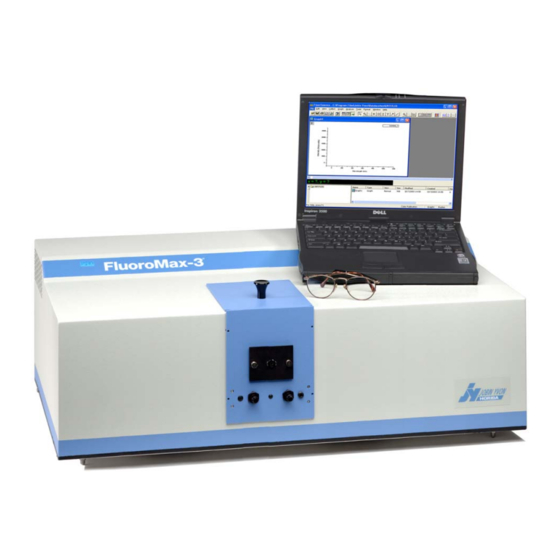
FluoroMax-3 v. 3.1 (3 Mar 2006) Introduction 0: Introduction ® ® About the FluoroMax -3 and FluoroMax ® ® Both the FluoroMax -3 and FluoroMax -P are self-contained, fully automated spectro- fluorometer systems. Data output is viewed on a PC, while printouts may be obtained ®... -
Page 8: Chapter Overview
FluoroMax-3 v. 3.1 (3 Mar 2006) Introduction Chapter overview 1: Requirements & Installation Power and environmental requirements; select the best spot for the instrument. 2: System Description ® How the FluoroMax -3 and -P work. 3: System Operation Operation of the spectrofluorometer system, and calibration instructions. -
Page 9: Disclaimer
HORIBA Jobin Yvon is also under constant development and subject to change without notice. Any warranties and remedies with respect to our products are limited to those provided in writing as to a particular product. In no event shall HORIBA Jobin Yvon be held li-... - Page 10 HORIBA Jobin Yvon is also in no event liable for damages on any theory of liability arising out of, or in connection with, the use or performance of our hardware or software, regard- less of whether you have been advised of the possibility of damage.
-
Page 11: Safety Summary
Failure to comply with these precautions or with specific warn- ings elsewhere in this manual violates safety standards of design, manufacture and in- tended use of instrument. HORIBA Jobin Yvon assumes no liability for the customer’s failure to comply with these requirements. Certain symbols are used throughout the text for special conditions when operating the instruments: A WARNING notice denotes a hazard. - Page 12 FluoroMax-3 v. 3.1 (3 Mar 2006) Introduction Explosion hazard! Wear explosion-proof gog- gles, full-face shield, skin-protection clothing, Warning: and protective gloves. Risk of electric shock! This symbol warns the user that uninsulated voltage within the unit Warning: may have sufficient magnitude to cause electric shock.
- Page 13 FluoroMax-3 v. 3.1 (3 Mar 2006) Introduction Wear appropriate safety goggles to protect the eyes. Wear an appropriate face-shield to protect the face. General information is given concerning opera- Note: tion of the equipment.
-
Page 14: Risks Of Ultraviolet Exposure
FluoroMax-3 v. 3.1 (3 Mar 2006) Introduction Risks of ultraviolet exposure Caution: This instrument is used in conjunction with ul- traviolet light. Exposure to these radiations, even re- flected or diffused, can result in serious, and sometimes irreversible, eye and skin injuries. - Page 15 FluoroMax-3 v. 3.1 (3 Mar 2006) Introduction duced. This should not lessen the concern over lens damage however, because cata- racts are the direct result of lens damage. Burns to the eyes are usually more painful and serious than a burn to the skin. Make sure your eye protection is appropriate for this work.
-
Page 16: Additional Risks Of Xenon Lamps
FluoroMax-3 v. 3.1 (3 Mar 2006) Introduction Additional risks of xenon lamps Warning: Xenon lamps are dangerous. Please read the fol- lowing precautions. Among the dangers associated with xenon lamps are: • Burns caused by contact with a hot xenon lamp. - Page 17 FluoroMax-3 v. 3.1 (3 Mar 2006) Introduction • IR-C (far IR) (3000 nm–1 mm) The skin and eyes absorb infrared radiation (IR) as heat. Workers normally notice ex- cessive exposure through heat sensation and pain. Infrared radiation in the IR-A that enters the human eye will reach (and can be focused upon) the sensitive cells of the ret- ina.
- Page 18 FluoroMax-3 v. 3.1 (3 Mar 2006) Introduction 0-12...
-
Page 19: 1: Requirements & Installation
• Handling xenon-lamp bulbs, and their dangers • Safe handling for all chemicals and other samples used in the instrument ® Safety-training may be purchased from HORIBA Jobin Yvon. Contact your Spex Fluorescence Representative or the Fluorescence Service Department for details. -
Page 20: Surface Requirements
FluoroMax-3 v. 3.1 (3 Mar 2006) Requirements & Installation Surface requirements • A sturdy table- or bench-top. • Surface must hold 90 kg (200 lbs.). • Surface should be about 27" × 72" (69 cm × 183 cm) to hold spectrofluorometer, computer, and accessories comfortably. -
Page 21: Environmental Requirements
FluoroMax-3 v. 3.1 (3 Mar 2006) Requirements & Installation Environmental requirements • Temperature 59–86°F (15–30°C) • Maximum temperature fluctuation ± 2°C • Ambient relative humidity < 75% Caution: Excessive humidity can damage the optics. • Low dust levels • No special ventilation... -
Page 22: Electrical Requirements
FluoroMax Each of certain accessories, such the MicroMax, temperature bath, etc. Warning: HORIBA Jobin Yvon Inc. is not liable for damage from line surges and voltage fluctuations. A surge protector is strongly recommended for mi- nor power fluctuations. For more severe voltage variations, use a generator or uninterruptible power supply. -
Page 23: Unpacking And Installation
For this rea- son, the original packing material should be retained as evidence of alleged mishandling or abuse. While HORIBA Jobin Yvon Inc. as- sumes no responsibility for damage occurring during transit, the com- pany will make every effort to aid and advise. - Page 24 Adjust the four leveling feet on the bottom of the instrument. Inspect for previously hidden damage. Notify the carrier and HORIBA Jobin Yvon Inc. if any is found. Check the packing list to verify that all components and accessories are present.
- Page 25 The information gathered by the spectrofluorometer system is displayed and controlled through the host PC via FluorEssence™ software. The host PC may be purchased from HORIBA Jobin Yvon Inc. or another supplier. ® Set up the host PC reasonably close to the FluoroMax -3 system.
- Page 26 Windows™ environment. If the computer and software were purchased from HORIBA Jobin Yvon Inc., the software installa- tion is complete. If the computer is not from HORIBA Jobin Yvon Inc., perform the installation. Contact a HORIBA Jobin Yvon Inc. Sales Representative for recommended specifications for a suitable host computer.
-
Page 27: Software Emulation
FluoroMax-3 v. 3.1 (3 Mar 2006) Requirements & Installation Software emulation Emulating the FluorEssence™ software means letting the computer act as though the ® FluoroMax is properly connected, even if it isn’t. Disconnect the communications cable from the ® host computer to the FluoroMax Note: Be sure the FluorEssence™... - Page 28 FluoroMax-3 v. 3.1 (3 Mar 2006) Requirements & Installation Choose the desired instrument you wish to emulate. Click OK. The System Initialization Process window opens: Under the Status column, warning symbols appear for the hardware devices, noting that they were Not Found.
-
Page 29: 2: System Description
FluoroMax-3 v. 3 (22 Feb 2005) System Description 2: System Description Warning: Do not open the instrument without proper training and having read this operation manual. The instrument contains dan- gerous voltages, ultraviolet, visible, and infrared radiation, and fragile light-sources. In addition, tampering with the optical com- ponents can irreversibly damage them. -
Page 30: Optical Layout
FluoroMax-3 v. 3 (22 Feb 2005) System Description Optical layout Xenon arc-lamp and lamp housing Xenon-lamp power supply ® Xenon flash lamp (FluoroMax -P only) Excitation monochromator Sample compartment Emission monochromator Signal detector (photomultiplier tube and housing) Reference detector (photodiode and current-acquisition module) - Page 31 FluoroMax-3 v. 3 (22 Feb 2005) System Description ® In the FluoroMax -P, a second source, a xenon flash lamp, is available also. A FluorEs- sence™-controlled motor and gearbox rotate the mirror in the illumination area, in or- der to switch between the CW source and the flash lamp.
- Page 32 FluoroMax-3 v. 3 (22 Feb 2005) System Description tor’s slits control the intensity of the fluorescence signal recorded by the signal detec- tor. When setting slit width, the trade-off is intensity of signal versus spectral resolu- tion. The wider the slits are, the more light falls on the sample and detector, but the resolution decreases.
- Page 33 FluoroMax-3 v. 3 (22 Feb 2005) System Description To insert or remove a sample platform, If a multiple-sample turret is installed, shut off the system. Remove the four screws on the front of the sample platform. Slide out the old platform.
- Page 34 Both the reference and signal detectors have correction-factor files run for them, to cor- rect for wavelength dependencies of each optical component. The files are created at HORIBA Jobin Yvon Inc. for every instrument, and may be applied to data through FluorEssence™. See Chapter 8 for more details.
- Page 35 FluoroMax-3 v. 3 (22 Feb 2005) System Description • Xenon-lamp power This supply is a tunable 180-W-maximum power supply. It supplies a large start-up voltage to the 150-W xenon supply (1a) lamp, then holds the lamp steady at 12 V. The voltage is filtered, to stabilize the illumination as much as possible.
- Page 36 FluoroMax-3 v. 3 (22 Feb 2005) System Description...
-
Page 37: 3: System Operation
An hour meter is mounted on the lower right-hand side, to monitor total usage of the xenon lamp. Note: Each time the xenon lamp is ignited adds one more hour to lamp use. HORIBA Jobin Yvon Inc. suggests leaving the lamp on between brief periods of inactivity. -
Page 38: Turning On The System
FluoroMax-3 v. 3.1 (3 Mar 2006) System Operation Turning on the system Warning: When the xenon lamp is ignited, a large voltage is applied across the lamp. This voltage spike can return along the electrical power cord, causing damage to computer equipment, if the host computer is already on. -
Page 39: Checking System Performance
Use the Performance Test Report to vali- date the spectral shape and relative intensity taken during the calibration checks. Note: HORIBA Jobin Yvon Inc. is not responsible for customer errors in calibration. To be sure that your instrument is properly calibrated, ®... - Page 40 FluoroMax-3 v. 3.1 (3 Mar 2006) System Operation Excitation calibration check This calibration check verifies the wavelength calibration of your excitation mono- chromator, using the reference photodiode located before the sample compartment. It is an excitation scan of the xenon lamp’s output, and should be the first check performed.
- Page 41 FluoroMax-3 v. 3.1 (3 Mar 2006) System Operation Use the default parameters or adjust them. Default monochromator parameters for the xenon-lamp scan Monochromator Initial wave- Final wave- Increment Slits (bandpass) (1200 length length grooves/mm) Excitation 200 nm 600 nm 1 nm...
- Page 42 FluoroMax-3 v. 3.1 (3 Mar 2006) System Operation calibration structure ~ 450 nm peak at 467 broadband This is an uncalibrated ® Note: FluoroMax Your lamp scan may appear different, lamp scan. The depending on the instrument configuration. main peak ought to be at 467 nm, but here appears near 480 nm.
- Page 43 FluoroMax-3 v. 3.1 (3 Mar 2006) System Operation Cursor Wave- length in This example shows the peak actually at 477 nm, which is 10 nm too high. Therefore we must recalibrate the monochromator. Click the Previous Experiment button. The Experiment Setup window appears.
- Page 44 FluoroMax-3 v. 3.1 (3 Mar 2006) System Operation Click the RTC button on the lower right. The Real Time Control window opens. Click the Monos icon to view the monochromators’ index card, then click the excitation monochromator tab.
- Page 45 FluoroMax-3 v. 3.1 (3 Mar 2006) System Operation Enter the current, observed position of the peak in the Position Control (here, 477 nm). Click the Calibrate Excitation 1 button. Calibrate window opens: In Peak Of Interest, enter the actual or expected position of the peak (it ought to be 467 nm).
- Page 46 FluoroMax-3 v. 3.1 (3 Mar 2006) System Operation Emission calibration check Note: The emission calibration of the instrument is directly affected by the calibration of the excitation monochromator. This calibration check verifies the wavelength calibration of the emission monochroma- tor with the emission photomultiplier tube. It is an emission scan of the Raman-scatter band of water performed in right-angle mode.
- Page 47 FluoroMax-3 v. 3.1 (3 Mar 2006) System Operation Choose Spectra. The Experiment Type window appears: Choose Emission. The water-Raman experiment automati- cally loads. 3-11...
- Page 48 FluoroMax-3 v. 3.1 (3 Mar 2006) System Operation Use the default parameters or adjust them. Monochromator parameters for the water-Raman scan: Monochromator Initial wave- Final wave- Incre- Slits (band- (1200 grooves/mm) length length ment pass) Excitation 350 nm 5 nm...
- Page 49 FluoroMax-3 v. 3.1 (3 Mar 2006) System Operation Note: Observed throughput (and hence peak intensity) is af- fected by lamp age and alignment, slit settings, and sample pu- rity. As the xenon lamp ages, the throughput of the system will decline slowly.
- Page 50 (no signal) to show the overall performance of the instrument. Definitions At HORIBA Jobin Yvon, we define the S/N ratio as the difference of peak and back- ground signal, divided by the square root of the background signal.
- Page 51 44 6 11000 HORIBA Jobin Yvon feels that the first method is correct although it gives a lower S/N. The second method only takes into account the detector noise and the shot noise of the electronics. By using the background total intensity as a measure of noise, the HORIBA Jobin Yvon method is more representative of a real “live”...
- Page 52 They can be run, after the system is switched on each day, to check the calibration ® and performance of the FluoroMax • HORIBA Jobin Yvon Inc. recommends monitoring the number of hours of xenon- lamp use, via the hour meter. • Additionally, you may want to record the water-Raman intensity daily or weekly.
-
Page 53: 4: Data Acquisition
FluoroMax-3 v. 3.1 (3 Mar 2006) Data Acquisition 4: Data Acquisition This chapter presents an introduction to the six special buttons used in FluorEssence™ ® to record and present data with the FluoroMax -3. These buttons, located in FluorEs- sence™’s main window, are:... -
Page 54: Experiment Menu Button
FluoroMax-3 v. 3.1 (3 Mar 2006) Data Acquisition Experiment Menu button The Experiment Menu button chooses an overall type of experiment to run, such as an emission scan, a phosphorimeter scan, a synchronous scan, etc., based on the instru- ment and connected accessories, such as a temperature bath, MicroMax, etc. Only those scans that can be run using the available hardware configuration are active;... - Page 55 FluoroMax-3 v. 3.1 (3 Mar 2006) Data Acquisition Click the Experiment File field, and enter a new file name or select a previously saved file. Verify that experimental parameters are correct. Be sure to check all parameters under all icons in the left-hand column.
-
Page 56: Previous Experiment Setup Button
FluoroMax-3 v. 3.1 (3 Mar 2006) Data Acquisition Previous Experiment Setup button The Previous Experiment Setup button resets the experiment to the previous experi- ment used, with minor modifications to the hardware possible. Note: The Previous Experiment Setup button is active only after an experiment has already been loaded. -
Page 57: Auto Run Previous Experiment Button
FluoroMax-3 v. 3.1 (3 Mar 2006) Data Acquisition Auto Run Previous Experiment button The Auto Run Previous Experiment Note: The Auto Run Previous Experiment but- button reruns the last ton is active only after an experiment has al- experiment loaded ready been loaded and run. -
Page 58: Make Overlay File Button
FluoroMax-3 v. 3.1 (3 Mar 2006) Data Acquisition Make Overlay File button The Make Overlay File button creates an Note: The Make Overlay File button is active *.SPC file for use as only with an active graph. an overlay file. -
Page 59: 3D Scan To 3D Profile Button
FluoroMax-3 v. 3.1 (3 Mar 2006) Data Acquisition 3D Scan to 3D Profile button The 3D Scan to 3D Profile button extracts emission profiles from Note: The 3D Scan to 3D Profile button only an excitation-emission operates with excitation-emission matrix data. - Page 60 FluoroMax-3 v. 3.1 (3 Mar 2006) Data Acquisition Click the Arbitrary Line button to choose an arbi- trary profile. Grab an end of the profile line and move to the desired location on the matrix. The profiles are updated. To return to perpendicular profiles, click the...
-
Page 61: Get Peak Information Button
FluoroMax-3 v. 3.1 (3 Mar 2006) Data Acquisition Get Peak Information button The Get Peak Information button shows the full width at half-maximum for the chosen peak, plus Note: The Get Peak other parameters for that peak. Information button only operates with Open a data-set. -
Page 62: Running An Unknown Sample
FluoroMax-3 v. 3.1 (3 Mar 2006) Data Acquisition Running an unknown sample Often a researcher will scan a sample whose spectral characteristics are unknown. For optimal spectra, the optimal excitation and emission wavelengths must be found. The optimal excitation wavelength is the wavelength that creates the most intense emis- sion spectrum for a given sample. - Page 63 Set the scan parameters. Most of these parameters are a trade-off between speed and precision. Choose integration time, increments, and number of scans judiciously, to give an accu- rate result without excessive time spent. HORIBA Jobin Yvon suggests an in- 4-11...
- Page 64 FluoroMax-3 v. 3.1 (3 Mar 2006) Data Acquisition crement of 1.0 nm, an integration time of 0.1–0.5 s, and one scan. If unsure of an excitation wavelength, try 300 nm, at which many samples absorb light. Use S (signal detector) for the acquisition mode. Don’t forget a data file name.
- Page 65 FluoroMax-3 v. 3.1 (3 Mar 2006) Data Acquisition Choose Spectra. The Experiment Type menu appears. Choose Excitation. Click Next >>. The Experiment Setup window appears: 4-13...
- Page 66 FluoroMax-3 v. 3.1 (3 Mar 2006) Data Acquisition Set the scan parameters. Use the emission maximum determined above for the excitation, use 250 nm for starting, enter the emission maximum minus 15 nm for the end of the scan, and select two acquisition modes, S and S/R.
-
Page 67: 5: Optimizing Data
FluoroMax-3 v. 3.1 (3 Mar 2006) Optimizing Data 5: Optimizing Data Spectra can be enhanced by optimization of data-acquisition. This chapter lists some methods of optimizing sample preparation, spectrofluorometer setup, and data correc- tion to get higher-quality data. Cuvette preparation... -
Page 68: Sample Preparation
4-mL cuvette. If fluorescence is weak or if trace elements are to be determined, HORIBA Jobin Yvon recommends a capillary cell such as our 50-μL or 250-μL optional micro-sample capillary cells, which are spe- cifically designed for a small volume. - Page 69 FluoroMax-3 v. 3.1 (3 Mar 2006) Optimizing Data Dissolved solids Solid Sample Solid samples, such as crystals, sometimes Holder are dissolved in a solvent and analyzed in solution. Solvents, however, may contain organic impurities that fluoresce and mask the signal of interest. Therefore, use high- quality, HPLC-grade solvents.
-
Page 70: Running A Scan On A Sample
FluoroMax-3 v. 3.1 (3 Mar 2006) Optimizing Data Running a scan on a sample Precautions with the Solid Sam- Excitation monochromator ple Holder 60° Avoid placing the front face of the sample so that the excitation beam is reflected directly into the Excitation emission monochromator. - Page 71 FluoroMax-3 v. 3.1 (3 Mar 2006) Optimizing Data Highly opaque samples Highly concentrated and opaque liquids often have problems with self-absorption or complete attenuation of the beam. Intensity measurements with the excitation beam at 90° to the emission beam may not be...
-
Page 72: Measuring The G Factor
FluoroMax-3 v. 3.1 (3 Mar 2006) Optimizing Data Measuring the G factor Include the grating factor, or G factor, whenever polarization measurements are taken. The G factor corrects for variations in polarization wavelength-response for the emis- sion optics and detectors. A pre-calculated G factor may be used when all other ex- perimental parameters are constant. - Page 73 FluoroMax-3 v. 3.1 (3 Mar 2006) Optimizing Data In the Experiment Setup window, click the De- tectors icon. This shows the parameters related to detectors, including the G factor, in the Polarization area. Click the G Factor checkbox to include a G fac- tor in your measurements.
-
Page 74: Improving The Signal-To-Noise Ratio
FluoroMax-3 v. 3.1 (3 Mar 2006) Optimizing Data Improving the signal-to-noise ratio Because of various hardware or software conditions, occasionally it is necessary to op- timize the results of an experiment. The quality of acquired data is determined largely by the signal-to-noise ratio (S/N). - Page 75 FluoroMax-3 v. 3.1 (3 Mar 2006) Optimizing Data Determining the optimum integration time The length of time during which photons are counted and averaged for each data point is referred to as the integration time. An unwanted portion of this signal comes from noise and dark counts (distortion inherent in the signal detector and its electronics when high voltage is applied).
- Page 76 FluoroMax-3 v. 3.1 (3 Mar 2006) Optimizing Data Scanning a sample multiple times Scanning a sample more than once, and averaging the scans together, enhances the S/N. , where n is the number of scans. In general, the S/N improves by n To scan a sample multiple times, Open the Experiment Setup window.
- Page 77 FluoroMax-3 v. 3.1 (3 Mar 2006) Optimizing Data Using the appropriate wavelength increment The increment in a wavelength scan is the spacing, in nm, between adjacent data points. The spacing between the data points affects the resolution of the spectrum, and total time for acquisition.
- Page 78 FluoroMax-3 v. 3.1 (3 Mar 2006) Optimizing Data Selecting the appropriate bandpass The bandpass (wavelength spread) affects the resolution of your spectra. If the band- pass is too broad, narrow peaks separated by a small change in wavelength may be un- resolved.
- Page 79 FluoroMax-3 v. 3.1 (3 Mar 2006) Optimizing Data Smoothing data Smoothing the data improves the appearance of the spectrum. Smoothing, as are most ® post-processing features, is handled by Origin Select Analysis from the main FluorEssence™ menu. A drop-down menu appears.
-
Page 80: Correcting Data
FluoroMax-3 v. 3.1 (3 Mar 2006) Optimizing Data Correcting data Introduction Collecting accurate information about the fluorescent or phosphorescent properties of a sample depends upon several factors: • Equipment specifications • Sample characteristics • Timing considerations. To ensure that the spectra collected indicate the actual properties of the sample and not external conditions, data often must be corrected. - Page 81 Note: Before applying correction factors, HORIBA Jobin Yvon Inc. recommends subtracting the dark counts, and the spectrum of the blank, from the data. See the on-line FluorEssence™ help files for specific instructions.
- Page 82 FluoroMax-3 v. 3.1 (3 Mar 2006) Optimizing Data Choose Preferences, then the Instrument Correction Files icon. The Instrument Correction Files area should display a correction file for the Detector (S or R). If not, click the Insert button, and browse for the desired correction file.
- Page 83 FluoroMax-3 v. 3.1 (3 Mar 2006) Optimizing Data Click the Add >> button to add the corrected signal to the Formulas ta- ble. The corrected signal appears in the Formulas table. Run the experiment with the corrected signal. 5-17...
- Page 84 FluoroMax-3 v. 3.1 (3 Mar 2006) Optimizing Data After acquisition To apply the correction factors after the data have been acquired, multiply the data file by the appropriate correction factor file (mcorrect for the S detector or xcorrect for the R detector).
-
Page 85: 6: Maintenance
100 000 cps, replace it. Replacing the lamp within the recommended time may prevent a catastrophic failure. Each time the lamp is turned on constitutes one full hour of use. Therefore, HORIBA Jobin Yvon Inc. suggests leaving the lamp on during brief periods of inactivity. - Page 86 FluoroMax-3 v. 3.1 (3 Mar 2006) Maintenance Hazards ! Xenon-arc lamps are an explosion hazard. Wear explosion-proof face- shield and protective clothing when opening the lamp housing and han- dling the lamp. ! Disconnect the lamp power supply from the AC power line (mains) while handling lamp leads.
- Page 87 FluoroMax-3 v. 3.1 (3 Mar 2006) Maintenance Remove the instrument cover. Remove the seven Phillips screws (two on each side, and three in the back) from the cover. Lift the cover vertically off the instrument by grasping opposite corners of the cover and raising upward.
- Page 88 FluoroMax-3 v. 3.1 (3 Mar 2006) Maintenance While holding the metal anode (top) portion of the lamp, loosen the height adjustment above the lamp with a 1/8" Allen key, until the lamp is removable. Press down against the spring action.
- Page 89 FluoroMax-3 v. 3.1 (3 Mar 2006) Maintenance posed. Remove the anode cable. Remove the thumbscrew at the cathode end (bottom) of the lamp, leav- ing the post exposed. Remove the cathode cable. Place the old lamp in the top protective cover from the new lamp.
- Page 90 FluoroMax-3 v. 3.1 (3 Mar 2006) Maintenance lamp to the approximate position of the old lamp. Replace the lamp-housing cover. Replace the two screws on the lamp-housing cover. Note: Reconnect all cables Do not replace ® FluoroMax (power, accessories, etc.) cover until the lamp ®...
- Page 91 FluoroMax-3 v. 3.1 (3 Mar 2006) Maintenance Is the peak inten- sity ≥ 300 000 cps? No further adjust- ment is necessary. Adjust the lamp: Continue with the procedure below. Replace the lamp-housing cover. Replace ® the FluoroMax -3 cover.
- Page 92 FluoroMax-3 v. 3.1 (3 Mar 2006) Maintenance Acquire another water Raman scan. Use the same parameters as in step 3. Note the peak intensity. Use the flowchart below. Is the signal within specifica- tions? No further adjust- ment is necessary.
-
Page 93: Electronics
FluoroMax-3 v. 3.1 (3 Mar 2006) Maintenance Electronics In case of the rare chance of system failure, this section is provided to help the user un- derstand the electronics components. Warning: The information in this section does not consti- tute permission to adjust, manipulate, or remove any ®... - Page 94 FluoroMax-3 v. 3.1 (3 Mar 2006) Maintenance tion-modules, and optional trigger input from a TRIG-15/25 accessory. The board has an internal ±15 V DC supply. CTI card Older version CPU board CTI Card Newer version CPU board Monochromator drives and accessory controllers The monochromator drives, drive electronics, and accessory electronics are found on the underside of the optical platform.
- Page 95 FluoroMax-3 v. 3.1 (3 Mar 2006) Maintenance Emission monochro- Excitation monochro- mator control board mator control board Sample compartment Emission monochro- Accessory control Excitation mono- mator direct drive board may be here chromator direct drive Emission power, DC sup- plies, and...
- Page 96 FluoroMax-3 v. 3.1 (3 Mar 2006) Maintenance 6-12...
-
Page 97: 7: Troubleshooting
FluoroMax-3 v. 3.1 (3 Mar 2006) Troubleshooting 7: Troubleshooting ® The FluoroMax -3 system has been designed to operate reliably and predictably. If there is a problem, examine the chart below, and try the steps on the following pages. Problem... - Page 98 FluoroMax-3 v. 3.1 (3 Mar 2006) Troubleshooting Raman band super- Aqueous solutions and Change excitation wavelength to move Raman imposed on fluores- solvents have Raman band away from fluorescence peak, or run a cence scan. bands. blank scan of the solvent and subtract it from the fluorescence spectrum.
-
Page 99: Checking The Fluoromax 'S Bios
FluoroMax-3 v. 3.1 (3 Mar 2006) Troubleshooting ® Checking the FluoroMax ’s BIOS Check by listening to the boot-up sequence. ® About 30 s after switching on the FluoroMax , the instrument beeps. After this initial beep, about 1 min later the instrument emits two more very quiet chirps. - Page 100 FluoroMax-3 v. 3.1 (3 Mar 2006) Troubleshooting Section: “STANDARD CMOS SETUP” Drive C : None Settings to change: Drive D : None Halt On : No Errors Once these values are set, press ESC to return to the main screen.
-
Page 101: Using Diagnostic Spectra
FluoroMax-3 v. 3.1 (3 Mar 2006) Troubleshooting Using diagnostic spectra Often the spectrum reveals information regarding the hardware or software parameters that should be adjusted. The following spectra occur with explanations about problems leading to their appearance. Note: Not all spectra shown in this section were produced using the ®... - Page 102 FluoroMax-3 v. 3.1 (3 Mar 2006) Troubleshooting The following lamp scan spectrum shows poor resolution in the area around the peak. 0.4473 Xenon-lamp peaks are unresolved 0.3355 0.2236 0.1118 Wavelength (nm) Poor lamp scan of 150-W Xe lamp. Note low resolution in the area near the 467-nm peak.
- Page 103 FluoroMax-3 v. 3.1 (3 Mar 2006) Troubleshooting Water Raman spectra Contaminated water Running a water Raman scan helps identify abnormalities caused by accessory prob- lems or miscalibration. The following spectrum is normal: 397 nm Wavelength (nm) Clean water Raman scan.
- Page 104 FluoroMax-3 v. 3.1 (3 Mar 2006) Troubleshooting If a spectrum similar to this is obtained after running a water Raman scan, Rotate the cuvette 90° and rerun the scan. If the problem goes away, then the problem was due to the cuvette surface. Clean or use a different cuvette.
- Page 105 FluoroMax-3 v. 3.1 (3 Mar 2006) Troubleshooting Make sure the cuvette is filled to the proper level. Light should fall on the sample, and the meniscus should not be in the light path. Make sure that the excitation and emission slits are set to the proper widths.
-
Page 106: Further Assistance
FluoroMax-3 v. 3.1 (3 Mar 2006) Troubleshooting Further assistance... ® Read all software and accessory manuals before contacting the Spex Fluorescence Service Department. Often the manuals show the problem’s cause and a method of so- lution. Technical support is available for both hardware and software troubleshooting. - Page 107 FluoroMax-3 v. 3.1 (3 Mar 2006) Troubleshooting Under Help, choose About FluorEssence..This opens the About FluorEs- sence window. The version of the software (both FluorEs- ® sence™ and Origin ) is listed here. Determine the SpectrAcq firmware version. Open the Experiment Setup window: Click the Detectors icon.
- Page 108 FluoroMax-3 v. 3.1 (3 Mar 2006) Troubleshooting Move the mouse over the detectors’ table in the Select area. The SpectrAcq firmware version appears in a small pop-up window: ® If the problem persists or is unlisted, call the Spex Fluorescence Service Department at (732) 494-8660 ×...
-
Page 109: 8: Producing Correction Factors
FluoroMax-3 v. 3.1 (7 Mar 2006) Producing Correction Factors 8: Producing Correction Factors Introduction Gratings, detectors and other spectrometer components have response characteristics that are functions of wavelength. These characteristics are superimposed on spectra, and may yield a potentially misleading trace. For accurate intensity comparisons, such as those required for quantum-yield determinations, spectrometer-response characteris- tics must be eliminated. -
Page 110: Generating Emission Correction Factors
To generate emission correction factors, several items are needed: a standard lamp, ap- propriate holders, and a scatter assembly. HORIBA Jobin Yvon Inc. offers two kits: the Model 1908 Standard Lamp Accessory, and the Model 1908MOD Scatter Assembly. -
Page 111: Calculating Emission Correction Factors
FluoroMax-3 v. 3.1 (7 Mar 2006) Producing Correction Factors Calculating emission correction factors Introduction For more information about the theory and application of radiometric correction, con- sult Accuracy in Spectrophotometry and Luminescence Measurements, Mavrodineau, Schultz, and Menis, NBS Spec. Publ. 378 (1973), especially p. 137, “Absolute Spectro- fluorometry,”... - Page 112 FluoroMax-3 v. 3.1 (7 Mar 2006) Producing Correction Factors Using the Simple Math Tool window Note: under the Analysis menu, divide Naming the file IRR by stdlamp2, and name the mcorrect over- resulting file mcorrect. writes the mcor- rect file supplied mcorrect with the software.
-
Page 113: Calculating Excitation Correction Factors
This can be accomplished by a simple excitation scan with rhodamine-B placed in the sample position. Note: To calibrate the reference detector out to 800 nm, use HORIBA Jobin Yvon’s calibrated photodiode accessory. Fill a cuvette with a solution of rhodamine-B. - Page 114 FluoroMax-3 v. 3.1 (7 Mar 2006) Producing Correction Factors Open the Real Time Control. Set the excitation and emission monochromators to 467 nm and 630 nm, respectively.
- Page 115 FluoroMax-3 v. 3.1 (7 Mar 2006) Producing Correction Factors The largest lamp peak occurs at 467 nm. Set the slit on the excitation monochromator to 0.5 mm. Make sure the shutter is open. Adjust the slit on the emission monochromator (Slits Width field) to obtain a signal intensity of (1 ±...
- Page 116 FluoroMax-3 v. 3.1 (7 Mar 2006) Producing Correction Factors Click the Detectors icon Enable both S1 and R1 detectors. The codes S1 and R1 appear in the Formulas table. Remove both S1 and R1 from the Formulas table. In the Signal column, click S1. In the Operations column, click the division sign, /.
- Page 117 FluoroMax-3 v. 3.1 (7 Mar 2006) Producing Correction Factors As with the corrected emission factors, find the minimum data point and divide the file by that value. Save the normalized file as xcorrect. This overwrites the existing excitation correction-factor file.
-
Page 118: Using Correction-Factor Files
FluoroMax-3 v. 3.1 (7 Mar 2006) Producing Correction Factors Using correction-factor files To use the newly acquired xcorrect and mcorrect files, you must tell FluorEs- sence™ use them when the Correction check box is activated in the Experiment Setup window. - Page 119 FluoroMax-3 v. 3.1 (7 Mar 2006) Producing Correction Factors The Preferences area appears. Choose the Instrument Correction Files icon. The Instrument Correction Files area appears. If there are no active fields in the Instrument Correction Files area, click Insert. In sequence,...
- Page 120 FluoroMax-3 v. 3.1 (7 Mar 2006) Producing Correction Factors Then, in the File column, browse for the appropriate correction-factor file. When all necessary detectors have an associated correction-factor file, click OK. The new correction-factor files are now ready to be activated in the Experiment...
-
Page 121: 9: Fluoromax ® -P Phosphorimeter Operation
® FluoroMax-3 v. 3.1 (6 Mar 2006) FluoroMax -P Phosphorimeter Operation 9: FluoroMax -P Phosphorime- ® ter Operation Introduction ® The FluoroMax -P includes a phosphorimeter, that is, a programmable pulsed source and selectable signal gating from the reference detector. Switching between the pulsed ®... -
Page 122: Theory Of Operation
® FluoroMax-3 v. 3.1 (6 Mar 2006) FluoroMax -P Phosphorimeter Operation Theory of operation A second source of illumination, a pulsed xenon lamp, is used for phosphorescence measurements. Samples are excited with pulsed light; the emitted phosphorescence is measured using an R928P photon-counting detector. - Page 123 ® FluoroMax-3 v. 3.1 (6 Mar 2006) FluoroMax -P Phosphorimeter Operation Parameters involved in phosphorimetry Lamp Lamp pulse pulse Time per flash Initial delay Sample window t = 0 This sequence of excitation, delay, and sampling, is repeated for each lamp flash. The signal is accumulated for a predetermined number of excitation pulses, then FluorEs- sence™...
- Page 124 ® FluoroMax-3 v. 3.1 (6 Mar 2006) FluoroMax -P Phosphorimeter Operation Initial Delay can be varied with time to yield a decay curve. Spec- tra can be scanned to isolate different phosphorescing components based on the lifetime of the luminescent species in the sample. To- gether, these two techniques can be used to create three- dimensional plots.
-
Page 125: Applications For The Phosphorimeter
® FluoroMax-3 v. 3.1 (6 Mar 2006) FluoroMax -P Phosphorimeter Operation Applications for the phosphorimeter Phosphorescence decay curve With the Phos experiment type in the Fluorescence Experiment Menu, create a phospho- rescence-decay curve, as in the screenshot from FluorEssence™ shown above. This is... - Page 126 ® FluoroMax-3 v. 3.1 (6 Mar 2006) FluoroMax -P Phosphorimeter Operation Isolate components in a mixture based on lifetimes To the right are three scans of an aqueous mixture of terbium and europium chlo- rides that isolate different phosphorescent compo- nents based on their life- times.
- Page 127 ® FluoroMax-3 v. 3.1 (6 Mar 2006) FluoroMax -P Phosphorimeter Operation Kinetic analysis of mixtures Often a sample containing a mixture of components can be analyzed through fitting its phosphorescence-decay curve. Here is a phosphorescence decay of an aqueous mixture...
-
Page 128: Operation Of The Phosphorimeter
® FluoroMax-3 v. 3.1 (6 Mar 2006) FluoroMax -P Phosphorimeter Operation Operation of the phosphorimeter Start-up Load an appropriate instrument configuration that includes the phosphorimeter. FluorEssence™ features Experiment Setup window The Experiment Setup window, under the Detectors icon, includes a Phosphorimeter area, indicating that the phosphorimeter is available. - Page 129 ® FluoroMax-3 v. 3.1 (6 Mar 2006) FluoroMax -P Phosphorimeter Operation These are similar to the standard excitation, and emission synchronous Excitation scans. Among the changes are that the Integration Time field is removed, Emission and instead are data-entry fields for Sample window, Delay after flash, Time per flash, and Flash count.
-
Page 130: Processing Phosphorimeter Data
® FluoroMax-3 v. 3.1 (6 Mar 2006) FluoroMax -P Phosphorimeter Operation Processing phosphorimeter data Open the graph to be processed. Click on the data points to be processed. In the toolbar, choose Analysis. A drop-down menu appears. Choose Fit. From the sub-... -
Page 131: Lamp Replacement
® FluoroMax-3 v. 3.1 (6 Mar 2006) FluoroMax -P Phosphorimeter Operation Lamp replacement The xenon flash lamp typically has a half-intensity life of at least 10 million flashes. Follow the procedure below for replacement and alignment. Warning: ® High voltage exists within the FluoroMax To avoid fatal shocks, before removing the lamp cover, ®... - Page 132 ® FluoroMax-3 v. 3.1 (6 Mar 2006) FluoroMax -P Phosphorimeter Operation Hazards Xenon-arc lamps are an explosion hazard. Wear explosion-proof face-shield and protective clothing when opening the lamp housing and handling the lamp. Disconnect the lamp power supply from the AC power line (mains) while han- dling lamp leads.
- Page 133 ® FluoroMax-3 v. 3.1 (6 Mar 2006) FluoroMax -P Phosphorimeter Operation Gently slide the sample mount out of the instrument. Some sample mounts have a 15-pin connector at the inside end for automated accessories. Remove the instrument cover. Remove the seven Phillips screws (two on each side, and three in the back) from the cover.
- Page 134 ® FluoroMax-3 v. 3.1 (6 Mar 2006) FluoroMax -P Phosphorimeter Operation Discard the old flash lamp in a safe and appropriate manner. Insert the new flash lamp. Warning: Never touch the flash lamp’s glass bulb with bare hands. The oils from your hands can weaken the bulb and cause catastrophic failure.
-
Page 135: 10: Automated Polarizers
FluoroMax-3 v. 3.1 (6 Mar 2006) Automated Polarizers 10: Automated Polarizers Introduction Theory The measurement of polarized emission of fluorescence allows the observation of rota- tional motions in fluorophores during the lifetime of the excited state. Because the rota- tion of macromolecules depends on their size, shape, and local environment (i.e., sol- vent), several kinds of information may be extracted. - Page 136 FluoroMax-3 v. 3.1 (6 Mar 2006) Automated Polarizers ented polarizers (H) are said to be at 90°. Polarization and anisotropy are expressed as follows: − − In a real optical system, the G, or grating factor, must be included to correct for the wavelength response to polarization of the emission optics and detectors.
- Page 137 FluoroMax-3 v. 3.1 (6 Mar 2006) Automated Polarizers − For single-photon excitation, the allowed values for the emission anisotropy are gov- erned by: α = 0 4 (cos ) − ( ) = where P x is the second Legendre polynomial, and α is the angle between the molecule’s absorption and emission dipoles.
- Page 138 FluoroMax-3 v. 3.1 (6 Mar 2006) Automated Polarizers Excitation Excitation Light Polarizer Excitation and Emission Polarizers are rotated to give both components V and H. Emission Polarizer An L-format polarization measurement is illustrated schematically in Figure 1. The excitation polarizer is...
-
Page 139: Installation
FluoroMax-3 v. 3.1 (6 Mar 2006) Automated Polarizers Installation ® Spex polarizers are made for easy installation and removal from the light path. All of the polarizers use pinned collars to hold the polarizers in their mounts and maintain calibration when the polarizers are removed. -
Page 140: Alignment
FluoroMax-3 v. 3.1 (6 Mar 2006) Automated Polarizers Alignment Checking polarizer alignment Polarizer alignment is verified by measuring the anisotropy of a dilute scattering solu- tion. Scattered light is highly polarized, and this allows a simple check of the crystal alignment in the instrument. - Page 141 FluoroMax-3 v. 3.1 (6 Mar 2006) Automated Polarizers Apply the proper voltage on S (950 V for an R928P photomultiplier). Open the excitation shutter (if applicable). Click the Accessories icon. Set both polarizers to VV (0°). Check the signal on S. Set slits evenly for each monochromator to result in 1–1.5 million cps on...
- Page 142 FluoroMax-3 v. 3.1 (6 Mar 2006) Automated Polarizers Re-alignment of polarizers ® FluoroMax -3 autopolarizers may be aligned using a software routine called Polarizer Alignment in Experiment Setup . Using Polarizer Alignment ® This routine automatically calibrates autopolarizers. Use a sample of LUDOX or gly- cogen to run the alignment routine.
- Page 143 FluoroMax-3 v. 3.1 (6 Mar 2006) Automated Polarizers Choose various options: • Subtract Dark (recommended) • Reset to Mechanical Zero —only if the polarizers are definitely miscalibrated. This deletes the Note: Do not previous calibration. check the Re- measure Anisot- ®...
- Page 144 FluoroMax-3 v. 3.1 (6 Mar 2006) Automated Polarizers When complete, the software routine displays the measured anisotropy for each emission channel ( S or T ). Approve or retry the measurement based on satisfaction with the result. To quit, hit the Cancel button at any time during the procedure.
- Page 145 FluoroMax-3 v. 3.1 (6 Mar 2006) Automated Polarizers ® Insert the LUDOX or glycogen sample into the sample holder. Warning: Read the Materials Safety Data Sheets (MSDS) before using colloidal silica or glycogen. Start the software (if not yet running) and go to...
- Page 146 FluoroMax-3 v. 3.1 (6 Mar 2006) Automated Polarizers Open the excitation shutter (if applicable). Turn on high voltage and set appropriately for S channel (950 V for R928P; 1050 V for R1527). Set slits to 5-nm bandpass for all monochroma- tors.
- Page 147 FluoroMax-3 v. 3.1 (6 Mar 2006) Automated Polarizers Set polarizers to VV. Reset slits for 1–1.5 × 10 cps on S channel. Measure polarization ratio (Equation 9). If the polarization ratio > 100, then the alignment is acceptable. Otherwise, repeat steps 15–18.
-
Page 148: Using Automated Polarizers
FluoroMax-3 v. 3.1 (6 Mar 2006) Automated Polarizers Using automated polarizers ® FluorEssence™ software with Spex polarizers provides many choices for polarization measurements. Depending on the accessories, the opportunity exists to remove polari- zation effects from the sample, measure the polarization characteristics, or analyze the decay of anisotropy using frequency-domain techniques. - Page 149 FluoroMax-3 v. 3.1 (6 Mar 2006) Automated Polarizers Using FluorEssence™ To use the autopolarizers, load an instrument configuration with autopolarizers. Real Time Control Real Time Control manipulates the polarizers and other instrument settings, to observe and optimize the spectrofluorometer in real time. Under the Accessories icon, each polarizer may be set independently into or out of the optical path under its own index- card tab.
- Page 150 FluoroMax-3 v. 3.1 (6 Mar 2006) Automated Polarizers Experiment Setup Experiment Setup runs all scanning options for the autopolarizers. First choose the type of scan using polar- izers in the Fluorescence Main Ex- periment Menu: The Experiment Setup window appears.
- Page 151 FluoroMax-3 v. 3.1 (6 Mar 2006) Automated Polarizers Constant Wavelength Analysis To do a constant-wavelength analysis experiment, that is, to take polariza- tion acquisitions at fixed excita- tion/emission wavelength-pairs, choose Anisotropy from the Fluo- rescence Main Experiment Menu . The Experiment Type window opens.
- Page 152 FluoroMax-3 v. 3.1 (6 Mar 2006) Automated Polarizers Make sure to use the appropriate Signal in the Signal Algebra area. Add >> it to the Formulas table. Click the checkbox to measure G factor (s) during the scan, or specify G-factor(s) beforehand in the field.
-
Page 153: Maintenance
FluoroMax-3 v. 3.1 (6 Mar 2006) Automated Polarizers Maintenance Like all optics, polarizers should be handled with care and stored properly. With proper care, a polarizer should last for many years. Aside from installation, removal, and stor- age, there is no routine maintenance necessary for a polarizer. Polarizers should be re- moved and stored when not in use. -
Page 154: Troubleshooting
Troubleshooting For difficulties with polarizers, consult the table below to see if your question is an- swered here. Otherwise, reach Fluorescence Service at HORIBA Jobin Yvon by phone, fax, or e-mail. Before contacting us, please follow the instructions below: Note the problem and record any error mes- sages. - Page 155 FluoroMax-3 v. 3.1 (6 Mar 2006) Automated Polarizers Problem Cause Possible Remedy Improper sample concen- Adjust sample concentration. Poor polarization data tration Photomultiplier saturated; Check that sample signals are slits improperly set in linear region (< 2 × 10 on S or T, < 10 µA on R). Re- set slits.
- Page 156 FluoroMax-3 v. 3.1 (6 Mar 2006) Automated Polarizers 10-22...
-
Page 157: 11: Technical Specifications
FluoroMax-3 v. 3.1 (6 Mar 2006) Technical Specifications 11: Technical Specifications ® Each FluoroMax -3 system consists of: • An excitation source • An excitation monochromator • A sampling module with reference detector • An emission monochromator • An emission detector. -
Page 158: Spectrofluorometer System
FluoroMax-3 v. 3.1 (6 Mar 2006) Technical Specifications Spectrofluorometer system ® ® FluoroMax -3 and FluoroMax ® ® The FluoroMax -3 and FluoroMax -P spectrofluorometers consist of components con- ® trolled by the specialized software. The basic (standard) FluoroMax -3 and Fluoro- ®... - Page 159 FluoroMax-3 v. 3.1 (6 Mar 2006) Technical Specifications Dimensions 5.5" wide × 7" high × 7" long 14.0 cm wide × 17.8 cm high × 17.8 cm long (sample com- partment only) Weight 75 lbs (34 kg) Ambient tem- 15–30°C (59–86°F)
-
Page 160: Minimum Computer Requirements
FluoroMax-3 v. 3.1 (6 Mar 2006) Technical Specifications Minimum computer requirements Microprocessor Pentium IV or higher recommended Operating system and envi- Windows™ 2000 or XP Pro ronment Floppy drive 1.4 MB, 3½" floppy-disk drive Hard disk At least 80 GB of free storage... -
Page 161: 12: Components & Accessories
FluoroMax-3 v. 3.1 (7 Mar 2006) Components & Accessories 12: Components & Accessories ® Accessories for the FluoroMax -3 can be added to obtain optimum results for a variety of applications. The following list represents all the accessories and components, in al- ®... -
Page 162: Itemized List Of Fluoromax ® -3 Accessories
FluoroMax-3 v. 3.1 (7 Mar 2006) Components & Accessories ® Itemized list of FluoroMax -3 accessories Item Model Page Accessory, absorption/transmission 1940 12-3 Adapter, micro cell (See Cell, micro) 1923A Adapter, micro cell (See Cell, micro) 1924A Assembly, liquid-nitrogen Dewar... -
Page 163: Model 1940 Absorption/Transmission Accessory
FluoroMax-3 v. 3.1 (7 Mar 2006) Components & Accessories Model 1940 Absorption/Transmission Accessory The Model 1940 Absorption/Transmission Accessory slightly displaces the sample from its normal position and directs the transmitted light into the collection optics with a mirror mounted at 45°. - Page 164 FluoroMax-3 v. 3.1 (7 Mar 2006) Components & Accessories Note the emission signal at maximum transmission of the blank. Adjust the slits to maximize the signal Note: The linear range of the without saturating R928P detector operated in the photon-counting mode is the detector.
- Page 165 FluoroMax-3 v. 3.1 (7 Mar 2006) Components & Accessories Acquire a synchronous scan with an offset of 0 nm over the absorption range of the blank. Note: If the detectors are saturated, close the slits a Acquire a synchronous scan...
-
Page 166: Fl-1013 Liquid Nitrogen Dewar Assembly
FluoroMax-3 v. 3.1 (7 Mar 2006) Components & Accessories FL-1013 Liquid Nitrogen Dewar Assembly Warning : Refer to your Material Safety Data Sheet (MSDS) for information on the hazards of cryogenic materials such as liquid nitrogen. For phosphorescence or delayed fluorescence... -
Page 167: Model 1908Mod Scatter Block Assembly
FluoroMax-3 v. 3.1 (7 Mar 2006) Components & Accessories Model 1908MOD Scatter Block Assembly The 1908MOD Scatter Block Assembly includes a white scatter block assembly and a clamp holder for use with a user- supplied standard lamp and regulated power supply. -
Page 168: Sample Cells
FluoroMax-3 v. 3.1 (7 Mar 2006) Components & Accessories Sample cells Model 1955 HPLC Flow Cell With a sample capacity of 20 μL, this non-fluorescing fused silica cell is ideal for on-line monitoring of fluorescent samples. The cell maintains high sensitivity because... -
Page 169: F-3000 Fiber Optic Mount
FluoroMax-3 v. 3.1 (7 Mar 2006) Components & Accessories F-3000 Fiber Optic Mount Now you can study marine environments, skin and hair, or other large samples in situ! For those users who want to examine samples unable to be inserted into the sample compartment, the F-3000 Fiber Optic Mount (plus fiber-optic bundles) allows remote sensing of fluorescence. -
Page 170: Model 1938 Cut-On Filter
FluoroMax-3 v. 3.1 (7 Mar 2006) Components & Accessories Model 1938 Cut-On Filter The Model 1938 Cut-On Filter Set consists of five 1" × 2" filters. To position the filter properly, the Model FL-1010 Filter Holder is required. Cut-on filters are used to eliminate 2 -order effects of the gratings. -
Page 171: Fl-1010 Cut-On Filter Holder
FluoroMax-3 v. 3.1 (7 Mar 2006) Components & Accessories FL-1010 Cut-On Filter Holder Cut-on filters are used to eliminate second-order effects of the gratings. The sample compartment has three slots that can hold the FL-1010 Fil- ter Holder. Refer to either... -
Page 172: Fl-1011 Four-Position Thermostatted Cell Holder
FluoroMax-3 v. 3.1 (7 Mar 2006) Components & Accessories FL-1011 Four-Position Thermostatted Cell Holder The FL-1011 Four-Position Thermostatted Cell Holder keeps a sample at a constant temperature from –20°C to +80°C. The temperature is maintained by an ethylene- glycol–water mixture pumped through from an external circulating temperature bath (not included). - Page 173 FluoroMax-3 v. 3.1 (7 Mar 2006) Components & Accessories Place the sample in a 10 mm × 10 mm cuvette and insert a magnetic stirring bar. (The stirring bar is available from Bel-Art Products, Pequannock, NJ) Place a cuvette in each holder.
-
Page 174: Fl-1012 Dual-Position Thermostatted Cell Holder
FluoroMax-3 v. 3.1 (7 Mar 2006) Components & Accessories FL-1012 Dual-Position Thermostatted Cell Holder The FL-1012 Dual-Position Thermostatted Cell Holder keeps a sample at a constant temperature from –20°C to +80°C. The temperature is maintained by an ethylene- glycol–water mixture pumped through from an external circulating temperature bath (not included). - Page 175 FluoroMax-3 v. 3.1 (7 Mar 2006) Components & Accessories Place your sample in a 10 mm × 10 mm cuvette and insert a magnetic stirring bar. (The stirring bar is available from Bel-Art Products, Pequannock, NJ) Place a cuvette in each holder.
-
Page 176: Model 1933 Solid Sample Holder
FluoroMax-3 v. 3.1 (7 Mar 2006) Components & Accessories Model 1933 Solid Sample Holder The Model 1933 Solid Sample Holder is designed for samples such as thin films, pow- ders, pellets, microscope slides, and fibers. The holder consists of a base with a dial in- dicating angle of rotation, upon which a bracket, a spring clip, and a sample block rest. - Page 177 FluoroMax-3 v. 3.1 (7 Mar 2006) Components & Accessories Note: When the sample is perpendicular the light is collected at an angle of 22.5°. This orientation minimizes stray and reflected light off the sur- face of the sample. For samples such as thin films, microscope slides,...
-
Page 178: F-3005/6 Autotitration Injector
FluoroMax-3 v. 3.1 (7 Mar 2006) Components & Accessories F-3005/6 Autotitration Injector For controlled, automatic injection of aliquots into the sample of your choice, the F- 3005/6 Autotitration Injector is just the thing, available in both 110-V (F-3005) and 220-V (F- 3006) models. -
Page 179: Microscope Interface
FluoroMax-3 v. 3.1 (7 Mar 2006) Components & Accessories Microscope Interface The Microscope Interface eases the use ® of the FluoroMax -3 systems for fluo- rescence-microscopy measurements. The accessory includes fiber-optics to bring excitation light to the micro- scope’s stage and emission light to the... -
Page 180: Model 1905-Ofr 150-W Xenon Lamp
FluoroMax-3 v. 3.1 (7 Mar 2006) Components & Accessories Model 1905-OFR 150-W Xenon Lamp The Model 1905 150-W xenon lamp delivers light from 240 nm to 850 nm for sample excitation. The lamp has an approximate life of 1500 hours, and is ozone-free. -
Page 181: F-3004 Sample Heater/Cooler Peltier Thermocouple Drive
FluoroMax-3 v. 3.1 (7 Mar 2006) Components & Accessories F-3004 Sample Heater/Cooler Peltier Thermocouple Drive For rapid control of the sample’s temperature in the ® FluoroMax -3’s sample compartment, choose the F- 3004 Peltier Drive. Instead of messy fluids, the Peltier... -
Page 182: Fm-2005 Phosphorimeter Upgrade
FluoroMax-3 v. 3.1 (7 Mar 2006) Components & Accessories FM-2005 Phosphorimeter upgrade To perform phosphorescence measurements using the ® FluoroMax -3, order the FM-2005 upgrade. This accessory, which ® converts the FluoroMax -3 into a ® FluoroMax -P, offers automated... -
Page 183: Micromax 384 Microwell Plate Reader
FluoroMax-3 v. 3.1 (7 Mar 2006) Components & Accessories MicroMax 384 Microwell Plate Reader The MicroMax 384 Microwell Titer-Plate Reader allows multiple samples to be scanned in one experiment. The MicroMax 384 is controlled through the FluorEs- sence™ software via a serial port to the host computer. The titer plate moves beneath a stationary optical beam, and fluorescence measurements are collected with top-reading geometry. -
Page 184: Fl-1044 L-Format Polarizer
FluoroMax-3 v. 3.1 (7 Mar 2006) Components & Accessories FL-1044 L-Format Polarizer For L-format spectrofluorometers ® such as the FluoroMax -3, the FL-1044 dual polarizer is ideal. The kit includes two polarizers, to be placed at the entrance and the exit of the T-box. -
Page 185: Fl-1015 Injector Port
FluoroMax-3 v. 3.1 (7 Mar 2006) Components & Accessories FL-1015 Injector Port For the study of reaction kinetics, such as Ca measurements, the FL-1015 Injector Port is ideal. This accessory allows additions of small volumes via a syringe or pipette to the sample cell without removing the lid of the sample compartment. -
Page 186: Quantum-Yield Accessory
FluoroMax-3 v. 3.1 (7 Mar 2006) Components & Accessories Quantum-Yield accessory ® The integrating sphere is used in the FluoroMax spectrofluorometer to study fluorescence from solid and liquid samples. The sphere has an internal diameter of 4″ (10 cm). Of special interest is the measurement of photoluminescence quantum yields of such materials, especially for thin solid films. -
Page 187: Sfa-20/Spex Stopped-Flow Accessory
FluoroMax-3 v. 3.1 (7 Mar 2006) Components & Accessories SFA-20/SPEX Stopped-flow accessory The SFA-20/SPEX series of stopped-flow rapid-kinetics accessories offers versatility for spectroscopic monitoring of fast reactions in solution. In addition to the conventional two-syringe mixing system, there is also a three-syringe... -
Page 188: Fm-2013 Tcspc Upgrade
FluoroMax-3 v. 3.1 (7 Mar 2006) Components & Accessories FM-2013 TCSPC upgrade Now you can have the speed and versatility you’ve come to expect in ® the FluoroMax -3, with the bonus of pico- and nanosecond lifetime capability. Time-correlated single-... - Page 189 FluoroMax-3 v. 3.1 (7 Mar 2006) Components & Accessories F-1000/1 Temperature Bath For studies of samples whose properties are temperature-dependent, use the F-1000/1 Temperature Bath. The controller circulates fluids externally, with tubes leading to the sample chamber. The temperature range is from –25°C to +150°C. Sensor and all ca- bles are included with the F-1000/1.
-
Page 190: Model Trig-15/25 External Trigger Accessory
FluoroMax-3 v. 3.1 (7 Mar 2006) Components & Accessories Model TRIG-15/25 External Trigger Accessory The TRIG-15/25 accessory permits the Note: The TRIG-15/25 is fluorescence system to be operated with only used for older almost any external trigger stimulus. Data ®... -
Page 191: Fm-2007 Windows For The Fluoromax
FluoroMax-3 v. 3.1 (7 Mar 2006) Components & Accessories ® FM-2007 Windows for the FluoroMax sample compartment Installing the windows Note: If there are no filter holders, Prepare the mount the FM-2007 Windows on the inside of the sample compart- instrument. - Page 192 FluoroMax-3 v. 3.1 (7 Mar 2006) Components & Accessories Install purge port. Remove plastic original plug, using a 3/16" Allen key. New purge port. Screw in manually the new metal purge port. Tighten with a 7/16" wrench. Remove the plastic cap whenever a hose is to be attached to the new purge port.
-
Page 193: 13: Glossary
FluoroMax-3 v. 3.1 (6 Mar 2006) Glossary 13: Glossary Absorption The electronic transition from the ground state to the excited singlet state, by absorption of a photon of a particular energy. This process –15 typically occurs in ~10 Absorbance The extent of light absorption by a substance, –log T, where T is the transmittance of the sample. - Page 194 FluoroMax-3 v. 3.1 (6 Mar 2006) Glossary Bandpass filter An optical element, which selectively transmits a range of wave- lengths, while absorbing light of higher and lower wavelengths. Bioluminescence Emission of light originating from a chemical reaction in a living or- ganism.
- Page 195 FluoroMax-3 v. 3.1 (6 Mar 2006) Glossary filenames and , respectively. XCORRECT MCORRECT CTI card This acquisition and control card, located in the rear of the Fluoro- ® -3, is the counter-timer-integrator board. It handles all spectro- fluorometer control, timing, and data acquisition for measurements on the system.
- Page 196 FluoroMax-3 v. 3.1 (6 Mar 2006) Glossary monchromator to measure the fluorescence emission. Emission scan An acquisition that shows the spectral distribution of light emitted by a sample. During an emission scan, the excitation spectrometer re- mains at a fixed wavelength while the emission spectrometer scans a user-selected region.
- Page 197 FluoroMax-3 v. 3.1 (6 Mar 2006) Glossary routinely. Extrinsic fluorescence Inherent fluorescence of fluorescent probes added to a system to study non-fluorescent molecules. These probes have gained accep- tance in a variety of applications. Filter An optical element that is used to select certain wavelengths of light.
- Page 198 FluoroMax-3 v. 3.1 (6 Mar 2006) Glossary High-pass filter Optical component that passes light of a higher wavelength. Increment The spacing between adjacent measurement points in an acquisition. Typically, increments take the form of wavelength (nm) or time (s or ms).
- Page 199 FluoroMax-3 v. 3.1 (6 Mar 2006) Glossary Low-pass filter Optical component that passes light of a lower wavelength. Luminescence The emission of light from matter excited from a variety of proc- esses, resulting in an electronic transition within the molecule to a lower energy state.
- Page 200 FluoroMax-3 v. 3.1 (6 Mar 2006) Glossary –6 curs within ~10 to ~1 second. To enhance phosphorescence, sam- ples often are frozen at liquid-nitrogen temperature (77 K). Photobleaching The reduction in fluorescence from a photosensitive sample overly exposed to excitation light. Not all samples photobleach, but if so,...
- Page 201 FluoroMax-3 v. 3.1 (6 Mar 2006) Glossary the same energy as the incident light. The scattered radiation’s inten- sity is inversely proportional to the 4 power of the wavelength of incident radiation. Real Time Control The FluorEssence™ software application that gives the user full con- trol of the system in real-time, in order to optimize the system setup for a particular measurement.
- Page 202 FluoroMax-3 v. 3.1 (6 Mar 2006) Glossary sented as signal to peak-to-peak noise, or signal-to-noise at first stan- dard deviation (FSD). Single Point The FluorEssence™ scan-type designed for performing single-point measurements at discrete wavelength pairs. The data are acquired as single points at a user-defined set of excitation/emission wavelength pairs for a user-defined number of samples.
- Page 203 FluoroMax-3 v. 3.1 (6 Mar 2006) Glossary easy control of assays and complex experiments. Stokes shift The energy difference between the absorption peak of lowest energy and the fluorescence peak of maximum energy. Synchronous scan Scan type characterizing the overlap between the excitation and emission.
- Page 204 FluoroMax-3 v. 3.1 (6 Mar 2006) Glossary Variable time kinetics A special measurement menu in the Single Point experiment type. The user defines measurements that occur at specific times, for spe- cific durations, and with different integration times. Those measuring assays can do the actual measurements at the desired times.
-
Page 205: 14: Bibliography
FluoroMax-3 v. 3.1 (6 Mar 2006) Bibliography 14: Bibliography P.M. Bayley and R.E. Dale, Spectroscopy and the Dynamics of Molecular Biological Systems, Academic Press, London, 1985. R.S. Becker, Theory and Interpretation of Fluorescence and Phosphorescence, Wiley-Interscience, New York, 1969. I.B. Berlman, Handbook of Fluorescence Spectra in Aromatic Molecules, 2 ed., Vols. - Page 206 FluoroMax-3 v. 3.1 (6 Mar 2006) Bibliography M.A. Konstantinova-Schlezinger, ed. Fluorometric Analysis, Davis Publishing Co., New York, 1965. Joseph R. Lakowicz, Principles of Fluorescence Spectroscopy, 2 ed., Plenum Press, New York, 1999. _______, ed., Topics in Fluorescence Spectroscopy, Vols. 1–5, Plenum Press, New York, 1991–1998.
- Page 207 FluoroMax-3 v. 3.1 (6 Mar 2006) Bibliography T. Vo-Dinh, Room Temperature Phosphorimetry for Chemical Analysis, Wiley- Interscience, New York, 1984. I.M. Warner and L.B. McGown, ed., Advances in Multidimensional Luminescence, Vols. 1 & 2, JAI Press, Greenwich, CT, 1991–1993. E.L. Wehry, ed., Modern Fluorescence Spectroscopy, Vol. 1–4, Plenum Press, New York, 1975–1981.
- Page 208 FluoroMax-3 v. 3.1 (6 Mar 2006) Bibliography 14-4...
- Page 209 73/23/EEC as amended by 93/68/EEC. The CE marking has been affixed on the device according to Annex III of the Low Voltage Directive 73/23/EEC. The technical file and other documentation are on file with HORIBA Jobin Yvon Inc. ______________________________ Ray Kaminski...
- Page 210 FluoroMax-3 v. 3.1 (6 Mar 2006) Declaration of Conformity 15-2...
- Page 211 FluoroMax-3 v. 3.1 (25 Apr 2006) Index 16: Index Key to the entries: Times New Roman font ..subject or keyword Arial font ........command, 81038 ............1-5 menu choice, 81106 ............1-5 or data-entry field Arial Condensed Bold font ..dialog box Courier New font....file name or...
- Page 212 FluoroMax-3 v. 3.1 (25 Apr 2006) Index Anisotropy ........5-6, 10-17 FM-2005 ..........12-22 FM-2007 ..........12-31 scan............10-7 FM-2013 ..........12-28 scan-type........5-6, 10-6 Four-Position Thermostatted Cell Holder anthracene..........4-14 Arbitrary Line button ........ 4-8 ............12-12 Injector Port ........12-25 Auto Run Previous Experiment button 4-1, integrated sphere ........12-26...
- Page 213 FluoroMax-3 v. 3.1 (25 Apr 2006) Index corrected data ...........5-14 disclaimer ..........0-3 Correction checkbox..... 5-16, 8-10 dispersion........ 2-4, 5-12, 11-2 correction-factor file ...2-6, 5-14, 5-18, 8-1–5, dissolved solids.......... 5-3 8-9, 8-12, 12-7 DM302............. 6-11 coverslip......... 5-2, 12-16 Dual-Position Thermostatted Cell Holder. 12- CPS ..........
- Page 214 FluoroMax-3 v. 3.1 (25 Apr 2006) Index F-3005 ............12-18 Four-Position Thermostatted Cell Holder . 12- F-3006 ............12-18 face-shield ..........6-2 full width at half-maximum....... 4-9 fans, exhaust..........6-10 fused silica......5-2, 12-6, 12-8 FFT Filtering...........5-13 fiber-optic bundle....2-4, 12-9, 12-23 Fiber Optic Mount........12-9 fiber-optic probe........4-10...
- Page 215 FluoroMax-3 v. 3.1 (25 Apr 2006) Index instrument cover....6-3, 6-6, 9-13–14 integrated sphere ........12-26 M ............10-13 integration time3-5, 3-12, 4-11, 5-8–9, 6-7, 9- 2, 11-2 mA ............3-5, 3-12 macromolecules........10-1 determining optimum......5-9 Integration Time....... 8-8, 9-9 magic angle........10-4, 10-14 magnetic stirrer..
- Page 216 FluoroMax-3 v. 3.1 (25 Apr 2006) Index notice, intense light ........0-5 photon-pulse pile-up........2-5 notice, protective gloves ......0-6 photoselection.........10-1, 10-4 notice, read this manual ......0-6 pinned collar ..........10-5 notice, safety goggles.........0-7 plotter............0-1 polar.ab..........10-14 POLAR.LOG ........... 10-8 polarization... 5-6, 10-1–4, 10-6–7, 10-13–14, 10-17, 10-20,–21...
- Page 217 FluoroMax-3 v. 3.1 (25 Apr 2006) Index R1 ..........3-5, 3-12, 8-8 sample compartment..2-2, 2-4, 3-4, 3-10, 4-3, 4-12, 6-10, 8-5, 10-6, 10-8, 11-3, 12-9–11, R1527.............10-12 R928P..2-5, 6-11, 9-2, 10-7, 10-12, 11-2 12-19, 12-21, 12-25–26, 12-28–29 Raman3-3, 3-10, 3-16, 6-1, 6-6, 6-8, 7-2, 7-7, lid............3-4, 4-3...
- Page 218 FluoroMax-3 v. 3.1 (25 Apr 2006) Index Simple Math Tool window......8-4 technical support........7-10 ® Slit ............. 8-7 Teflon ....12-6, 12-8, 12-16, 12-18 slits .2-3–4, 3-5, 3-12, 5-4, 5-8, 5-11–12, 7-1– temperature bath ..1-4, 3-2, 4-2, 12-12, 12-14, 2, 7-6, 7-9, 8-7, 10-6–7, 10-12–13, 10-21,...
- Page 219 FluoroMax-3 v. 3.1 (25 Apr 2006) Index Windows™ ..0-1, 1-8, 2-7, 3-2, 7-2, 11-4 ® windows for the FluoroMax -3 sample compartment ........12-31 wrenches, Allen......... 1-5 X ............10-13 xcorrect ..5-14, 5-16, 5-18, 8-1, 8-8–10 xenon lamp..0-10–11, 1-1, 2-2, 2-5, 2-7, 3-1–...
- Page 220 FluoroMax-3 v. 3.1 (25 Apr 2006) Index 16-10...
Need help?
Do you have a question about the FluoroMax-3 and is the answer not in the manual?
Questions and answers