Table of Contents
Advertisement
Quick Links
Page 1 GCR Class 8B
Great Central Models
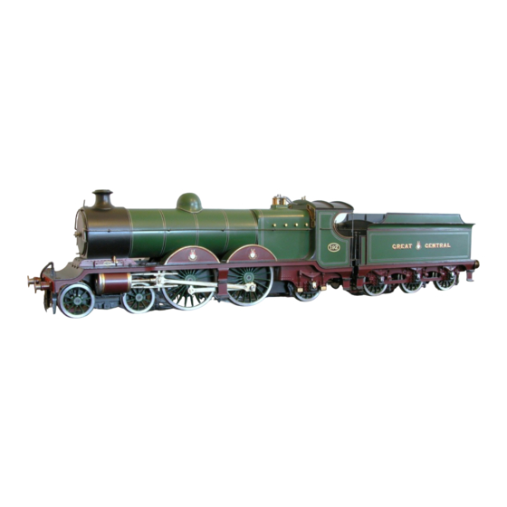
Robinson GCR Class 8B Atlantic
The picture above is for illustration only, it is actually a 7 mm model painted and finished by a very well known artist, whose
writings on the subject are well worth reading. Also worthy of note is the newly released book by John Quick, "Robinson's
Locomotive Liveries on the Great Central Railway".
Page 1 GCR Class 8B
(LNER C4)
Version 1.2 February 2013
Assembly Instructions Revised July 2014
Catalogue #GCM005
This kit is optimised for P4 and EM standards. The kit was designed by "Great Central Models" as part of an
expanding range of Great Central Railway locomotives.
Great Central Models Ltd is registered as a Private Limited Company - 7355519
Enquiries to sales@greatcentralmodels.co.uk or via the contacts page on the web site
Further details - www.greatcentralmodels.co.uk
Advertisement
Table of Contents

Summary of Contents for Great Central Models Robinson GCR Class 8B Atlantic LNER C4
- Page 1 Also worthy of note is the newly released book by John Quick, “Robinson’s Locomotive Liveries on the Great Central Railway”. This kit is optimised for P4 and EM standards. The kit was designed by “Great Central Models” as part of an expanding range of Great Central Railway locomotives.
- Page 2 Page 2 GCR Class 8B Robinson GCR Class 8B LNER C4 The Class 8B was a trial build of a 4-4-2 soon after Robinson decided on a big engine policy. While impressed by the work done by Churchward at Swindon, he seems to have adopted a cautious approach so decided to build 4 locomotives, essentially with all the major features the same, but the Class 8C as a 4-6-0 and the Class 8B as a 4-4-2 Atlantic.
-
Page 3: Additional Notes
Page 3 GCR Class 8B Additional Notes LNER Numbering - there were huge variations in how LNER numbering was applied. Sizes varied, location carried, style varied, sometimes just ‘NE’, sometimes still with the GCR cab side plate and the letter ‘c’ added to the LNER number, sometimes on the tender but mainly on the cab once the LNER got themselves sorted out. -
Page 4: Things To Note
Page 4 GCR Class 8B Ÿ Detailed step-by-step instructions with the drawings extracted from the CAD originals The original CAD drawings were prepared from GA drawings obtained from MOSI in Manchester and scaled at 12” to 1’. During the design process a number of compromises had to be made (such as the frame widths) because of the materials and parts available to the modeller and the P4 and EM standards. - Page 5 Page 5 GCR Class 8B The part numbers and descriptions (where space permits) are half etched on the frets as near to the parts as sensible and match the description that appears in the Parts List. These annotations will appear in the form “212”, or “223,224” or 213-217” or 218- 225+3”.
-
Page 6: Health And Safety
Page 6 GCR Class 8B Soldering I use ‘Nealetin’, a liquid solder with its own flux. This allows very close control of the initial solder join. Most initial joints will be secure using this (or a similar liquid solder). Motion parts should be soldered with a higher temperature solder. Once you are convinced things are square then it is possible to run a small fillet of solder along critical joins by first priming with a little ‘Nealetin’. - Page 7 Page 7 GCR Class 8B There are three wheel sets available, from Alan Gibson, Ultrascale and Exactoscale. For P4, the Alan Gibson wheels have a rear boss which is 0.5 mm deep. This will impact side play, especially for P4 modellers and less so for EM modellers. This rear boss should be removed from Alan Gibson wheels.
- Page 8 Page 8 GCR Class 8B Brakes Locomotive Chassis 55. Brake Frame Mount - Sheet 1 0.015’ 0.375 mm Nickel Silver 56. Brake Frame Mount - Sheet 1 57. Brake Frame Mount - Sheet 1 58. Brake Frame Mount - Sheet 1 Locomotive Frame 59.
-
Page 9: Connecting Rods
Page 9 GCR Class 8B 113. Coupling Rod Right Boss Front - Sheet 2 168. Bogie Spring Hanger - Sheet 1 114. Coupling Rod Right Boss Front - Sheet 2 169. Bogie Spring Hanger - Sheet 1 115. Coupling Rod Right Boss Front - Sheet 2 170. - Page 10 Page 10 GCR Class 8B 226. Valve Rod End - Sheet 2 20. Drwg. 261 MarkitsRAXFBsq601 axle boxes (4 227. Valve Rod End - Sheet 2 supplied) 21. Drwg. 262 GC Smoke Box Handle Markits Spares M4SBDH4 228. Alternative Cylinder Cover Left Board 1 229.
- Page 11 Page 11 GCR Class 8B 52. Fire Box Brace - Sheet 5 Locomotive Body 53. Fire Box Brace - Sheet 5 54. Fire Box Brace - Sheet 5 0.012’ 0.3 mm Brass Boiler 55. Cab Side Left - Sheet 5 1.
-
Page 12: Recommended Tool
Page 12 GCR Class 8B 105. Cylinder Cover Right - Sheet 4 Additional Parts Required - not part of the kit Wheels, motors and gears are a personal choice - these were Springs the ones used by the designer 106. Axle Box Spring Mount - Sheet 4 107. - Page 13 Page 13 GCR Class 8B Main Frame Preparation 1. Frame Layout Note You may wish to leave the main frames in the fret while preparing them. I have found this a lot easier and only remove the frames from the fret when I am ready to join the frames together Note There seems to be a little photographic evidence that when first...
- Page 14 Page 14 GCR Class 8B Remove Rear Wheel Spring Mount Locators (238,239) from the fret, fold with the etch on the outside and locate in place on the 3. Main Frame Spacers insides of the frames. Fire Box Note The firebox is inset from the sides of the frames as on the prototype.
- Page 15 Page 15 GCR Class 8B Connecting the frames together Note P4 Only The frames have a half etch bend close to the front. Now is the time to very carefully bend this inwards (it is only 2 degrees), Use a pair of flat nosed pliers to hold the frames so that the elongated hole for the cylinder spacers is covered and will be held flat. The smoke box base is etched to allow for this bend.
- Page 16 Page 16 GCR Class 8B Caveat 5.Cylinders and Slide Bars It will look nice if you fit the buffers next but it will be wrong because it may inhibit the ease with which the parts of the Cylinder Spacers (7,8) cylinders can be fitted such as when holes need to be reamed out slightly etc Cylinders...
- Page 17 Page 17 GCR Class 8B 6. Slide Bar Measurements Complete the other slide bar parts as above and file to correct profile. They should be 1 mm wide and at the deepest point 1.2 Insert a pair of slide bars into each side of the frames and check they locate correctly and not too tightly into the cylinder head rectangular slots with a small protrusion at the front.
- Page 18 Page 18 GCR Class 8B File down the top and bottom carefully so that they do not hit 8. Coupling Rods the Slide Bar Supports (22,23) and can move freely along the length of the slide bars. Coupling Rods Coupling Rod Left (105) Note The coupling rods are a mirror pair - so take care that all the oil boxes end up at the top!
- Page 19 Page 19 GCR Class 8B There is no reason why the buffer layers should not be made part 10. Rear Buffer A (from rear) of the foot plate and soldered to the ends of the footplate using the rear and front foot plates and the valences as a guide, which Rear Buffer Beam (5) may make fitting body and chassis together a little easier.
- Page 20 Page 20 GCR Class 8B Solder the buffers to Buffer Mounts (32,33) then drill through Foot Plate Fixing 0.45 mm from the rear for the corner fixing bolts. Bracket (38) Remove Foot Plate Fixing Bracket (38) from the fret and fit 13.
- Page 21 Page 21 GCR Class 8B 17.Valve Gear Eccentric Valve Rods Main Eccentric (203,204) Start with the valve gear for the right hand side. Eccentric Short Brackets (209,210) Remove Valve Rod Right Outer (187) and Valve Rod Right Inner (188) from the fret. With a small piece of wet and dry paper ease Eccentric Bracket 205,206) out the large holes to 5.7 mm so that they revolve easily round the brass eccentric plates (Drwg.
- Page 22 Page 22 GCR Class 8B to mark the holes to be drilled. Check that the brass plates will sit 22. Assembly of brass plates in the hole in the template, using a bit of wet & dry to ease as needed.
- Page 23 Page 23 GCR Class 8B 25. Brake Shoe Assembly Brake Shoes Brake Mount (55) Solder Brake Shoe Bases (81-86) to Brake Shoe Top Layer (87- Brake Shoe Base (81) 92) using 0.45 mm brass wire to locate them with respect to each other.
- Page 24 Page 24 GCR Class 8B Drag Link Note The drag link is optional, this is just how it is done on the prototype. The chequered plate between the tender and locomotive may be simply hooked on the front of the tender using a couple of pieces of wire.
- Page 25 Page 25 GCR Class 8B Drill out the 12 holes in Bogie Stretcher (148) to 0.3 mm. These are a set of alternative fittings for the wire that will spring the 32. Bogie Springs And Hangers wheels. Remove Bogie stretcher (148) from the fret, bend to shape and solder in place underneath Bogie Frame (141) so that the Spring Backing Plates (151-156) elongated hole is properly aligned, trying not to block the spring...
-
Page 26: Fitting Wheels
Page 26 GCR Class 8B Add the turned Bogie Pivot (Drwg. 219) to the underside of Bogie Mount (48) on the chassis so that the long part will hang through the bogie when it is fitted. Add thin washers when testing to increase downwards force if needed. Fitting wheels Note This is where a small block of wood will come in handy since soldering the axle boxes and their spring covers on top of it will... - Page 27 Page 27 GCR Class 8B Araldite in place Drwg. 212 Cylinder Front - note that Cylinder Covers (97,98) are supplied with extras and are on the N/S etch and on the brass etch. The cylinder fronts supplied are nickel silver and for early GC days represent the polished and oiled steel fronts.
- Page 28 Page 28 GCR Class 8B 36. Cab Front Body Work Notes Window Overlays (64-67) Cab Front (63) Parts are included for P4 and EM for both these variants. Take care not to get the P4 and EM parts confused. The metal used is 0.3 mm brass. This is delicate, especially so with these style of locomotives where the foot plates are quite narrow.
- Page 29 Page 29 GCR Class 8B distance using locating holes towards the front of the 39. Footplate and Cab footplate. On the foot plates these holes later become the location for oil boxes and sand box fillers. The semi-circular recess in Footplate Assembly Aid (136) will help locate the boiler later on and should be towards the rear.
- Page 30 Page 30 GCR Class 8B lightly solder. This may be removed later once the assembly of 42. Fire Box Arrangement the fire box is finished. If you wish to bulk up the inside of the fire box then remove Fire Box (44) Fire Box Braces (51-54) from the fret and insert into the inside of the fire box using the same 0.45 mm wires to locate securely and accurately - then solder up using lots of heat.
- Page 31 Page 31 GCR Class 8B Rear Foot Plate 45. Rear Footplate Remove Footplate Rear (11) from the fret and fold up the centre section, the tabs of which will act to locate the Cab Floor (89). Frames Ease the slot out that will fit over the chassis frames with a little wet &...
- Page 32 Page 32 GCR Class 8B 48. Cab Arrangement 1 49. Cab Arrangement 2 50. Cab Arrangement 3 51. Roof anneal these first and then bend them. The ones supplied in 2014 are almost correct to size and are 0.8 mm across key dimensions.
- Page 33 Page 33 GCR Class 8B Remove Centre Step Plate Left (90), Centre Step Left Upper 53. Centre Step (91) and Centre Step Left Lower (92) from the fret. Bend Centre Step Plate Left to shape as shown, there is a distinct kink a few inches below the valence to move the steps away from the loading gauge but in reality the displacement is only the thickness of 0.6 mm.
- Page 34 Page 34 GCR Class 8B curve the valences to suit then solder into place against the foot plate support brackets (34-37) with the steps in position temporarily). 56. You are here 1 57. You are here 2 58. You are here 3 Page 34 GCR Class 8B...
- Page 35 Page 35 GCR Class 8B Use Valence Spacing Aids (132-135) to get the position as accurate as possible. Two of these are slightly longer and are used in front of the valence bend but not before the frame 59. Smoke Box Frame bend begins - i.e.
- Page 36 Page 36 GCR Class 8B There is a hole (used later for the snifter) on the Boiler (1) and Smoke Box (5) to help get the alignment correct. The main (visible) boiler should be 60 mm long with about 5 mm inside the smoke box assembly. The circular part of the Smoke Box Frame sits inside Smoke Box and there are two notches to assist in the location.
-
Page 37: Vacuum Pipe
Page 37 GCR Class 8B Hand Rail Bend a length of 0.45 mm brass wire to suit the curve at the front of the smoke box, thread on the Hand Rail Knob for the smoke box and push the two ends through the hand rail knobs on the smoke box and boiler sides and into the holes just under the cab front windows. - Page 38 Page 38 GCR Class 8B Foot Plate Grab Handles If the centre steps are fitted then there should be a grab handle on the footplate. Clear the holes in the foot plates between the leading and centre splashers to 0.45 mm and fit a short length of 0.45 mm brass wire setting it to 0.9 mm above the foot plate. Reversing Arm Note The reversing arm consists of several very fine pieces which are connected using 0.3 mm brass wire through holes in the etch.
- Page 39 Page 39 GCR Class 8B on the chassis sandbox thus preventing a proper fit (in my test case it bent the footplate!). Add Oil Filler Caps (38-43) to the top with the hinge (flat) to the front of the locomotive if these are required (hardly noticeable).
- Page 40 Page 40 GCR Class 8B Page 40 GCR Class 8B...
- Page 41 Page 41 GCR Class 8B Page 41 GCR Class 8B...
- Page 42 Page 42 GCR Class 8B Left Frame inside rear view Spring Wire Left Frame 238, 239 Rear Wheel Spring Mount Locators on NiSi Sheet 2 Also 130,131 on brass Sheet 5 110,111 Rear Wheel Spring Mounts Fold 238, 239 Wheel Spring Mount Locators on NiSi Sheet 2 with the half etch on the outside so that it folds back against itself (also 130,131 on brass Sheet 5 which will give a tighter fit).
Need help?
Do you have a question about the Robinson GCR Class 8B Atlantic LNER C4 and is the answer not in the manual?
Questions and answers