
Summary of Contents for Televes 769501
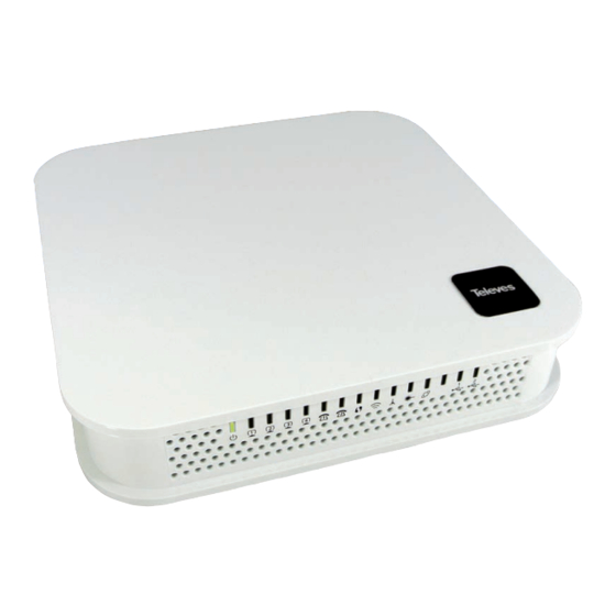
- Page 1 Ref. 769501 Ref. 769502 User´s Manual GPON ONT OFFICE GPON ONT HOME w w w . t e l e v e s . c o m...
-
Page 3: Table Of Contents
Índice Summary ........................................Technical Description ................................... Refs. 769501-769502 Gateway Main Functionalities ....................... Application Scenario .................................... Interoperability ....................................... Interfaces ........................................General Features ....................................General Architecture..................................... GPON .......................................... Ethernet ........................................IPTV ..........................................2.10 RF Video Overlay ....................................2.11 Voice ........................................... 2.12 WI-FI .......................................... - Page 4 Before installing Refs. 769501-769502 device ..........................Connections ......................................How to Setup Refs. 769501-769502 ............................... Interface connection .................................... 4.4.1 Optical cable connection ..................................4.4.2 General Overview of Refs. 769501-769502 Connections ......................Configuration ......................................Refs. 769501-769502 activation ................................ Customization ......................................5.2.1 Software download from the OLT ..............................
- Page 5 5.6.2 WAN Service/ ......................................5.6.3 LAN ..........................................5.6.4 NAT ..........................................5.6.5 Security ........................................5.6.6 Parental Control ...................................... 5.6.7 Quality of Service ....................................5.6.8 Routing ........................................5.6.9 DNS ..........................................5.6.10 UPnP ........................................... 5.6.11 DNS Proxy ......................................... 5.6.12 Storage Service ....................................... 5.6.13 Interface Grouping ....................................
- Page 6 GPON ONT 5.10.7 Update Software ....................................5.10.8 Reboot ........................................5.11 Logout ........................................Operation Indicators ..................................... Refs. 769501-769502 ................................... 6.1.1 LED Indicators Status .................................... 6.1.2 Troubleshooting ..................................... CLI ..........................................Overview ........................................Nodes and Commands ..................................7.2.1 “wan” node ....................................... 7.2.2 “lan” node ........................................
- Page 7 Glossary of Acronyms and Definitions Acronyms and abbreviations Third generation mobile telecommunications Authentication, Authorization, and Accounting Alternating Current Access Concentrator Access Control List Auto Configuration Server Advanced Encryption Standard Address Resolution Protocol Autonomous System AUTO-MDIX Medium Dependent Interface Crossover Automatic Choice Broadband Forum Border Gateway Protocol CAT5E...
- Page 8 GPON ONT IPTV Internet Protocol Television IPv4 Internet Protocol version 4 IPv6 Internet Protocol version 6 Internet Service Provider ITU-T Telecommunications International Telecommunication Union OSI Layer 2 OSI Layer 3 Local Area Network Light Emitting Diode Media Access Control Metropolitan Area Network Mobile Application Part Managed Entity MEGACO...
- Page 9 SSID Service Set IDentifier Set Top Box Software T-CONT Transmission Container Transmission Control Protocol Time Division Multiplexing TDMA Time Division Multiple Access TKIP Temporal Key Integrity Protocol TR-069 Technical Report 069 Time to Live Television User Datagram Protocol Uniform Resource Locator Universal Serial Bus Unshielded Twisted Pair Voice Activity Detection...
-
Page 10: Summary
These base functionalities, together with the support for bit rates of up to 2.5 Gbps (downstream) and 1.24 Gbps (upstream), an optical network splitting ratio of up to 1:64 in a single fiber and a distance range of up to 60 km, make the GPON technology and the Refs. 769501-769502 the most efficient option for passive optical network topologies, when integrated service delivery is an issue. -
Page 11: Technical Description
2. Technical Description 2.1 Refs. 769501-769502 Gateway Main Functionalities The Refs. 769501-769502 Gateway is aimed for customer premises and complies with the ITU-T G.984.x recommendation in order to transport (over GPON) and deliver (to premises domain) the full broadband service pack. -
Page 12: Interoperability
GPON ONT 2.3 Interoperability The ONT gateway family equipment complies with ITU-T G.984.x. Recommendation as like as G.984.4 (OMCI) ensuring multi-vendor OLT interop- erabily with major GPON OLT vendors, as defined in BBF.247 ONU certification program. BBF.247 ONU certification program certifies ONT link layer configuration and management protocol, OMCI, Figure 2-2, as defined by ITU-T G.984.3, ITU-T G.984.4 and ITU-T G.988. -
Page 13: Interfaces
Subscriber Service Network Topology OLT/ONT Management (TL1, SNMP) TR069 OMCI Figure 2-4: IP Based services-TR069 configuration 2.4 Interfaces Client interface options are of type: 4x 100/1000Base-T for Ethernet network connection (RJ45 connectors); 2x FXS channels (RJ11 connectors); 2x2 @ 2.4/5.0 GHz wireless interfaces (802.11 b/g/n); 2x USB 2.0 Masters for printer sharing, media sharing and for 3G/4G backup uplink;... - Page 14 Figure 2-5: Optical fiber Internet service user access In the upstream direction, the Refs. 769501-769502 is connected to the optical splitter and respectively to the OLT through the PON port to pro- vide integrated access services through the service headend.
- Page 15 ETHERNET TDM/TDMA Figure 2-6: Stack of protocols for GPON architecture Several transmission containers (T-CONT) are assigned to each user. Each T-CONT has an associated GEM port and each GEM port has a VLAN identifier and an 802.1p priority level. The ONT classifies the traffic depending on the VLAN and the marked priority, and routes it over the corresponding T-CONT/GEM port. Thus for frame multiplexing, GEM and T-CONT ports are used for uplink while the downlink only use the GEM ports feature.
-
Page 16: General Architecture
Broadcast video signal travels over fiber from the central office in the 1550nm wavelength and is demuxed and converted in the Refs. 769501- 769502 to a F conector (75 Ohm) RF Overlay interface to deliver a RF TV signal going from 47MHz up to 862MHz bandwidth. Refs. 769501-769502 may also implement multiple analog filtering on the RF Interface in order to turn the open RF Spectrum in a group of sliced TV channel packs that are remotely enabled from the NMS. -
Page 17: Voice
Logical interface (VLAN encapsulation) If the Refs. 769501-769502 has no FXS ports and the VoIP service is transparently forwarded from the OLT up to the Home Gateway (and vice versa) within a previously defined voice VLAN. Refs. 769501-769502 respects the defined priority and implements the traffic encapsulation from its own Ethernet interface into a specific T-CONT/GEM-Port over the PON interface and up to the OLT equipment. -
Page 18: Block Diagram
2.12.2 Block Diagram The Refs. 769501-769502 circuit block diagram is presented in the figure bellow showing all oscillators in the device and its frequencies, Figure 9. Intentional radiators in the circuit and radio signal path between circuit blocks are also shown. -
Page 19: Refs. 769501-769502 Wi-Fi Antennas
2.13 Multiple QoS per VLAN The Refs. 769501-769502 supports 802.1p QoS per VLAN services in which several flows (one per allowed pbit) are embedded in the same VLAN. According to the applied configuration, the Refs. 769501-769502 performs a per-flow QoS policy: dropping traffic marked with not allowed pbits and limiting to the configured value the data rate of the allowed flows. -
Page 20: Dynamic Bandwidth Allocation (Dba)
GPON ONT Figure 2-11: Upstream QoS Diagram 2.14.3 Dynamic Bandwidth Allocation (DBA) The DBA (Dynamic Bandwidth Allocation) is available in order to optimize the upstream bandwidth. This mechanism consists in defining an ad- equate T-CONT to the service traffic in question. There are five types of T-CONT, defined by the Fixed, Assured and Maximum Parameters: Type 1: Only fixed Bandwidth;... -
Page 21: Upstream Qos Scenarios
Figure 2-12: Traffic distribution by service/client 2.14.4 Upstream QoS scenarios 8 priority queues Strict-priority Upstream Scheduling: Strict Priority (currently supported) Strict Priority + rate controller (currently supported) Strict Priority + WFQ (can be SW supported) -
Page 22: General Specifications
GPON ONT 3. General Specifications 3.1 Interfaces 3.1.1 GPON The Refs. 769501-769502 GPON G.984.x layer uses 1490nm downstream and 1310nm upstream optical wavelengths, with 2,488Gbps downstream and 1,244Gbps upstream by using an SC/APC protected optical connector. 3.1.1.1 Optical interfaces Items... -
Page 23: Ethernet
3.1.3 RF Overlay Broadcast video signal travels over fiber from the CO in the 1550nm wavelength and is demuxed and converted in the Refs. 769501-769502 to a F connector (75 Ohm) RF Overlay interface to deliver a RF TV signal going from 47MHz up to 1GHz of bndwidt. -
Page 24: Fxs
769502 FXS interface specifications table values are configurable at the web management interface at the menu Voice, item SIP basic settings, by selecting the local(Country) where the Refs. 769501-769502 will be used. Please refer to section SIP BASIC SETTING, for details on this configuration. -
Page 25: Wi-Fi
3.1.5 WI-FI Items Compliance Description IEEE 802.11 b/g/n Bit Rates 802.11 b/g 1, 2, 5.5, 6, 9, 11, 12, 18, 24, 36, 48 and 54Mb/s 802.11 n Up to 300Mb/s over two spatial streams SSID Up to 8 Operation Fre- 2.4GHz (ISM) or 5GHz (U-NII) quencies Channels... -
Page 26: General Features
NOTES: (1) Optional ; Dependent on the Refs. 769501-769502 specific model (2) An LPS power source is used to power the ONT equipment: US/Canada: The ONT must be powered by an external Listed Limited Power Source (LPS) or Class 2 Power source. The external power adapt- er must be LPS certified. -
Page 27: General Service Description
3.3 General Service Description GPON layer per > Comply with GPON standard: ITU-T G984.1/ > Class B+ optics (28 dB); G984.x G984.2/G984.3/G984.4; > T-CONT:32; > GPON Encapsulation Method (GEM) supports > GEM-Port-IDs: 32. Ethernet; > Configurable AES Downstream and FEC Down- stream and Upstream;... -
Page 28: Optical Metering
The equipment measures the downstream received power from the OLT in 1490nm and reports this value through OMCI. The accuracy of the measurement is +/- 3dBm, maximum. Optionally, Refs. 769501-769502 has also the chance to have an embeded optical reflective component in order to increase the FTTH probing capabilities in a 50 centimeters resolution factor, which turns to have a single probing system to probe all GPON network ONTs even when its number increases over Million customers. -
Page 29: Gpon Management
Firmware upgrade through the PON interface following the mechanisms specified in the ITU-T G.984.4 and G.988, including a safe dual firmware updates image system and the ability of back-up, allowing the SINGLE PORT Refs. 769501-769502 start in case the software download fails, to enable a new software update. -
Page 30: Standards
GPON ONT 3.8 Standards EMC Directive 89/336/EEC, EMC Addendum Directive 92/31/EEC, EMC Addemdum Directive 91/263/ Standards (Telecommunications Terminal Equipment Directive) Emissions EN50081-1, EN55022 EN50082-1, EN61000-4-2, EN61000-4-3, Immunity EN61000-4-4 Temperature EN300019 Operating Limits Relative humidity, maximum EN300019 Environmental Standards Acoustic noise ISO 3743 (<45dBa) Power and Grounding ETSI EN 300 132-2 V2.1.1 (2003-01) -
Page 31: Setup
Never assume that the laser beam is inactive or that the optical fibre is switched off. 4.2 Connections Refs. 769501-769502 connections are distributed by two side faces of the device Refs. 769501-769502 connections’ general view is show in the following picture, Figure 4-1. - Page 32 If not pressed only POWER and RADIO SIGNAL LEDs have up- dated status information. WPS - WI-FI Protected Set-up 12V DC Power Supply Connector Table 4-1: Refs. 769501-769502 connections description NOTES: (1) Optional ; Dependent on the Refs. 769501-769502 specific model...
-
Page 33: How To Setup Refs. 769501-769502
The Refs. 769501-769502 may be installed horizontally on a flat surface or wall mounted. Quick steps for these setups are described below. Wall-mount Refs. 769501-769502 wall mounting kit consists of two AGL. ZN. CC. PZ. 3,5X30mm screws, standard DIN 7505-B and two Nylon M 6X30 wall an- chors. - Page 34 Pass the other end of the optical patchcord to the outside of the equipment using the passing hole, Figure 4-4- f ); Fix the optical patchcord with plastic clamps to the Refs. 769501-769502 the appropriate fixing support fastening the plastic clamp...
-
Page 35: Interface Connection
4.4.2 General Overview of Refs. 769501-769502 Connections Figure 4-6 below shows the connections to be made between the Refs. 769501-769502 and the home network devices. Please refer to Figure 4-1 and 4-1 for the Refs. 769501-769502 connector description and to Table 4-2 for the description of the connecting cables that must be used. - Page 36 Ethernet Cable UTP CAT56 cable (direct or crossover) Single-mode Optical Cable with SC/APC Connector (GPON) C5 (1) Cable with F-type Connectors, Coaxial 75 Ohm WI-FI NOTES: (1) Optional ; Dependent on the Refs. 769501-769502 specific model Table 4-2: Refs. 769501-769502 connections...
-
Page 37: Configuration
Active - if it is loaded and it is being executed in the Refs. 769501-769502. There can be only one active image and only one commited image at a given moment. The Refs. 769501-769502 goes through a series of states in order to download and activate a software image. -
Page 38: Network Setup
GPON ONT 5.3 Network Setup Refs. 769501-769502 is the link between the modem and all of the peripherals in the LAN. The following figure shows a possible network setup containing three wireless computers and two wired computers. Figure 5-1: Refs. -
Page 39: Device Info
Figure 5-3: Refs. 769501-769502 management main screen The Refs. 769501-769502 Management lets the user configure these categories by clicking the folder icons in the Control Menu pane. Device Info Advanced Setup Wireless Voice Diagnostics Management 5.5 Device Info Selecting Device Info menu item, expands Device Info sub-menu into listed items, Figure 5-4:... -
Page 40: Summary
GPON ONT Figure 5-4 : Refs. 769501-769502 Graphic User Interface main menu 5.5.1 Summary Selection of Device Info sub-menu item Summary, displays in the main window the initial device info configuration details, Figure 5-5. The initial displayed information will be updated to the current device info details by the performed configuration settings of the ONT. Description of the Device Info window parameters can be found in Table 5-1 Figure 5-5: Device Info details –... -
Page 41: Wan
5.5.2 WAN Selection of the Device Info sub-menu item WAN displays in the main window the current WAN configuration details, Figure 5-6. The window is composed of two tables: WAN info; GRE Tunnels Status Description of the WAN Info Table parameters can be found in Table 5-2 and GRE Tunnels Status table parameters in.Table 5-3. Figure 5-6: WAN current configuration details window –... -
Page 42: Statistics
GPON ONT Parameter Description Gre Tunnel identification (string) configured when gre Tunnel Name tunnel is created Local IP IP address of the local end interface of the GRE tunnel Remote IP IP address of the local end interface of the GRE tunnel Tunnel IP Tunnel IP Address Peer IP... - Page 43 Parameter Description LAN interface Identification (string). eth #, # - number : 0 to 3 – Refs. 769501-769502 Interface ETH port number wl0, Wireless interface Total values (Multicast+Unicast+Broadcast) of: Bytes – Total number of Received /Transmitted Bytes Total Pkts – Total number of Received/transmitted...
- Page 44 GPON ONT 5.5.3.2 WAN Service Selection of the Device Info, Statistics sub-menu Item WAN service displays in the main window the Wide Area Network statistics information per configured Wan service, Figure 2-1. WAN Service statistics parameter description can be found in Table 5-2. Figure 5-9: WAN Statistics Parameter Description...
-
Page 45: Route
Selection of the Device Info sub-menu Route item, compresses the open Device info sub-menu if expanded (eg Statistics) and shows in the main window the Device Routing information, Figure 5-10. In the example bellow the destination address is the address of the Refs. 769501-769502 bridge (br0 Interface) and the route status is up. -
Page 46: Arp
ARP is used to convert an IP address to a Physical address. The ARP table In the example bellow the IP Address is the allocated IP address by the Refs. 769501-769502 the latop connected to one of the device ETH LAN ports and used to access the device GUI (Graphic User Interface) for Device configuration. -
Page 47: Voice
Hostname lease by the Refs. 769501-769502) Name External Device (with an IP Address was attributed by MAC Address DHCP lease by the Refs. 769501-769502) MAC Address External Device IP Address attributed by DHCP lease by the IP Address Refs. 769501-769502... -
Page 48: Advanced Setup
5.6.1 Layer2 Interface This menu item allows the configuration of the wan ONT-wan interface (uplink interface) as GPON wan interface or ETH wan interface (physical e Refs. 769501-769502 is electrical ETH interface). In the last case th configured simply as a conventional RGW. -
Page 49: Wan Service
Figure 5-15: GPON WAN Interface Configuration- initial window Parameter Description Refs. 769501-769502 WAN interface Identification. In the case of GPON Wan interface Interface/(Name) – veip0/veip0 Connection Mode Value: VlanMuxMode Remove If selected, the WAN interface can be removed with Remove button Table 5-10: GPON WAN interface configuration Table parameters 5.6.2 WAN Service... - Page 50 To create a WAN service, use the ADD button in the Advanced Setup WAN service Main window, Figure 5-20. A new window will be displayed Refs. 769501-769502 WAN interface associated to the service to create, Figure 5-21. Once where is possible to select on a combo box the selected the WAN interface use the Next Button, Figure 5-22, to progress t o the next WAN service configuration window –...
- Page 51 Four types of WAN services can be created and configured: PPP over Ethernet (PPPoE) IP over Ethernet (IPoE) GRE Tunneling (over Layer 2) Bridging. Figure 5-22: WAN service Interface selection for the WAN service to setup 5.6.2.1.1 PPPoE Type of Service Creation After the selection of the WAN interface associated to the service to create, Figure 5-21 and Figure 5-22, use the Next button Figure 5-22, to prog- ress to the next WAN Service setup window- Wan service Configuration, Figure 5-23 At this window execute the following steps:...
- Page 52 GPON ONT 5.6.2.1.2 VLAN Tagging Configuration Procedure STEP 3. For tagged service, at the field 802.1P priority, enter the pbit value (0-7) to mark the upstream traffic according to the desired CoS for the service to create; a higher value corresponds to a higher priority CoS; For untagged service leave the filed with the default value of -1;...
- Page 53 Figure 5-26: WAN service setup– type of service selection and service configuration – finalize type of service configuration...
- Page 54 GPON ONT The WAN Service Setup window– Connection establishment configuration, Figure 5-27, allows the configuration of the PPoE connection establish- ment parameters, as explained bellow. Figure 5-27: WAN Service Setup – Connection establishment configuration window...
- Page 55 5.6.2.1.3 PPPoE Connection Establishment Parameters Configuration STEP 1. Select the PPP username and password and use the access data provided by your ISP Username and password) to establish the PPPoE connection, Figure 5-27; STEP 2. At the authentication method selection combo box select one of the available option, Figure 5-28: AUTO;...
- Page 56 GPON ONT Figure 5-29:WAN Service Setup – Connection establishment configuration window- Enable fullcone NAT warning message Figure 5-30:WAN Service Setup – Connection establishment configuration window- Dial on demand Configuration Figure 5-31:WAN Service Setup – Connection establishment configuration window- Use of static IPv4 Configuration Figure 5-32: WAN Service Setup –...
- Page 57 Figure 5-33: WAN Service setup - Routing Default Gateway configuration window After default gateway interface configuration, use the Next button, Figure 5-33, to progress to the next WAN Service setup – DNS Server configu- ration parameters window, Figure 5-34. 5.6.2.1.5 DNS Server Configuration DNS server interface can either be selected from available WAN interfaces, Figure 5-34, 1, from the list Selected DNS Server Interfaces, according to its priority (please see description bellow),...
- Page 58 GPON ONT Available WAN Interfaces: all defined available routed WAN interfaces are listed here; these interfaces can be moved to the Selected DNS Server interfaces list If there is only one WAN interface defined in the system, as in the example presented, this will be selected by the system as the default gateway interface thus being presented is the Selected DNS Server list on the left.´...
- Page 59 To finalize the configuration use the Save/Apply button, Figure 5-35. The next displayed window is initial window, the WAN Service Window, where the service configured is displayed in the corresponding table, Figure 5-36. Figure 5-36: WAN Service Setup Initial Window- service configuration displayed It is now possible to view the configured WAN service parameters as well as obtained IP address by Selecting the Device Info sub-menu item WAN, Figure 5-37.
- Page 60 GPON ONT Figure 5-39: Advanced Setup / routing - current routing table...
- Page 61 Figure 5-40: Advanced Setup / DNS- current DNS server table...
- Page 62 GPON ONT Figure 5-41: Advanced Setup /Interface Grouping- current Interface Grouping table 5.6.2.2 IPoE Type of Service Creation After the selection of the WAN interface associated to the service to create, Figure 5-21 and Figure 5-22 , use the Next button at Figure 5-22, to progress to the next WAN Service setup window- Wan service Configuration, Figure 5-42.
- Page 63 Figure 5-42: WAN service setup-type of service selection and service configuration – IPoE service 5.6.2.2.1 WAN IP Settings WAN IP Settings should use the information provided by the ISP. IP address can be obtained automatically via DHCP or can be statically configured. 5.6.2.2.1.1 Obtain IP Address Automatically STEP 1.
- Page 64 GPON ONT 5.6.2.2.1.2 Use of Static IP Address STEP 1. Select the option “Use the following Static IP address “, option 2 of Figure 5-43. STEP 2. Enter WAN IP address to be used Enter WAN Subnet Mask to be used; Enter WAN gateway IP Address to be used STEP 3.
- Page 65 Figure 5-44: WAN Service setup window- NAT, IGMP and Arping Settings configuration Figure 5-45: WAN Service setup window- Network Address Translation Settings configuration Enable fullcone NAT warning message Figure 5-46: WAN Service setup window- IGMP Multicast configuration options Figure 5-47: WAN Service setup window- ArPing Setup...
- Page 66 GPON ONT Once the NAT, IGMP and Arping Settings are configured use Next button Figure 5-44, to progress to the next WAN Service setup - Routing Default Gateway configuration window, Figure 5-48. The actual default gateway configuration is presented in this window, with the ppp0.1 WAN interface previously configured shown as the default Gateway interface.
- Page 67 Figure 5-49: WAN Service setup – DNS Server configuration parameters window Once the DNS server configuration is done the IPoE WAN service configuration is complete. Use the Next button to progress to the WAN Service Setup Summary window, Figure 5-50. This table should reflect the configuration for the WAN service setup parameters than have been entered on the successive WAN service setup configuration windows.
- Page 68 Figure 5-52: Device Info-WAN Service Current configuration and IP Addresses 5.6.2.3 GRE Type of Service Creation A GRE tunnel configuration example will be given, showing the GRE tunnel settings configuration at the Network A Refs. 769501-769502. Network A Network B...
- Page 69 After the selection of the WAN interface associated to the service to create, Figure 5-21 and Figure 5-22, use the Next button at Figure 5-22, to progress to the next WAN Service setup window- Wan service Configuration, Figure 5-54. At this window execute the following steps: STEP 1.
- Page 70 In the basic configuration mode only Tunnel Name and Remote IP are required for setting the GRE Tunnel, Figure 5-56. Remote IP is the Public IP address of the routing device terminating the GRE Tunnel in the other extreme of the tunnel (Refs. 769501-769502 of network B in the shown example), Figure 5-53.
- Page 71 Figure 5-58: WAN Service Setup Initial Window- service configuration displayed It is now possible to view the currently configured WAN services’ parameters as well as obtained IP addresses by Selecting the Device Info sub- menu item WAN, Figure 5-59. Figure 5-59: Device Info- WAN service Current configuration 5.6.2.3.2 GRE Tunnel Setting –...
- Page 72 769501-769502 of network A in the shown example), Figure 5-53. Public IP address of the routing device terminating the GRE Tunnel in the other ex- Remote IP treme of the tunnel (Refs. 769501-769502 of network B in the shown example), Fig- ure 5-53. Tunnel Name GRE Tunnel Identification (string) IP address of GRE Tunnel interface, on the routing device being configured (Refs.
- Page 73 It is now possible to view the currently configured WAN services’ parameters as well as obtained IP addresses by Selecting the Device Info sub- menu item WAN, Figure 5-63. Figure 5-63:Device Info- WAN Service Current configuration 5.6.2.3.3 Interface Grouping for GRE After the GRE tunnel creation, association between the WAN and the desired interfaces must be done.
- Page 74 GPON ONT Figure 5-64: Advanced Setup- interface grouping configuration window Figure 5-65: Wan interface used in the grouping selection combo box...
- Page 75 Figure 5-66: Advanced Setup- interface grouping configuration window Figure 5-67: Advanced Setup- Interface grouping configuration initial Window: Current interface grouping configuration...
- Page 76 GPON ONT 5.6.2.4 Bridging Service Configuration After the selection of the WAN interface associated to the service to create, Figure 5-21 and Figure 5-22 , use the Next button at Figure 5-22, to progress to the next WAN Service setup window- Wan service Configuration, figure 5-68. Figure 5-68: WAN service setup –...
- Page 77 0x8100, TPID default value; if selected a single tagged service is configured 0x88A8 or 0x9100, TPID used for the outer VLAN (S-VLAN) for double tagged services; if selected a double VLAN tagged service is configured; in this case the inner VLAN (C-VLAN) tag TPID has the default value of 0x8100; STEP 7.
-
Page 78: Lan
GPON ONT Figure 5-71: Device Info- WAN Service Current configuration and IP Address Service statistics can be obtained by selecting at the menu Device Info the submenu Statistics, item Wan; a Services-WAN statistics window will be displayed, Figure 5-72. Please refer to Table 5-5 for the description of the statistics window displayer parameters. Figure 5-72: Device Info/Statistics/WAN-- WAN Services Statistics Information 5.6.3 LAN Selection of Advanced Setup submenu item LAN will display a LAN submenu with two items, Figure 5-73:... - Page 79 Figure 5-74: Advanced Setup - LAN Setup window At this window execute the following steps: STEP 1. IP Address –This is the Refs. 769501-769502 IP Address, default value 192.168.1.1, Figure 5-74-1; STEP 2. Refs. 769501-769502 sub network Mask ; default value is 255.255.255.0, Figure 5-74-2;...
- Page 80 Static IP lease settings allow the reservation of static IPs for PCs in the LAN that will therefore obtain the same static IP address each time they request an IP address from the Refs. 769501-769502 DHCP server . For the Refs. 769501-769502 DHCP Server up to 32 Static IP leases can be configured STEP 10.
- Page 81 Figure 5-75: Advanced Setup - LAN Setup window- Enable Secondary server (for DHCP Option 60) STEP 12. To finalize the configuration use the Save/Apply button, Figure 5-74, -12; the displayed window will show the LAN settings cur- rent configuration 5.6.3.1 LAN VLAN Settings Selection of Advanced Setup submenu LAN, item will Lan VLAN Setting a Local Area Network (LAN) VLAN Setup window is displayed in the main window Figure 5-74.
- Page 82 GPON ONT Figure 5-77: Advanced Setup –LAN/ Lan VLAN setup window- Add and configure a Lan VLAN Lan VLAN can be configured in advance as described before and not enabled. To Enable Lan VLAN afterwards, option “Enable VLAN Mode” must be selected, and then the Save/Apply button used to finalize the configuration.
- Page 83 Figure 5-78: Advanced Setup –LAN/ IPv6 VLAN Auto Configuration window...
-
Page 84: Nat
GPON ONT 5.6.4 NAT Selection of Advanced Setup submenu item NAT will display a NAT submenu with three items, Figure 5-79: Virtual Servers Port Triggering DMZ Host In the main window a NAT-Virtual Servers Setup window is displayed, Figure 5-80, showing the current NAT-Virtual servers configuration. Figure 5-79: Advanced Setup NAT Sub-menu 5.6.4.1 Virtual Servers Selection of Advanced Setup submenu NAT, item Virtual Servers a NAT-Virtual Servers Setup window is displayed in the main window Figure 5-80,... - Page 85 Figure 5-80: Advanced Setup/NAT-Virtual Servers Setup window Figure 5-81: Advanced Setup/NAT-Virtual Servers Setup window - Wan port, Service and Server IP Address Configuration...
- Page 86 GPON ONT Figure 5-82: Advanced Setup/NAT-Virtual Servers Setup window - Service Selection Combo box Figure 5-83: Advanced Setup/NAT-Virtual Servers Setup window - Current NAT Virtual Server Configuration 5.6.4.2 Port Triggering Selection of Advanced Setup submenu NAT, item Port Triggering, a NAT-Port Triggering Setup window is displayed in the main window Figure 5-84, showing the current NAT- Port Triggering configuration.
- Page 87 To apply and save this configuration use the Apply/Save button, bellow Figure 5-85-1. The port triggering table will be updated with the chosen application predefined port Triggering configuration, Figure 5-84. To finalize the configuration use the Apply/Save button below the table, Figure 85-2. The next displayed window is the initial window, showing the current NAT - Port Triggering configuration, Figure 5-86.
- Page 88 GPON ONT Figure 5-86: Advanced Setup/NAT-Port Triggering Setup window -Current configuration 5.6.4.3 DMZ Host Selection of Advanced Setup submenu NAT, item DMZ Host, a NAT-DMZ Host Setup window is displayed in the main window Figure 5-87, allowing the DMZ Host configuration by Providing the DMZ Host IP address. A short on line help text is provided in the setup window. A DMZ Host is a host exposed to the internet.
-
Page 89: Security
5.6.5 Security Selection of Advanced Setup submenu item Security will display a Security submenu with two items, Item IP Filtering is a submenu composed of two items, Outgoing and Incoming, Figure 5-88: IP Filtering, Outgoing Incoming MAC Filtering In the main window an Outgoing IP Filtering Setup window is displayed, Figure 5-89. This window allows the creation and configuration a filter rule to identify outgoing IP traffic. - Page 90 GPON ONT STEP 5. Enter the Source Port; STEP 6. Enter the Destination IP address; STEP 7. Enter the Destination Port; To finalize the configuration use the Apply/Save button. The next displayed window is the initial window, showing the current Outgoing IP Filter- ing configuration, Figure 5-91.
- Page 91 5.6.5.1.2 Incoming Selection of Advanced Setup submenu Security, submenu IP Filtering, item Incoming, will display an Incoming IP filtering Setup window, Figure 5-92, showing the current Incoming IP Filtering configuration. A short on line help text is provided in the configuration window. To insert and configure a new Incoming IP Filter entry use the Add Button, Figure 110;...
- Page 92 GPON ONT Figure 5-93: Advanced Setup, Security - Incoming IP filtering Setup – Add Filter window Figure 5-94: Advanced Setup, Security - Incoming IP filtering Setup- Add Filter window – Protocol selection combo box Figure 5-95: Advanced Setup, Security - Incoming IP filtering Setup- Add Filter window - Configuration exemple...
- Page 93 Figure 5-96: Advanced Setup, Security - Incoming IP filtering Setup window – Current Configuration 5.6.5.2 MAC Filtering Selection of Advanced Setup submenu Security, item MAC Filtering displays a MAC filtering Setup window, Figure 5-97, showing the current MAC Filtering configuration: Policy and rules. A short on line help text is provided in the configuration window.
- Page 94 GPON ONT Figure 5-97: Advanced Setup, Security – MAC filtering Setup window Figure 5-98: Advanced Setup, Security – MAC filtering Setup window –Change policy...
- Page 95 Figure 5-99: Advanced Setup, Security – MAC filtering – Add MAC Filter window Figure 5-100: Advanced Setup, Security – MAC filtering Setup window –Current Configuration...
-
Page 96: Parental Control
GPON ONT 5.6.6 Parental Control Selection of Advanced Setup submenu item Parental Control will display a Parental Control submenu with two items, Figure 5-101: Time Restriction, Url Filter In the main window an Access time Restriction Configuration window is displayed, Figure 5-102. This window allows the creation and configuration Access Time Restriction Rules. - Page 97 Figure 5-102: Advanced Setup, Parental Control – Time Restriction Configuration window Figure 5-103: Advanced Setup, Parental Control, Time Restriction -Add Time Restriction rule window Figure 5-104: Advanced Setup, Parental Control – Time Restriction Configuration window - Current configuration...
- Page 98 GPON ONT 5.6.6.2 URL Filter Selection of Advanced Setup submenu Parental Control, item Url Filter will display an URL Filter configuration window showing the current URL Filter configuration table, Figure 5-105. This window allows the creation and configuration of an URL Filter list. A short on line help text is provided in the configuration window Figure 5-105.
-
Page 99: Quality Of Service
QoS Queue, QoS Classification This Submenu allows QoS configuration. It is assumed that the Refs. 769501-769502 has the following services already configured: IPoE with NAT and PPPoE services. In the main window a QoS Queue Management Configuration window will be displayed, Figure 5-109 QoS is disabled by default - it must be enabled by selecting the Enable QoS option, Figure 5-109. - Page 100 GPON ONT Figure 5-110: Advanced Setup Quality of Service- Queue Management Configuration- Select Default DSCP mark combo box 5.6.7.1 QoS Queue Selection of Advanced Setup submenu Quality of Service, item QoS Queue will display a QoS Queue Setup Configuration window, Figure 5-111. This window displays the current QoS configured queues.
- Page 101 Figure 5-111: Advanced Setup Quality of Service- QoS Queue Setup Figure 5-112:Advanced Setup Quality of Service- QoS Queue Configuration Figure 5-113: Advanced Setup Quality of Service- QoS Queue enable example configuration...
- Page 102 GPON ONT Figure 5-114: Advanced Setup Quality of Service- QoS Queue Setup window- current configuration 5.6.7.2 QoS Classification Selection of Advanced Setup submenu Quality of Service, item QoS Classification will display a QoS Classification Setup window Figure 5-115. A short on line help text is provided in the configuration window. To insert and configure a new QoS classification rule use the Add Button, Figure 5-115;...
- Page 103 STEP 11. Specify the Mark Differentiated Service Code (DSCP) STEP 12. Specify the Mark 802.1p Priority To finalize the configuration use the Apply/Save button. The next displayed window is the initial window, showing the current QoS Classification configuration, Figure 5-117. Figure 5-115: Advanced Setup Quality of Service- QoS Classification Setup window Figure 5-116: Advanced Setup Quality of Service- QoS Classification –...
-
Page 104: Routing
GPON ONT Figure 5-118: Advanced Setup Quality of Service- QoS Queue Setup window- current configuration-Queue Enable 5.6.8 Routing Selection of Advanced Setup submenu item Routing will display a Routing submenu with six items, Figure 5-119: Default Gateway, Static Routing, BGP, Policy Routing, RIP/OSFP. - Page 105 5.6.8.1 Default Gateway Selection of Advanced Setup submenu Routing, item Default Gateway will display a Routing-Default Gateway configuration window, Figure 5-120. A short on line help text is provided in the configuration window. The Routing Default Gateway configuration window presents two lists: Selected Default Gateway Interfaces: the WAN interfaces that can be used as default gateway interfaces are listed here;...
- Page 106 GPON ONT 5.6.8.2 Static Routing Selection of Advanced Setup submenu Routing, item Static Routing will display a Routing-Static Route configuration window, Figure 5-121. This window displays the current static routing configuration and allows the insertion/removal of static routes. A short on line help text is provided in the configuration window. To insert and configure a new Static Route use the Add Button, Figure 5-121;...
- Page 107 Figure 5-123: Advanced Setup, Static Routing-Configuration window- Current configuration 5.6.8.3 BGP Selection of Advanced Setup submenu Routing, item BGP will display a Routing-BGP configuration window, Figure 5-124. This window allows the configuration of the: BGP router, Neighbors, Networks. A short on line help text is provided in the configuration window. To be able to configure the BGP router you must have the following information on the router parameters: Autonomous System Number (Number: 0 to 65535) Router ID (Optional) - IP address of one of the router interfaces...
- Page 108 GPON ONT For the configured neighbors a selection box under the Remove column allows the removal of neighbors. In order to remove a neighbor from the table: STEP 1. For the neighbor to remove, select the box under the remove column; STEP 1.
- Page 109 Figure 5-124: Advanced Setup, Routing- BGP Configuration window Figure 5-125: Device Info -Route information window – example of BGP routes announced...
- Page 110 GPON ONT 5.6.8.4 Policy Routing Selection of Advanced Setup submenu Routing, item Policy Routing will display a Policy Routing Setting window, Figure 5-126. This window displays the current Policy routing configuration and allows the insertion/removal of new Policy routing rules. A short on line help text is provided in the configuration window.
- Page 111 Figure 5-128: Advanced Setup, Routing- Policy Routing Setting window- current configuration 5.6.8.5 RIP/OSPF Selection of Advanced Setup submenu Routing, item RIP/OSPF will display a Routing-RIP Configuration window, Figure 5-129. This window allows the configuration of the: OSPF A short on line help text is provided in the configuration window. Figure 5-130 provides a RIP and OSPF configuration example.
- Page 112 GPON ONT For the configured OSPF a selection box under the Remove column allows the removal of OSPF configuration. In order to remove an OSPF configuration from the table: STEP 1. For the OSPF configuration to remove, select the checkbox under the remove column; STEP 2.
-
Page 113: Dns
Figure 5-130: Advanced Setup, Routing- RIP and OSPF Configuration example 5.6.9 DNS Selection of Advanced Setup submenu item DNS will display a DNS submenu with two items, Figure 5-131: DNS Server, Dynamic DNS. In the main window a DNS Server Configuration window will be displayed, Figure 5-132. Figure 5-131: Advanced Setup DNS Sub-menu... - Page 114 GPON ONT 5.6.9.1 DNS Server Selection of Advanced Setup submenu DNS, item DNS Server will display a DNS Server configuration window, Figure 5-132. A short on line help text is provided in the configuration window. The DNS Server configuration window presents two lists: Selected DNS Server Interfaces: the WAN interfaces that can be used as DNS Server interfaces are listed here;...
- Page 115 Figure 5-132: Advanced Setup, DNS Server Configuration Window 5.6.9.2 Dynamic DNS Selection of Advanced Setup submenu DNS, item Dynamic DNS will display a Dynamic DNS configuration window, Figure 5-133. This window displays the current Dynamic DNS configuration. A short on line help text is provided in the configuration window. To insert and configure a new Dynamic DNS entry use the Add Button, Figure 5-133;...
- Page 116 GPON ONT STEP 4. At the DynDNS Settings type in the username; STEP 5. At the DynDNS Settings type in the Password; To finalize the configuration use the Apply/Save button. The next displayed window is the initial window, showing the current Access Dynamic DNS configuration, Figure 5-135.
-
Page 117: Upnp
5.6.10 UPnP Selection of Advanced Setup submenu item UPnP will display a UPnP Configuration window, Figure 5-136. To enable UPnP select the option “Enable UPnP” and use the Apply/Save button to finalize de configuration. Note: UPnP is activated only where there is a live WAN service with NAT enabled. Figure 5-136: Advanced Setup, UPnP Configuration Window 5.6.11 DNS Proxy Selection of Advanced Setup submenu item DNS Proxy will display a DNS proxy Configuration window, Figure 5-137. -
Page 118: Storage Service
GPON ONT 5.6.12 Storage Service Selection of Advanced Setup submenu item Storage Service will show A Storage Device Info submenu item, Figure 5-138 and display a Storage Service Device Information window, Figure 5-139 This window displays information on the current Storage connected to the USB Ports. Figure 5-138:Advanced Setup Storage Service Sub-menu Figure 5-139: Advanced Setup Storage Service configuration window 5.6.13 Interface Grouping... - Page 119 STEP 6. To finalize the configuration use the Save/Apply button, Figure 5-140-6. The next displayed window is initial window, the Advanced Setup- Interface grouping initial window showing the current configuration, Figure 5-142 Figure 5-140: Advanced Setup- interface grouping configuration window- Setup on an Interface grouping example Figure 5-141:Advanced Setup- interface grouping configuration window...
-
Page 120: Ip Tunnel
GPON ONT Figure 5-142: Advanced Setup- Interface grouping configuration initial Window: Current interface grouping configuration 5.6.14 IP Tunnel Selection of Advanced Setup submenu, item IP Tunnel item will display an IP Tunnel submenu with two items, Figure 5-143: IPv6inIPv4, IPv4inIPv6 In the main window an IP Tunneling-6in4 Tunnel Configuration window will be displayed, Figure 5-144. - Page 121 5.6.14.1 IPv6inIPv4 Selectionof Advanced Setup, IP Tunnel submenu, IPv6inIPv4 item, will display an IP Tunneling-6in4 Tunnel Configuration window, Figure 5-144. This window displays the current IP Tunneling-6in4 Tunnel Configuration. To insert and configure a new IPv6 into IPv4 tunnel entry use the Add Button, Figure 5-144; a new window is displayed, Figure 5-145. A short on line help text is provided in the configuration window.
- Page 122 GPON ONT Figure 5-145: Advanced Setup, IP tunnel IP- Tunneling-6in4 Tunnel: Add Tunnel Configuration window Figure 5-146: Advanced Setup, IP tunnel IP- Tunneling-6in4 Tunnel Add Tunnel Configuration window example Figure 5-147: Advanced Setup, IP tunnel IP- Tunneling-6in4 Tunnel Configuration window- current configuration...
- Page 123 5.6.14.2 IPv4inIPv6 Selection of Advanced Setup, IP Tunnel submenu, IPv4inIPv6 item, will display an IP Tunneling-4in6 Tunnel Configuration window, Figure 5-148. This window displays the current IP Tunneling-4in6 Tunnel Configuration. To insert and configure a new IPv4 into IPv6 tunnel entry use the Add Button, Figure 5-148; a new window is displayed, Figure 5-149. A short on line help text is provided in the configuration window.
-
Page 124: Power Management
GPON ONT Figure 5-150: Advanced Setup, IP tunnel IP- Tunneling-4in6 Tunnel Configuration window- current configuration 5.6.15 Power Management Selection of Advanced Setup, Power Management item, will display Power Management control and information window, Figure 5-151. This window allows the control of Hardware modules to evaluate power consumption. Hardware modules can be enabled by selecting the cor- responding checkbox and use the enabled button. - Page 125 STEP 1. Configure Multicast Precedence from the Selection combo box; Options available are: Disable Precedence value (lower value, higher priority) IGMP and MLD configurations are filled with default values, Figure 5-152, that can be modified if desired. In order to proceed with Multicast dafault configuration values just go to the bottom of the window and use the Apply/Save to finalize the configuration.
-
Page 126: Wireless
GPON ONT 5.7 Wireless Selection of Advanced Setup submenu item Wireless will display a Wireless submenu with six items, Figure 5-153: Basic, Security, MAC Filter, Wireless Bridge, Advanced, Station Info. In the main window a Wireless-Basic Configuration window will be displayed, Figure 5-154. Figure 5-153: Wireless submen 5.7.1 Basic Selection of Advanced Setup submenu Wireless, item Basic will display a Wireless-Basic configuration window, Figure 5-154. - Page 127 STEP 9. Type in Country RegRev STEP 10. Type in the maximum number of clients STEP 11. At the wireless-guest/virtual Access Points configuration table use the checkboxes to configure Virtual access points To finalize the configuration use the Apply/Save button at the bottom of the window. Figure 5-154: Wireless -Basic configuration window –configuration exemple...
-
Page 128: Security
GPON ONT 5.7.2 Security Selection of Advanced Setup submenu Wireless, item Security will display a Wireless-Security configuration window, Figure 5-155. A short on line help text is provided in the configuration window. Wireless Security can be configured: Manually - Figure 5-155 configuration example Through WI-FI Protected Setup (WPS) - Figure 5-158 configuration example. - Page 129 Figure 5-156: Wireless –Security configuration window –Network authentication available methods Figure 5-157: Wireless –Security configuration window –Manual Setup AP configuration (if WEP enabled selected) In order to configure Wireless LAN interface Security features through WPS, Figure 5-158: STEP 1. Select “Enabled” from the WPS selection combo box; STEP 2.
- Page 130 GPON ONT To finalize the configuration use the Apply/Save button at the bottom of the window. Figure 5-158: Wireless –Security configuration window –WPS Setup configuration Figure 5-159: Wireless –Security configuration window –WPS Setup – Device PIN Help window...
-
Page 131: Mac Filter
5.7.3 MAC Filter Selection of Advanced Setup submenu Wireless, item MAC Filter will display a Wireless-MAC Filter configuration window, Figure 5-160. A short on line help text is provided in the configuration window. In order to configure MAC filter: STEP 1. Select SSID from the selection combo box;... -
Page 132: Advanced
GPON ONT 5.7.4 Advanced Selection of Advanced Setup submenu Wireless, item Advanced will display a Wireless-Advanced configuration window, Figure 5-161. A short on line help text is provided in the configuration window. This window allows the selection of a particular Channel on which to operate, force the transmission rate to a particular speed, set the fragmenta- tion threshold, set the RTS threshold, set the wake up interval for clients in power-save mode, set the beacon interval for the access point, set the Xpress mode and set whether short or long preambles are used. -
Page 133: Station Info
Figure 5-162: Wireless –Authentication Stations configuration window 5.8 Voice Configuration of Voice on the Refs. 769501-769502 requires an IPoE service on the WAN interface to be used for VoIP. To create an IPoE service on a WAN interface, please refer to section IPoE . -
Page 134: Sip Basic Settings
GPON ONT 5.8.1 SIP Basic Settings Selection of Voice menu, item SIP Basic Settings will display a SIP Basic Settings–Global Parameters configuration window, Figure 5-164 A short on line help text is provided in the configuration window. In order to configure Global Parameters: STEP 1. - Page 135 Figure 5-166: Device Info, Voice- Registered Sip Accounts information and Status Figure 5-167 provides a configuration example for the SIP provider parameters (Basic Settings) In order to configure Service Provider, Figure 5-167: STEP 1. Select the Local from the selection combo box, Figure 5-168; This will change service provider parameters dependent on local specific applicable standards, such as Ring tone, Change of local to take effect will require the SIP client to be stopped and then restarted.
- Page 136 GPON ONT STEP 16. Select the account set of Preferred codecs to use, from the respective selection combo boxes; To finalize the configuration use the Apply button at the bottom of the window. To make effective the configuration just done, use the Start SIP client button. Figure 5-167: Voice, SIP Basic Settings–Service Provider configuration window...
-
Page 137: Sip Advanced Settings
Figure 5-168: Voice, SIP Basic Settings– Service Provider configuration window- Local Selection combo box 5.8.2 SIP Advanced Settings Selection of Voice menu, item SIP Advanced Settings will display a SIP Advanced Settings–Service Provider configuration window, Figure 5-169 and Figure 5-170. Figure 5-169 and Figure 5-170, provide a configuration example for the SIP provider parameters ( Advanced settings) In order to configure Service Provider-Advanced Settings Figure 5-169 and Figure 5-170: STEP 1. - Page 138 GPON ONT STEP 8. Select SIP Transport protocol option from the selection combo box; Note: Changing this parameter for one service provider affects all other service providers; STEP 9. Select SRTP Configuration option from the selection combo box; Note: Changing this parameter for one service provider affects all other service providers; STEP 10.
- Page 139 Figure 5-169: Voice, SIP Advanced Settings–Service Provider configuration window -1 Figure 5-170: Voice, SIP Advanced Settings–Service Provider configuration window -2...
-
Page 140: Sip Debug Settings
GPON ONT 5.8.3 SIP Debug Settings Selection of Voice menu, item SIP Debug Settings will display a SIP Debug Settings–Service Provider configuration window, Figure 5-171. Figure 5-171, provides a configuration example for the Service provider parameters ( SIP Debug Configuration) In order to configure Service Provider- SIP Debug Configuration, Figure 5-171: STEP 1. -
Page 141: Diagnostics
5.9 Diagnostics Selection of menu item Diagnostics will display a Diagnostics Information window, Figure 5-172. This window lists the individual test results. In case of fail, Troubleshooting procedures will be available at the Help link for the respective failed test. Rerun diagnostic tests button allows running the tests and for confirmation of the persistence of the fail result. -
Page 142: Settings
GPON ONT In the main window a Management, Settings–Backup window will be displayed, Figure 5-175. Figure 5-173: Management Submenu 5.10.1 Settings Selection of Management Submenu, item Settings will display a Settings submenu, Figure 5-174, with four items: Backup, Update, Restore Default. In the main window a Management, Settings–Backup window will be displayed, Figure 5-175. - Page 143 Selection of Management, Settings submenu, item Update will display a Tools-Update Settings window Figure 5-176. A short on line help text is provided in the window. This window allows updating the Refs. 769501-769502 configurations with a Backup file previ- ously saved to a PC.
-
Page 144: System Log
Figure 5-178: Management–System Log window In order to view System Log use the View System Log button, Figure 5-179. A window will display showing Refs. 769501-769502 debug informa- tion on the mode selected on the System Log configuration, with events’ date and time displayed, Figure 5-179. - Page 145 Figure 5-179: Management–System Log Configuration: View System Log In order to configure System Log Options use the Configure System Log button, Figure 5-178; a System Log Configuration window will be dis- played, Figure 5-180. Figure 5-183 provides a System Log configuration example. A short on line help text is provided in the window.
- Page 146 GPON ONT Figure 5-181: Management–System Log Configuration window –Display level options Figure 5-182: Management–System Log Configuration window –Mode level options...
-
Page 147: Security Log
A short on line help text is provided in the window. This window allows viewing and resetting Security Log. In order to view Security Log use the View button, Figure 5-184. A window will display showing Refs. 769501-769502 security log information on the mode selected on the Security Log configuration, with events’... -
Page 148: Client
STEP 7. Configure “Display SOAP messages on serial console” Option to be Disabled or Enabled by selecting the respective Checkboxes; If enabled the messages exchanged between the Refs. 769501-769502 and the ACS can be viewed via serial port. STEP 8. - Page 149 This option is enabled by default; ACS will send answer messages to connection Request if enabled and configured; If Connection Request authentication is to be used, configure it: STEP 9. Type in the Connection Request User Name; STEP 10. Type in Connection Request Password; STEP 11.
-
Page 150: Internet Time
Selection of Management menu item Internet Time, will display an Internet Time-Time settings window, Figure 5-189. A short on line help text is provided in the window. Internet Time Settings allows the configuration of time servers to enable updating 769501- Refs. - Page 151 Figure 5-189: Management, Internet Time-Time settings window Figure 5-190: Management, Internet Time-Time settings window: NTP server options...
-
Page 152: Access Control
GPON ONT Figure 5-191: Management, Internet Time-Time settings window: Time zone options 5.10.6 Access Control Selection of Management Submenu, item Access Control will display an Access Control submenu, Figure 5-192, with one item, Passwords. In the main window an Access Control-Passwords window will be displayed, Figure 5-193. Figure 5-192: Management, Access Control Submenu... -
Page 153: Update Software
Selection of Management, Access Controls submenu, item Passwords will display an Access Control-Passwords window, Figure 5-193. A short on line help text is provided in the window. This window allows the definition of Refs. 769501-769502 user accounts. Three user accounts can be defined: Admin: account with unrestricted access to view and change Refs. -
Page 154: Reboot
Figure 5-195: Management, Reboot window 5.11 Logout Selection of menu item Logout, Figure 5-196, will allows ending the user account session on the Refs. 769501-769502. A logout confirmation window will be displayed, Figure 5-197. Selection of Yes will confirm logout and terminate user session. -
Page 155: Operation Indicators
6. Operation Indicators 6.1 Refs. 769501-769502 The Refs. 769501-769502 has fifteen LEDs to indicate the equipment operational status. 6.1.1 LED Indicators Status Figure 6-1: Refs. 769501-769502 status LEDs LED Status Description Power supply ON (green) POWER Power supply OFF With Ethernet connection (green) - Page 156 Optional; Dependent on the Refs. 769501-769502 specific model. The following combination of GPON LINK (A10) and AUTH (A11) LEDS reflects the various states that the Refs. 769501-769502 is in during the process of configuration and communication with the OLT (Optical Line Terminal).
-
Page 157: Troubleshooting
CATV deactivated in the CATV (A13) 769501-769502 Contact the technical support. VoIP deactived in the VOIP (A6 to A7) Refs. 769501-769502 GPON LINK Error in Refs. 769501- Blinking (A10) 769502 authentication NOTES: Optional ; Dependent on the 769501-769502 specific model Table 6-3: Troubleshooting... -
Page 158: Cli
GPON ONT 7.CLI 7.1 Overview The aim of this chapter is to describe the commands available from the ONT Gateway CLI. The CLI has a “/cli>” prompt character, and it is available from the serial console, telnet login, and ssh logins. CLI has a “directory-like”... - Page 159 7.2.1.1 Permissions Command Admin Support User /wan/show /wan/ipoe/create /wan/ipoe/remove /wan/ipoe/show /wan/pppoe/create /wan/ pppoe /remove /wan/ pppoe /show /wan/gre/create /wan/ gre /remove /wan/ gre /show /wan/bridge/create /wan/ bridge /remove /wan/ bridge /show /wan/interfaces/show Table 7-1: wan node and sub-node tree command permissions 7.2.1.2 “bridge”...
- Page 160 GPON ONT 7.2.1.3 “gre” sub-node 7.2.1.3.1 “create” command Name create Description Creates a new GRE service Full path /wan/gre/create Arguments --interface Interface <MANDATORY> --remote-ip Remote IP --tunnel-name Tunnel Name --local-ip Local IP --peer-ip Peer IP [OPTIONAL] --ttl TTL [0, 255] --tunnel-ip Tunnel IP --tunnel-mask...
- Page 161 --arpping ArpPing <enable|disable> (disable by default) --dhcp-client DHCP Client <enable|disable> (enable by default) --dhcp-op125 DHCP Option 125 <enable|disable> (disable by default) --dhcp-op60-vid DHCP Option 60 Vendor ID --dhcp-op61-duid DHCP Option 61 DUID (hexadecimal digit) --dhcp-op61-iaid DHCP Option 61 IAID (8 hexadecimal digits) --dhcp6c-iana L a u n c h D h c p 6 c f o r A d d r e s s A s s i g n m e n t ( I A N A ) <enable|disable>...
- Page 162 GPON ONT 7.2.1.5.2 “remove” command Name remove Description Removes an existing IPoE service Full path /wan/ipoe/remove Arguments <MANDATORY> --if-to-rmv WAN Interface Table 7-7: “remove” command information 7.2.1.6 “pppoe” sub-node 7.2.1.6.1 “create” command Name create Description Creates a new PPPoE service Full path /wan/pppoe/create Arguments...
-
Page 163: Lan" Node
7.2.1.6.2 “remove” command Name remove Description Removes an existing PPPoE service Full path /wan/pppoe/remove Arguments <MANDATORY> --if-to-rmv WAN Interface Table 7-9: “remove” command information 7.2.2 “lan” node This node allows a user to configure the LAN settings. It allows the configuration of generic LAN settings, as well as setup the LAN VLAN and the configuration of the available Ethernet LAN ports. - Page 164 GPON ONT 7.2.2.2 “config” command Name config Description Configures the LAN Full path /lan/config Arguments --default-gw Default gateway (0.0.0.0 by default) --dhcp-end DHCP End IP address (192.168.1.254 by default) --dhcp-server DHCP Server <enable|disable> (enable by default) --dhcp-start DHCP Start IP address (192.168.1.2 by default) --dns-primary Primary DNS (0.0.0.0 by default) --dns-sec...
- Page 165 7.2.2.3 “interfaces” sub-node 7.2.2.3.1 “config” command Name config Description Configure the state of the Ethernet LAN ports Full path /lan/interfaces/config Arguments <MANDATORY> --interface LAN Interface --admin-status Admin status <UP|DOWN> (UP by default) [OPTIONAL] --speed Speed (Mb/s) <AUTO|10|100> (AUTO by default) Table 7-12: “config”...
-
Page 166: Nat" Node
GPON ONT 7.2.2.5 “vlan” sub-node 7.2.2.5.1 “create” command Name create Description Creates a new LAN VLAN entry Full path /lan/vlan/create Arguments <MANDATORY> --interface LAN interface --taglist vid1/pbit1|...|vidN/pbitN [OPTIONAL] --vlan-mode VLAN Mode ON/OFF Table 7-15: “create” command information 7.2.2.5.2 “remove” command Name remove Description... - Page 167 7.2.3.2 “dmz-host” sub-node The Refs. 769501-769502 will forward IP packets from the WAN that do not belong to any of the applications configured in the Virtual Servers table to the DMZ host computer. The user should pass the DMZ Host IP address as a parameter.
- Page 168 GPON ONT 7.2.3.3 “nat1:1” sub-node 1:1 NAT is a mode of NAT that maps one internal address to one external address 7.2.3.3.1 “create” command Name create Description Creates a new entry on the NAT 1:1 list Full path /nat/nat1:1/create Arguments --lan-ip LAN IP --name...
- Page 169 7.2.3.4.2 “remove” command Name remove Description Removes an existing entry on the port triggering list Full path /nat/port-triggering/remove Arguments --open-port-end Open port end --open-port-start Open port start --open-proto Open Protocol <TCP/UDP|TCP|UDP> <MANDATORY> --trigger-port-end Trigger port end --trigger-port-start Trigger port start --trigger-proto Trigger Protocol <TCP/UDP|TCP|UDP>...
-
Page 170: Dns" Node
GPON ONT 7.2.3.5.2 “remove” command Name Remove Description Removes an existing entry on the Virtual-Servers list Full path /nat/virtual-servers/remove Arguments --ext-port-end External port end --ext-port-start External port start <MANDATORY> --int-port-start Internal port start --protocol Protocol <TCP/UDP|TCP|UDP> --server-ip Server IP address --int-port-end Internal port end [OPTIONAL]... - Page 171 7.2.4.2 “server” sub-node This subnode is used to select a DNS Server Interface from available WAN interfaces or to enter a static DNS server IP addresses for the system. DNS Server Interfaces can have multiple WAN interfaces served as system DNS servers but only one will be used according to the priority with the first being the highest and the last one the lowest priority if the WAN interface is connected.
-
Page 172: Qos" Node
GPON ONT 7.2.4.4 “dynamic” sub-node The Dynamic DNS service allows the user to alias a dynamic IP address to a static hostname in any of the many domains, allowing your Broadband Router to be more easily accessed from various locations on the Internet. 7.2.4.4.1 “create”... - Page 173 7.2.5.1 Permissions Command Admin Support User /qos/config /qos/show /qos/policer/create /qos/policer/remove /qos/policer/show /qos/queue/create /qos/queue /remove /qos/queue /show Table 7-30: qos node and sub-node tree command permissions 7.2.5.2 “config” command Name config Description Configures the QoS Full path /qos/config Arguments <MANDATORY> --qos QoS <enable|disable>...
- Page 174 GPON ONT 7.2.5.3 “policer” sub-node This sub-node is used to add a QoS policer. 7.2.5.3.1 “create” command Name create Description Creates a new policer Full path /qos/policer/create Arguments --commited-burst-size Committed Burst Size (bytes) --commited-rate Committed Rate (kbps) --enable Enable <yes|no> <MANDATORY>...
- Page 175 7.2.5.4 “queue” sub-node This sub-node allows the user to setup a QoS queue. 7.2.5.4.1 “create” command Name create Description Creates a new QoS queue Full path /qos/queue/create Arguments --enable[=STRING] Enable <yes|no> --interface Interface --name Name <MANDATORY> --queue-precedence Queue Precedence (lower value, higher priority) [1-8] --sched-alg Scheduler Algorithm <Strict Priority(SP)|Weighted Round Robin(WRR)>...
-
Page 176: Voice" Node
GPON ONT 7.2.6 “voice” node This node can be used to configure the voice-related parameters. Only SIP is supported and there are two SIP accounts available. This command also allows the start/stop of the voice application, as well as restoring the settings to their default values. NOTE: At this point, only the configuration of basic voice parameters is supported. - Page 177 7.2.6.2 “sip” sub-node This sub-node is used to configure the basic SIP settings (non-account-related). 7.2.6.2.1 “config” command Name config Description Configures basic SIP settings Full path /voice/sip/config Arguments --bound-if Bound Interface Name <LAN|Any_WAN|(WAN IfName, e.g. veip0.1) --dialplan Voip Dialpan Setting (x+T by default) --ip-version IP Address Family <IPv4|IPv6>...
-
Page 178: Security" Node
GPON ONT 7.2.7 “security” node This node allows the configuration of some security settings. + security[] + ip-filtering[] + incoming[@create, @remove, @show] + outgoing[@create, @remove, @show] Figure 7-7: security node tree 7.2.7.1 Permissions Command Admin Support User /security/ip-filtering/incoming/create /security /ip-filtering/incoming/remove /security /ip-filtering/incoming/show /security /ip-filtering/outgoing/create /security /ip-filtering/outgoing/remove... - Page 179 7.2.7.2 “ip-filtering” sub-node 7.2.7.2.1 “incoming” sub-node When the firewall is enabled on a WAN or LAN interface, all incoming IP traffic is BLOCKED. However, some IP traffic can be ACCEPTED by setting up filters. The aim of this sub-node is to allow the configuration of those filters. 7.2.7.2.1.1 “create”...
-
Page 180: Routing" Node
GPON ONT 7.2.7.2.3 “outgoing” sub-node By default, all outgoing IP traffic from LAN is allowed, but some IP traffic can be BLOCKED by setting up filters. The aim of this sub-node is to allow the configuration of those filters. 7.2.7.2.3.1 “create” command Name create Description... - Page 181 7.2.8.1 Permissions Command Admin Support User /routing/defaultgw/config /routing /defaultgw /show /routing /static-route/config /routing /static-route/remove /routing /static-route/show Table 7-44: routing node and sub-node tree command permissions 7.2.8.2 “defaultgw” sub-node Default gateway interface list can have multiple WAN interfaces served as system default gateways but only one will be used according to the priority with the first being the highest and the last one the lowest priority if the WAN interface is connected.
-
Page 182: Multicast" Node
GPON ONT 7.2.8.3 “static-route” sub-node This sub-node allows the user to configure static routes. 7.2.8.3.1 “config” command Name config Description Creates a static route Full path /routing/static-route/config Arguments --dest-ip Destination IP address/prefix length <MANDATORY> --gw-address Gateway IP address --interface Interface --ip-version IP Version <IPv4|IPv6>... -
Page 183: Diagnostics" Node
7.2.9.2 “config” command Name config Description Configures multicast Full path /multicast/config Arguments --igmp-fast-leave IGMP Fast Leave <enable|disable> (enable by default) --igmp-last-member-query-int IGMP Last Member Query Interval (10 by default) --igmp-max-groups IGMP Maximum Multicast Groups (25 by default) --igmp-max-members IGMP Maximum Multicast Group Members (25 by default) --igmp-max-sources IGMP Maximum Multicast Data Sources (for IGMPv3) -
Page 184: Arp" Node
GPON ONT 7.2.10.1 Permissions Command Admin Support User /diagnostics/show Table 7-50: diagnostics node command permissions 7.2.11 “arp” node This node displays the ARP (Address Resolution Protocol) table. + arp[@show] Figure 7-11: arp node tree 7.2.11.1 Permissions Command Admin Support User /arp/show Table 7-51: arp node command permissions 7.2.12 “device-info”... -
Page 185: Statistics" Node
7.2.13 “statistics” node This node allows the user to view and reset the current WAN/LAN/optical statistics on the device. The –option argument is a mandatory argument to all the commands in this tree and is used to select the type of packets to show, Received, Transmitted or all. -
Page 186: Upnp" Node
GPON ONT 7.2.15 “upnp” node This node is used to enable/disable UPnP (Universal Plug and Play). UPnP is activated only when there is a live WAN service with NAT enabled. + upnp[@config, @show] Figure 7-15: upnp node tree 7.2.15.1 Permissions Command Admin Support... - Page 187 7.2.16.2 “config” command Name config Description Configures interface grouping Full path /intf-grouping/config Arguments --group-name Group name <MANDATORY> --lan-intf LAN interfaces to group <intf1[|intf2|...]> --routing-mode Routing mode <enable|disable> (disable by default) --vendor-id0 Automatically Add Clients With the following DHCP Ven- dor ID 0 --vendor-id1 Automatically Add Clients With the following DHCP Ven- dor ID 1...
-
Page 188: Management" Node
GPON ONT 7.2.17 “management” node The aim of this section is to allow users to perform management functions over the Refs. 769501-769502. + management[@backup, @reboot, @restore-default, @update-settings, @update-software] + access-control[@change-pw] + new-users[@create, @remove, @show] + security-log[@reset, @show] + snmp[@config, @show]... - Page 189 7.2.17.3 “update-settings” command Name update-settings Description Update settings Full path /management/update-settings Arguments --config-file Settings file name <MANDATORY> --tftp-server-ip TFTP server IP address Table 7-62: “update-settings” command information 7.2.17.4 “update-software” command Name update-software Description Updates software Full path /management/update-software Arguments --sw-image Software image name <MANDATORY>...
- Page 190 GPON ONT 7.2.17.5.2 “new-users” sub-node This sub-node allows the creation and removal of new users. It also allows viewing new users already configured. 7.2.17.5.2.1 “create” command Name create Description Creates a new user Full path /management/access-control/new-users/create Arguments --password Password <MANDATORY> --permissions-level Permissions level <admin|support|user>...
- Page 191 7.2.17.5.3 “security-log” sub-node This sub-node allows the user to see and to reset the security log. 7.2.17.5.4 “system-log” sub-node This sub-node allows the user to see and to reset the system log. 7.2.17.5.5 “snmp” sub-node This sub-node allows the user to see the configured SNMP client parameters, as well as configure those parameters. 7.2.17.5.5.1 “config”...
-
Page 192: Voip Configuration Using Cli
7.3 VoIP configuration using CLI Configuration of Voice on the Refs. 769501-769502 requires an IPoE service on the WAN interface to be used for VoIP. To configure an IPoE service, you must be logged in as admin or support user. -
Page 193: Voip Configuration
--proxy=192.168.126.50 --proxy-port=5060 --registrar=192.168.126.50 --registrar-port=5060 /cli> /routing/defaultgw/config --default-mode=WAN --default-list=veip0.2 STEP 2. To view the voice current configuration To configure accounts you must activate the line, provide the display name, authentication name and password, and indicate the Refs. 769501- 769502 FXS port to use... - Page 194 GPON ONT /cli> /voice/sip/show Global Parameters: ------------------------BoundIfName : undefined IP address family : IPv4 Vodsl logLevel : Error Management Protocol : TR69 Service Provider 0: ----------------------- Associated Voice Profile Locale : PRT DTMFMethod : InBand HookFlashMethod : None DigitMap : x+T Log Server Addr : 0.0.0.0 Log Server Port...
- Page 195 STEP 4. To view the voice account current configuration cli> /voice/sip/account0/show Account 0: -------------- ActivationStatus : Enabled VoipServiceStatus : Disabled CallStatus : Idle Associated LineIns PhysEndpt Extension : 1010 DisplayName : 1010 AuthName : 1010 AuthPwd : andre TxGain : 0 dB RxGain : 0 dB CALLFEATURES:...
Need help?
Do you have a question about the 769501 and is the answer not in the manual?
Questions and answers