Table of Contents
Advertisement
iCAM7100S SERIES
HARDWARE GUIDE
A D V A N C E D M U L T I F A C T O R B I O M E T R I C I R I S R E A D E R
VERSION 1.0
DUAL IRIS
CONTACTLESS
CARD READER
• Fully automatic dual iris capture
• Simple non-intrusive, non-contact user interface
• Integrated megapixel face camera with LED flash
• ISO/ANSI compliant iris and face images
• 4.3" color touch screen LCD
• Integrated contactless smart card reader [optional]
• Surface mount plate included; Recess mounting kit [optional]
Packing List
What's in the Box
•
iCAM7 series
•
Hardware Guide
•
L wrench
Required Equipment (not included)
Power Source
•
12-24 VDC +/- 10% / Minimum 24W (12VDC @ 2AMPS)
(Measured at iCAM unit)
•
Uninterruptable Power Supply (strongly recommended)
Network
•
Ethernet Wiring
CAT5e Ethernet Cabling (or better)
•
Ethernet Switch
Software
•
Software required depending on Application
(See www.irisid.com for details)
FACE CAMERA
ISO/ANSI
COMPLIANT
INSTALLATION
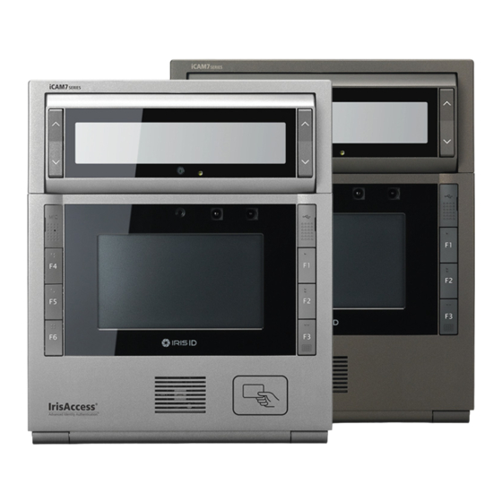
iCAM7111S-U1T (Titanium Color)
4.3" LCD
(7100S only)
EASY
iCAM7101S / iCAM7101S-T
iCAM7111S-U1 / iCAM7111S-U1T
iCAM7 series
iCAM7101S (Black Color)
Hardware Guide L wrench
Advertisement
Table of Contents

Summary of Contents for IRIS iCAM7100S SERIES
- Page 1 • Fully automatic dual iris capture • Simple non-intrusive, non-contact user interface • Integrated megapixel face camera with LED flash • ISO/ANSI compliant iris and face images • 4.3” color touch screen LCD • Integrated contactless smart card reader [optional] •...
-
Page 2: Hardware Information
Hardware Information Front View Camera Unit Up / Down Tilt Buttons Alignment Guide Mirror Face Camera Face Camera Flash CCTV Camera (optional) Proximity Sensor Screw Cap Screw Cap Function Buttons Function Buttons Speaker 4.3” Color Touch Screen LCD Card Reader (optional) Status LED Interface Panel Bottom View... - Page 3 Hardware Information Inside Installation Plate Screw RTC Battery Tamper Power On/Off Switch Switch Power LED Wiring Legend Guide Ethernet Connection / USB 2.0 (Bottom) Input / Output Connections Power Connection External GPIO External Speaker Jack RS232 / RS485 / Factory Default Button RS422 Serial Relay Output Wiegand...
- Page 4 Installation Guidelines 1. Recommended Mounting Information Bottom of 7.01” 2.52” Mirror (178mm) (64mm) 61” 8.31” (155cm) (211mm) 54.3” (138cm) NOTE This is based on the assumption that users’ average height is 5‘7”(170cm) Floor The recommended mounting height for the iCAM7 series is 138cm (54.3inches) from the floor to the bottom of the unit.
- Page 5 IMPORTANT: IT IS RECOMMENDED TO SUPPLY THE CORRECT AMOUNT OF POWER TO THIS UNIT. AN OVER OR UNDER VOLTAGE APPLIED TO THIS PRODUCT MAY CAUSE PERMANENT DAMAGE AND VOID THE WARRANTY. iCAM Installation iCAM7 series Mounting & Stand Solutions The iCAM7 series unit can be fitted to a surface mount (available out-of-the-box), recess mount (with optional recess mounting kit), or optional desktop stand.
- Page 6 Place the installation plate on the desired wall and screw into wall. Feed any needed wiring through the installation plate hole (i.e.: Power, Ethernet, etc). Attach the installation plate to the wall surface using the appropriate fastener (recommended #10 screws) and anchors for the wall material. Another option is to mount and fasten the installation plate to a previously installed electrical gang box.
- Page 7 Remove protective film from RTC battery. Power Supply Ethernet Connector Cable Power on Before wiring unit, confirm the power is in the off position. Route and connect the Power and Ethernet wires to iCAM7 series. If connecting any other wiring such as Wiegand, GPI/O to the iCAM, review the following NOTE section “Wire Connection Details”...
- Page 8 Wire Connection Details External GPIO GPIO3 and 4 can be used to control the tilt position of the tilt unit of an iCAM7 series. Use GPIO3 and GND for up tilting. Use GPIO4 and GND for down tilting. GPIO Specifications: •...
- Page 9 RS232 Output RS232 serial communication port for connection with an access panel or to other computer equipment. When configured, the Card ID associated with the user is output from the RS232 output port upon a successful identification. To RS232 port of computer or access system RS232...
-
Page 10: Relay Output
Relay Output IMPORTANT: ONLY KNOWLEDGEABLE PROFESSIONAL INSTALLERS SHOULD BE USED TO INSTALL ALL ELECTRONIC ENTRY/EXIT LOCKING DEVICES. DIRECT CONNECTION OF ELECTRONIC ENTRY/EXIT LOCKING DEVICES SHOULDN’T BE MADE FROM THE RELAY OUTPUTS ON THE ICAM. IT IS THE RESPONSIBILITY OF THE INSTALLER TO ASSURE THAT THE INSTALLATION IS PERFORMED IN ACCORDANCE WITH ALL COUNTRY/STATE/ LOCAL FIRE AND SAFETY REGULATIONS AND THAT ANY 3RD PARTY PRODUCTS USED WILL NOT CREATE A HAZARD. -
Page 11: Wiegand Input
Wiegand Input Wiegand input is available on the iCAM for connection from 3rd party proximity card readers. This connection can provide 12VDC and a maximum 300mA current to a proximity card reader. Wiegand Intput External Prox Card 12VDC Reader DATA_0 DATA_1 GROUND External Speaker Out... - Page 12 iCAM Configuration The iCAM 7 Series camera contains a configuration interface called the iCAM Configuration. This configuration interface allows the installer to setup the iCAM’s IP Address, IrisServer connection, and other configuration options. How to access the iCAM Configuration interface From a PC with an internet browser connected to the network (that the iCAM7 series unit is connected to), type the IP address of the iCAM.
-
Page 13: How To Operate
How to Operate 11~15” (28-38cm) Tilt down -25 Degrees Read distance 14inches away Tilt up +35 Degrees Read distance 14inches The on-unit up/down tilt buttons can be used to adjust the tilt angle; or an external mounted switch can be wired to control up/down tilt via GPI. - Page 14 Restoring The Unit to Factory Default Factory Default Button The Factory Default Button can be used to restore the settings of the iCAM 7 Series to factory default. This button is located inside of the unit next to the power switch (see image), and can be used in two different ways: Factory Default Button Function Procedure...
- Page 15 Memo Serial Number: Unit IP Address: Installation Date: Option 3 Iris Server IP: Option 3 Security ID: Note:...
-
Page 16: General Information
The iCAM7 series multifactor iris biometric reader contains a high-speed multi-sensor optical system which provides ISO compliant iris images. The iCAM7 series also contains a color face camera, an intuitive user interface, a built-in iris biometric template creation and matching processor, and an optional integrated card reader.
Need help?
Do you have a question about the iCAM7100S SERIES and is the answer not in the manual?
Questions and answers