Vega VEGAFLEX 81 Operating Instructions Manual
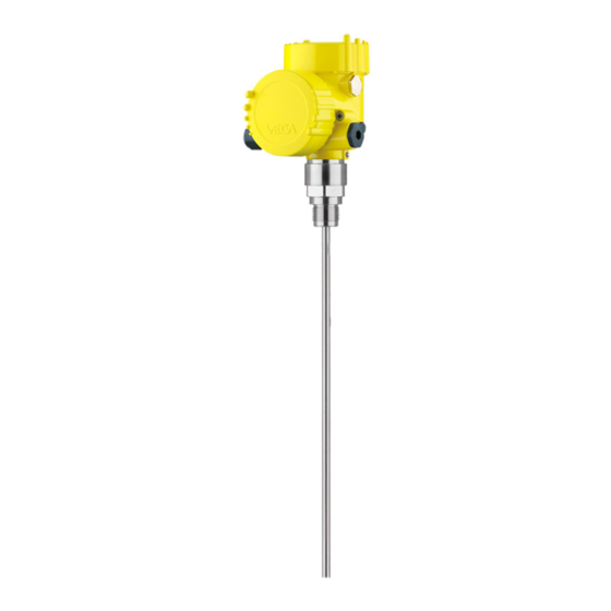
Tdr sensor for continuous level and
interface measurement of liquids
Hide thumbs
Also See for VEGAFLEX 81:
- Operating instructions manual (100 pages) ,
- Quick setup manual (24 pages) ,
- Mounting instructions (20 pages)

Related Manuals for Vega VEGAFLEX 81


Summary of Contents for Vega VEGAFLEX 81
-
Page 1: Operating Instructions
Operating Instructions TDR sensor for continuous level and interface measurement of liquids VEGAFLEX 81 4 … 20 mA/HART two-wire Document ID: 41824... -
Page 2: Quick Start
Ground terminal for connection of the cable screen See also chapter "Connecting to power supply" Set parameters For standard applications we recommend selecting the "Quick setup" in the display and adjustment module. VEGAFLEX 81 • 4 … 20 mA/HART two-wire... - Page 3 For this adjustment, the distance is entered when the vessel is full and nearly empty. If these values are not known, an adjustment with other distances, for example, 10 % and 90 % is also possible. Starting VEGAFLEX 81 • 4 … 20 mA/HART two-wire...
- Page 4 1. In the menu "Additional settings", menu item "Damping" you can adjust the requested damping of the output signal. 2. Select the parameter of the current output and the output charac- teristics in the menu item "Current output". VEGAFLEX 81 • 4 … 20 mA/HART two-wire...
-
Page 5: Table Of Contents
Set up with the quick setup ..................... 60 Saving the parameter adjustment data ................64 Set up with other systems DD adjustment programs ....................65 Field Communicator 375, 475 ..................65 Diagnostics and service Maintenance ........................66 VEGAFLEX 81 • 4 … 20 mA/HART two-wire... - Page 6 Please note the Ex-specific safety information for installation and op- eration in Ex areas. These safety instructions are part of the operating instructions manual and come with the Ex-approved instruments. Editing status: 2013-06-11 VEGAFLEX 81 • 4 … 20 mA/HART two-wire...
-
Page 7: About This Document
This arrow indicates a single action. Sequence of actions Numbers set in front indicate successive steps in a procedure. Battery disposal This symbol indicates special information about the disposal of bat- teries and accumulators. VEGAFLEX 81 • 4 … 20 mA/HART two-wire... -
Page 8: For Your Safety
During work on and with the device the required personal protective equipment must always be worn. Appropriate use VEGAFLEX 81 is a sensor for continuous level measurement. You can find detailed information on the application range in chapter "Product description". -
Page 9: Namur Recommendations
The environment management system is certified according to DIN EN ISO 14001. Please help us fulfill this obligation by observing the environmental instructions in this manual: • Chapter "Packaging, transport and storage" • Chapter "Disposal" VEGAFLEX 81 • 4 … 20 mA/HART two-wire... -
Page 10: Product Description
Order-specific sensor data for an electronics exchange (XML) • Test certificate pressure transmitters (PDF) Go to www.vega.com, "VEGA Tools" and "Serial number search". As an alternative, you can find the data via your Smartphone: • Download the Smartphone-App "VEGA Tools" from the "Apple App Store "... -
Page 11: Principle Of Operation
– if necessary, further certificates Principle of operation Application area The VEGAFLEX 81 is a level sensor with cable or rod probe for continuous level or interface measurement, suitable for applications in liquids. High frequency microwave pulses are guided along a steel cable or... - Page 12 Upon reaching the product surface, a part of the microwave im- pulses is reflected. The other part passes through the upper product and is reflected by the interface. The running times to the two product layers are processed by the instrument. VEGAFLEX 81 • 4 … 20 mA/HART two-wire...
- Page 13 Example: upper medium dielectric constant 2, lower medium at least dielectric constant 12. Gas phase (L3) • Air or gas mixture • Gas phase - dependent on the application, gas pahse does not always exist (d2 = 0) VEGAFLEX 81 • 4 … 20 mA/HART two-wire...
-
Page 14: Packaging, Transport And Storage
The interface adapter VEGACONNECT enables the connection of VEGACONNECT communication-capable instruments to the USB interface of a PC. For parameter adjustment of these instruments, the adjustment software PACTware with VEGA-DTM is required. VEGAFLEX 81 • 4 … 20 mA/HART two-wire... - Page 15 3 Product description You can find further information in the operating instructions "Interface adapter VEGACONNECT" (Document-ID 32628). VEGADIS 81 The VEGADIS 81 is an external display and adjustment unit for VEGA plics sensors. ® For sensors with double chamber housing the interface adapter "DISADAPT"...
- Page 16 You can find further information in the operating instructions manual "Bypass tube VEGAPASS 81". Spacer If you mount the VEGAFLEX 81 in a bypass tube or standpipe, you have to avoid contact to the bypass tube by using a spacer at the probe end.
-
Page 17: Mounting
Mounting instructions Installation position Mount VEGAFLEX 81 in such a way that the distance to vessel instal- lations or to the vessel wall is at least 300 mm (12 in). In non-metallic VEGAFLEX 81 • 4 … 20 mA/HART two-wire... - Page 18 When installing rod or cable probes in vessels without metal walls, e.g. in plastic vessels, the measured value can be influenced by strong electromagnetic fields (emitted interference according to EN 61326: class A). In this case, use a probe with coaxial version. VEGAFLEX 81 • 4 … 20 mA/HART two-wire...
- Page 19 You can find further information under "Setup procedure". _ < DN40 ... DN150 _ < > DN150 ... DN200 Fig. 9: Mounting socket When welding the socket, make sure that the socket is flush with the vessel top. VEGAFLEX 81 • 4 … 20 mA/HART two-wire...
- Page 20 - measurement in these areas is not possible (dead band). The length of the cable can be used all the way to the end only when measuring conductive VEGAFLEX 81 • 4 … 20 mA/HART two-wire...
- Page 21 If durability is no problem, then we recommend the use of metal standpipes. When the VEGAFLEX 81 is used in standpipes or bypass tubes, contact with the tube wall must be avoided. We recommend for this purpose a cable probe with centering weight.
- Page 22 Make sure that the probe cable is not completely taut. Avoid tensile loads on the cable. Avoid undefined vessel connections, i.e. the connection must be either grounded reliably or isolated reliably. Any undefined change of this requirement can lead to measurement errors. VEGAFLEX 81 • 4 … 20 mA/HART two-wire...
- Page 23 Let the probe length determine automatically by the instrument to compensate the resulting running time changes. You can find further information in the supplementary instructions of the rod extension. VEGAFLEX 81 • 4 … 20 mA/HART two-wire...
-
Page 24: Connecting To Power Supply
Connection to signal con- The signal conditioning instruments VEGAMET and VEGASCAN ditioning instruments have digital sensor recognition. When connecting VEGAFLEX 81, an up-to-date version of the signal conditioning instrument software is required. For a software update go to "www.vega.com/downloads" and "Software". -
Page 25: Connecting
4. Remove approx. 10 cm (4 in) of the cable mantle, strip approx. 1 cm (0.4 in) of insulation from the ends of the individual wires 5. Insert the cable into the sensor through the cable entry VEGAFLEX 81 • 4 … 20 mA/HART two-wire... - Page 26 7. Check the hold of the wires in the terminals by lightly pulling on them 8. Connect the screen to the internal ground terminal, connect the outer ground terminal to potential equalisation VEGAFLEX 81 • 4 … 20 mA/HART two-wire...
-
Page 27: Wiring Plan, Single Chamber Housing
The following illustrations apply to the non-Ex as well as to the Ex-ia version. Electronics compartment 4...20mA 6 7 8 Fig. 17: Electronics compartment, double chamber housing Internal connection to the connection compartment For display and adjustment module or interface adapter VEGAFLEX 81 • 4 … 20 mA/HART two-wire... - Page 28 - Radio module PLICS- MOBILE Status SIM-Card Test Fig. 19: Connection compartment radio module PLICSMOBILE Voltage supply You can find detailed information on connection in the supplementary instructions "PLICSMOBILE GSM/GPRS radio module". VEGAFLEX 81 • 4 … 20 mA/HART two-wire...
-
Page 29: Wiring Plan, Ex-D-Ia Double Chamber Housing
If an instrument with Ex-d-ia approval is used, HART multidrop op- eration is not possible. Connection compartment 4...20mA Fig. 21: Connection compartment, Ex-d double chamber housing Voltage supply, signal output Ground terminal for connection of the cable screen VEGAFLEX 81 • 4 … 20 mA/HART two-wire... -
Page 30: Wiring Plan - Version Ip 66/Ip 68, 1 Bar
Pin 4 Black Wiring plan - version IP 66/IP 68, 1 bar Wire assignment, con- nection cable Fig. 24: Wire assignment fix-connected connection cable brown (+) and blue (-) to power supply or to the processing system Shielding VEGAFLEX 81 • 4 … 20 mA/HART two-wire... -
Page 31: Supplementary Electronics
PC • Indication of the status message "F 105 Determine measured value" on the display or PC • The output signal jumps to the set error current VEGAFLEX 81 • 4 … 20 mA/HART two-wire... - Page 32 As soon as a plausible measured value is found, the corresponding current is outputted to the signal cable. The value corresponds to the actual level as well as the settings already carried out, e.g. factory setting. VEGAFLEX 81 • 4 … 20 mA/HART two-wire...
-
Page 33: Set Up With The Display And Adjustment Module
The display and adjustment module is powered by the sensor, an ad- ditional connection is not necessary. Fig. 27: Insertion of the display and adjustment module with single chamber housing into the electronics compartment VEGAFLEX 81 • 4 … 20 mA/HART two-wire... -
Page 34: Adjustment System
Adjustment system Fig. 29: Display and adjustment elements LC display Adjustment keys • Key functions [OK] key: – Move to the menu overview VEGAFLEX 81 • 4 … 20 mA/HART two-wire... -
Page 35: Parameter Adjustment - Quick Setup
Any values not confirmed with [OK] will not be saved. Switch-on phase After switching on, the VEGAFLEX 81 carries out a short self-test where the device software is checked. The output signal transmits a fault signal during the switch-on phase. - Page 36 In this menu item, you can enter the max. adjustment for the level. Enter the appropriate distance value in m (corresponding to the percentage value) for the full vessel. The distance refers to the sensor VEGAFLEX 81 • 4 … 20 mA/HART two-wire...
- Page 37 Enter the actual distance from the sensor to the product surface. All interfering signals in this section are detected by the sensor and stored. VEGAFLEX 81 • 4 … 20 mA/HART two-wire...
-
Page 38: Parameter Adjustment - Extended Adjustment
"->" key you jump to the next position. You can enter names with max. 19 characters. The character set comprises: • Capital letters from A … Z • Numbers from 0 … 9 VEGAFLEX 81 • 4 … 20 mA/HART two-wire... - Page 39 You have the option of choosing the demonstration mode. This mode is only suitable for test and demonstration purposes. In this mode, the sensor ignores the parameters of the application and reacts immedi- ately to each change. VEGAFLEX 81 • 4 … 20 mA/HART two-wire...
- Page 40 In this menu item you can enter the max. adjustment for the level. With Level interface measurement this is the maximum total level. Adjust the requested percentage value with [+] and store with [OK]. VEGAFLEX 81 • 4 … 20 mA/HART two-wire...
- Page 41 If you select "Yes", the current setting will be displayed. If you have selected "No", you can enter the adjustment for the inter- face separately. Enter the requested percentage value. VEGAFLEX 81 • 4 … 20 mA/HART two-wire...
- Page 42 If the volume should not be displayed in percent but e.g. in l or kg, a scaling can be also set in the menu item "Display". VEGAFLEX 81 • 4 … 20 mA/HART two-wire...
- Page 43 Fig. 30: Vessel height und socket correction value D Vessel height +h Positive socket correction value -h Negative socket correction value VEGAFLEX 81 • 4 … 20 mA/HART two-wire...
- Page 44 You can accept the scaling of the level measurement also for the interface measurement. If you select "Yes", the current setting is displayed. If you have selected "No", you can enter the scaling for the interface separately. VEGAFLEX 81 • 4 … 20 mA/HART two-wire...
- Page 45 In the menu item "Current output mode" you determine the output mode characteristics and reaction of the current output in case of failure. The default setting is output characteristics 4 … 20 mA, failure mode < 3.6 mA. VEGAFLEX 81 • 4 … 20 mA/HART two-wire...
- Page 46 TV (third value) and the fourth HART value QV (quarter value) of the sensor displayed. The values cannot be changed in the display and adjustment module. To change these values, you have to use the adjustment software PACTware. VEGAFLEX 81 • 4 … 20 mA/HART two-wire...
- Page 47 In the menu item "Lock/unlock adjustment", you can protect the Lock/release setup - Ad- justment sensor parameters against unauthorized modification. The PIN is activated/deactivated permanently. The following adjustment functions are possible without entering the PIN: VEGAFLEX 81 • 4 … 20 mA/HART two-wire...
- Page 48 Display - Displayed value In this menu item, you define the indication of the measured value on the display. You can display two different measured values. In this menu item, you define measured value 2. VEGAFLEX 81 • 4 … 20 mA/HART two-wire...
- Page 49 If you have selected interface measurement under the menu item "Setup - Application", the peak values of the interface measurement are displayed in addition to the peak values of the level measurement. VEGAFLEX 81 • 4 … 20 mA/HART two-wire...
- Page 50 In this menu item you can simulate measured values via the current output. This allows the signal path to be tested, e.g. via downstream indicating instruments or the input card of the control system. VEGAFLEX 81 • 4 … 20 mA/HART two-wire...
- Page 51 Entering a 4-digit PIN protects the sensor data against unauthorized access and unintentional modification. In this menu item, the PIN is displayed or edited and changed. However, this menu item is only VEGAFLEX 81 • 4 … 20 mA/HART two-wire...
- Page 52 Menu item Default value Modified value Block adjustment Released Measurement loop name Sensor Units Distance unit: mm Temperature unit: °C Probe length Length of the probe Ex factory Medium type Liquid Application Level, vessel VEGAFLEX 81 • 4 … 20 mA/HART two-wire...
- Page 53 Current output - Output characteristics 0 … 100 % correspond to 4 … 20 mA Current output - Reaction in case of failure ≤ 3.6 mA Current output - Min. 3.8 mA VEGAFLEX 81 • 4 … 20 mA/HART two-wire...
- Page 54 Not active with measured value Device memory - Measured value memory - Stop Not active with measured value Device memory - Measured value memory - Stop Not active recording when memory is full VEGAFLEX 81 • 4 … 20 mA/HART two-wire...
- Page 55 In this menu item you gain access to the protected area where Special parameters you can enter special parameters. In exceptional cases, individual parameters can be modified in order to adapt the sensor to special requirements. VEGAFLEX 81 • 4 … 20 mA/HART two-wire...
- Page 56 In this menu item, the date of factory calibration of the sensor as well date as the date of the last change of sensor parameters are displayed via the display and adjustment module or via the PC. VEGAFLEX 81 • 4 … 20 mA/HART two-wire...
-
Page 57: Saving The Parameter Adjustment Data
If it is necessary to exchange a sensor, the display and adjustment module is inserted into the replacement instrument and the data are likewise written into the sensor via the menu item "Copy sensor data". VEGAFLEX 81 • 4 … 20 mA/HART two-wire... -
Page 58: Setup With Pactware
With power supply units with integrated HART resistance (internal resistance approx. 250 Ω), an additional external resistance is not necessary. This applies, e.g. to the VEGA instruments VEGATRENN 149A, VEGAMET 381, VEGAMET 391. Common Ex separators are also usually equipped with a sufficient current limitation resistance. In... -
Page 59: Parameter Adjustment With Pactware
An assistant for simple project configuration simplifies the adjustment considerably. Saving/printing the project as well as import/export functions are also part of the standard version. VEGAFLEX 81 • 4 … 20 mA/HART two-wire... -
Page 60: Set Up With The Quick Setup
Extended adjustment Maintenance Quick setup With quick setup you can carry out the parameter adjustment of VEGAFLEX 81 for your application in just a few simple steps. The assistant-driven adjustment includes the basic settings for simple, reliable setup and commissioning. Information: If the function is inactive, then possibly no instrument is connected. - Page 61 If this function is inactive, the medium type your instrument is suitable for was already preset. Information: In special cases you can change the medium type. This setting can be changed under "Extended adjustment". VEGAFLEX 81 • 4 … 20 mA/HART two-wire...
- Page 62 (sensor reference plane) to the surface of the product. Adjustment for the level and interface measurement If you have selected interface measurement in the previous menu, then you can enter the values for the min. and max. adjustment of VEGAFLEX 81 • 4 … 20 mA/HART two-wire...
- Page 63 You can use this file later on to restore the instrument parameter adjustment. The complete data set is down- loaded from the device. This procedure can last several minutes. VEGAFLEX 81 • 4 … 20 mA/HART two-wire...
-
Page 64: Saving The Parameter Adjustment Data
PIN is entered again. Saving the parameter adjustment data We recommend documenting or saving the parameter adjustment data via PACTware. That way the data are available for multiple use or service purposes. VEGAFLEX 81 • 4 … 20 mA/HART two-wire... -
Page 65: Set Up With Other Systems
The files can be downloaded at www.vega.com/downloads under "Software". Field Communicator 375, 475 Device descriptions for the instrument are available as EDD for pa- rameter adjustment with the Field Communicator 375 or 475. VEGAFLEX 81 • 4 … 20 mA/HART two-wire... -
Page 66: Diagnostics And Service
Changes in the measure- ment conditions during operation or buildup on the sensor can thus be recognized. The echo curve of the setup is stored via: • PC with PACTware/DTM • Control system with EDD VEGAFLEX 81 • 4 … 20 mA/HART two-wire... -
Page 67: Status Messages
This status message is inactive by default. It can be activated by the user via PACTware/DTM or EDD. Maintenance: Due to external influences, the instrument function is limited. The measurement is affected, but the measured value is VEGAFLEX 81 • 4 … 20 mA/HART two-wire... - Page 68 4-wire power supply unit F125 – Temperature of the elec- – Check ambient temperature tronics in the non-specified – Isolate electronics Unpermissi- section – Use instrument with higher ble electronics temperature range temperature VEGAFLEX 81 • 4 … 20 mA/HART two-wire...
- Page 69 Text mes- sage S600 – Temperature of the pro- – Check ambient temperature cessing electronics in the – Isolate electronics Unpermissi- non-specified section – Use instrument with higher ble electronics temperature range temperature VEGAFLEX 81 • 4 … 20 mA/HART two-wire...
- Page 70 – Clean or exchange process – Process component or component or probe probe contaminated or defective M504 – Hardware defect – Exchanging the electronics – Send instrument for repair Error on an device inter- face VEGAFLEX 81 • 4 … 20 mA/HART two-wire...
-
Page 71: Rectify Faults
Error Cause Rectification 4 … 20 mA signal – Level fluctua- – Set damping according to the not stable tions instrument via the display and adjustment module or PACTware/ VEGAFLEX 81 • 4 … 20 mA/HART two-wire... - Page 72 "Hold value" • In case of a too low level indication, the reason could be a line resistance that is too high VEGAFLEX 81 • 4 … 20 mA/HART two-wire...
- Page 73 The sensor goes into – If possible, switch off the func- overfill protection mode. The tion "Overfill protection" time max. level (0 m distance) as well as the status message "Overfill protection" are output- ted. VEGAFLEX 81 • 4 … 20 mA/HART two-wire...
-
Page 74: Exchanging The Electronics Module
24 hour service hotline Should these measures not be successful, please call in urgent cases the VEGA service hotline under the phone no. +49 1805 858550. The hotline is also available outside normal working hours, seven days a week around the clock. -
Page 75: Exchanging The Cable/Rod
6. Enter new probe length and if necessary the new probe type and then carry out a fresh adjustment (see "Setup procedure, Carry- ing out min. adjustment - Carrying out max. adjustment"). VEGAFLEX 81 • 4 … 20 mA/HART two-wire... -
Page 76: Software Update
Software update The following components are required to update the sensor soft- ware: • Sensor • Voltage supply • Interface adapter VEGACONNECT • PC with PACTware • Current sensor software as file VEGAFLEX 81 • 4 … 20 mA/HART two-wire... -
Page 77: How To Proceed In Case Of Repair
Attach the completed form and, if need be, also a safety data sheet outside on the packaging • Please contact for the return shipment the agency serving you. You can find the agency on our home page www.vega.com. VEGAFLEX 81 • 4 … 20 mA/HART two-wire... -
Page 78: Dismounting
Pass the instrument directly on to a spe- cialised recycling company and do not use the municipal collecting points. These may be used only for privately used products according to the WEEE directive. VEGAFLEX 81 • 4 … 20 mA/HART two-wire... -
Page 79: Supplement
Ʋ Pipe thread, cylindrical (ISO 228 T1) G¾, G1, G1½ according to DIN 3852-A Ʋ American pipe thread, conical ¾ NPT, 1 NPT, 1½ NPT (ASME B1.20.1) Ʋ Flanges e.g. DIN from DN 25, ANSI from 1" VEGAFLEX 81 • 4 … 20 mA/HART two-wire... - Page 80 Ʋ Plastic housing max. 10 Nm (7.376 lbf ft) Ʋ Aluminium/Stainless steel housing max. 50 Nm (36.88 lbf ft) Input variable Measured variable Level of liquids Min. dielectric constant of the medium VEGAFLEX 81 • 4 … 20 mA/HART two-wire...
- Page 81 Range of the output signal 3.8 … 20.5 mA/HART (default setting) Fulfilled HART specification Signal resolution 0.3 µA Failure signal current output (adjustable) Last valid measured value, ≥ 21 mA, ≤ 3.6 mA VEGAFLEX 81 • 4 … 20 mA/HART two-wire...
- Page 82 +860 … +1060 mbar/+86 … +106 kPa (+12.5 … +15.4 psig) Installation reference conditions The output values can be assigned individually The indication values can be assigned individually The indication values can be assigned individually VEGAFLEX 81 • 4 … 20 mA/HART two-wire...
- Page 83 " " (0.787 ") Fig. 48: Deviation VEGAFLEX 81 in rod version in water Dead band - no measurement possible in this area Probe length With interface measurement = 2.0 Depending on the installation conditions, there can be deviations which can be rectified with an adaptation of the adjustment or a change of the measured value offset in the DTM service mode The dead bands can be optimizes by a false signal suppression.
- Page 84 (5.906 (11.811 " ") (2.756 ") 0,05 m (1.97 ") Fig. 49: Deviation VEGAFLEX 81 in rod version in oil Dead band - no measurement possible in this area Probe length 15 mm (0.591 ") 2 mm (0.079 ") -2 mm (-0.079...
- Page 85 " ") (1.969 ") 0,08 m (3.15 ") Fig. 51: Deviation VEGAFLEX 81 in cable version ø 2 mm (0.079 in), in oil Dead band - no measurement possible in this area Probe length 20 mm (0.787 " 15 mm (0.591...
-
Page 86: Ambient Conditions
Time span after a sudden measuring distance change by max. 0.5 m in liquid applications, max 2 m with bulk solids applications, until the output signal has taken for the first time 90 % of the final value (IEC 61298-2). VEGAFLEX 81 • 4 … 20 mA/HART two-wire... - Page 87 Fig. 53: Ambient temperature - process temperature, standard version Ambient temperature Process temperature (depending on the seal material) Maximum permissible temperature - standard Limited temperature range - plastic housing and stainless steel housing, electropolished VEGAFLEX 81 • 4 … 20 mA/HART two-wire...
- Page 88 M12 x 1 plug Wire cross-section (spring-loaded terminals) Ʋ Massive wire, cord 0.2 … 2.5 mm² (AWG 24 … 14) Ʋ Stranded wire with end sleeve 0.2 … 1.5 mm² (AWG 24 … 16) VEGAFLEX 81 • 4 … 20 mA/HART two-wire...
- Page 89 Ʋ Inspection window Polyester foil Integrated clock Date format Day.Month.Year Time format 12 h/24 h Time zone Ex factory Measurement electronics temerature Resolution 1 °C (1.8 °F) Accuracy ±1 °C (1.8 °F) VEGAFLEX 81 • 4 … 20 mA/HART two-wire...
-
Page 90: Dimensions
Instruments with approvals can have different technical data depending on the version. For that reason the associated approval documents of these instruments must be carefully noted. They are part of the delivery or can be downloaded under www.vega.com and "VEGA Tools" as well as under "Downloads" and "Approvals". - Page 91 ½ NPT Fig. 56: Housing versions in protection IP 66/IP 68 (0.2 bar) - with integrated display and adjustment module the housing is 9 mm/0.35 in higher Single chamber version Double chamber version VEGAFLEX 81 • 4 … 20 mA/HART two-wire...
- Page 92 Fig. 58: Housing versions in protection IP 66/IP 68 (0.2 bar) - with integrated display and adjustment module the housing is 9 mm/0.35 in higher Single chamber version, electropolished Single chamber version, precision casting Double chamber version, precision casting VEGAFLEX 81 • 4 … 20 mA/HART two-wire...
- Page 93 (3.39") (3.15") (3.11") M16x1,5 M20x1,5 M20x1,5/ ½ NPT M20x1,5/ ½ NPT Fig. 59: Housing versions in protection IP 66/IP 68 (1 bar) - with integrated display and adjustment module the housing is 9 mm/0.35 in higher Single chamber version, electropolished Single chamber version, precision casting Double chamber version, precision casting VEGAFLEX 81 • 4 … 20 mA/HART two-wire...
- Page 94 ø 20 mm ø 20 mm (0.79") (0.79") (0.79") Fig. 60: VEGAFLEX 81, threaded version with gravity weight (all gravity weights with thread M8 for eye-bolt) Sensor length, see chapter "Technical data" VEGAFLEX 81 • 4 … 20 mA/HART two-wire...
- Page 95 ø 95 mm (3.74 in) Cable version ø 2 mm (0.079 in) with centering weight (see supplementary instructions "Centering") Cable version ø 4 mm (0.157 in) with centering weight (see supplementary instructions "Centering") VEGAFLEX 81 • 4 … 20 mA/HART two-wire...
- Page 96 ø 8 mm ø 12¨mm (0.32") (0.47") Fig. 62: VEGAFLEX 81, threaded version Sensor length, see chapter "Technical data" Rod version ø 8 mm (0.315 in) Rod version ø 12 mm (0.472 in) VEGAFLEX 81 • 4 … 20 mA/HART two-wire...
- Page 97 Les lignes de produits VEGA sont globalement protégées par des droits de propriété intellec- tuelle. Pour plus d'informations, on pourra se référer au site www.vega.com. VEGA lineas de productos están protegidas por los derechos en el campo de la propiedad indus- trial. Para mayor información revise la pagina web www.vega.com.
- Page 98 EDD (Enhanced Device Description) 65 Electronics and connection compartment, single chamber housing 27 Packaging 14 Electronics compartment, double chamber Peak value 49, 50 housing 27 PIN 51 Electronics compartment with Ex-d double Potential equalisation 25 VEGAFLEX 81 • 4 … 20 mA/HART two-wire...
- Page 99 Scaling measured value 44, 45 Sensor characteristics 57 Sensor status 49 Service hotline 74 Shielding 25 Simulation 50 Special parameters 55 Status messages 67 Storage 14 Type plate 10 Units 39 Voltage supply 24 VEGAFLEX 81 • 4 … 20 mA/HART two-wire...
- Page 100 Subject to change without prior notice © VEGA Grieshaber KG, Schiltach/Germany 2013 VEGA Grieshaber KG Phone +49 7836 50-0 Am Hohenstein 113...
Need help?
Do you have a question about the VEGAFLEX 81 and is the answer not in the manual?
Questions and answers