Table of Contents
Advertisement
Available languages
Available languages
Manuale per il collegamento e l'uso
Installation and operation manual
Manuel pour le raccordement et l'emploi
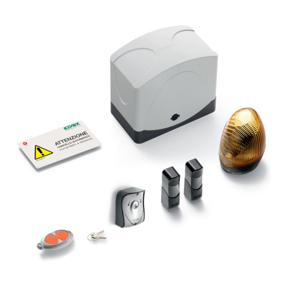
Art. ESK4
Automazione cancello scorrevole peso max 400 Kg con radiocomando a 433 MHz
Sliding gates automatic system weight 400 Kg and radio control with 433 MHz operating frequency
Actionneurs pour grilles à portes coulissantes Poids 400 Kg set radiocommande avec fréquence de
travail de 433 MHz
Advertisement
Table of Contents

Related Manuals for Elvox ESK4

Summary of Contents for Elvox ESK4
- Page 1 Manuale per il collegamento e l’uso Installation and operation manual Manuel pour le raccordement et l’emploi Art. ESK4 Automazione cancello scorrevole peso max 400 Kg con radiocomando a 433 MHz Sliding gates automatic system weight 400 Kg and radio control with 433 MHz operating frequency Actionneurs pour grilles à...
-
Page 2: Important Security Information
(au moyen d'une plaque appro- randa o barriera che sono comandati a distanza . ELVOX S.p.A. will not accept liability for any da- priée) qu'ils sont gérés à distance. mediante apposito cartello. mage caused by the incorrect installation of de- . - Page 3 Fusibile - Fuse - Fusible 4A (T41) Scheda carica batteria Trasformatore (ECB1) opzionale Alimentazione rete Programmazione Transformer Batteria opzionale Pulsante Apri/Chiudi Battery charge card Mains power supply Settings Transformeteur Open/Close button Battery optional (ECB1) optional Alimentation réseau Programmation 230V-12V 150VA Alimentation réseau Bouton Ouvrir/Fermer Carte charge batterie...
-
Page 4: Caratteristiche Generali
CARATTERISTICHE GENERALI Automazione, serie ES, per cancelli scorrevoli residenziali e condominiali ad uso intensivo. L’attuatore elettromeccanico irreversibile è dotato di un moto- re in bassa tensione, 12 Vcc, e uno sblocco meccanico che permette di aprire e chiudere il cancello manualmente. Il motore aziona un gruppo riduttorre, lubrificato con grasso permanente, racchiuso in una fusione d’alluminio di grosso spessore ma di ridottissimo ingombro. - Page 5 INSTALLAZIONE MECCANICA Per un corretto funzionamento dell’automazione la struttura del cancello esistente, o da realizzare, deve presentare i seguenti requisiti: - Le ruote del cancello siano montate in posizione tale da dare stabilità al cancello stesso e che siano in buono stato ed efficienti. - La rotaia sia libera diritta e pulita in tutta la sua lunghezza con battute d’arresto obbligatorie sia in apertura che in chiusura.
-
Page 6: Sblocco Manuale
Installazione della cremagliera: 1 -Chiudere completamente il cancello. 2 -Si deve garantire un gioco di 2mm. tra pignone e cremagliera su tutta la lunghezza del cancello (Fig. 4A). Per fare ciò posizionare gli spessori (in dotazione) come mostra la Fig. 4B e fissare il motoriduttore. N.B. -
Page 7: Installazione Elettrica
Ciascun dispositivo deve essere installato a regola d’arte, seguendo le istruzioni allegate e soprattutto fare eseguire la messa in opera da per- sonale qualificato Elvox rispettando la normativa vigente in ciascun paese. Seguire le istruzioni allegate per il collegamento dei cavi della scheda elettronica di comando;... - Page 8 La scheda EC10 prevede due modalità di funzionamento, a seconda del tipo di automazione che si desidera controllare. Tale modalità è stabilita dalla posizione del dipswitch 8: 1. scorrevole (dipswitch 8 off) 2. barriera (dipswitch 8 on) La modalità viene valutata all'avvio dell'apparecchiatura e, se è stata cambiata rispetto all'ultima accensione, tutti i parametri vengono ri- portati a default.
- Page 9 FUNZIONAMENTO APPARECCHIATURA SCORREVOLE Richiusura automatica on/off I dipswitch controllano i seguenti parametri: Modalità apertura: off = condominiale on = apre/stop/chiude Prelampeggio on/off Ingresso STPA: off = fotocellula interna on = bordo normale Verifica fotocellule on/off Pedonale/2CAN: off = pedonale on = 2CAN Non usato Modalità...
- Page 10 APPRENDIMENTO CORSA Esistono due modalità di apprendimento della corsa: 1. apprendimento facilitato (Easy Learning) 2. apprendimeno completo (Learning) Per attivare l'apprendimento facilitato (LEARN EASY), tenere premuto il tasto Prog. A. Dopo 2 secondi il LED rosso inizia a lampeggiare lentamente, rilasciando il tasto il LED continuerà a lampeggiare lentamente. È sufficiente quindi premere APCH una volta e l'apprendimento proseguirà...
- Page 11 PROGRAMMAZIONE RADIOCOMANDI Tenendo premuto il tasto Prog. B è possibile attivare la modalità di programmazione e cancellazione dei radiocomandi. NOTA: il primo radiocomando appreso imposta la tipologia di radiocomandi utilizzabili. Le tipologie supportate sono 2: a rolling code e a codice fisso. 1.
-
Page 12: Installazione
FOTOCELLULA RUOTANTE 180° DA ESTERNO PARETE RADIOCOMANDO A 2 CANALI ROLLING CODE FOTOCELLULE ART. EFA1 RADIOCOMANDO ART. ETR2 Fotocellula vesione sincronizzata da esterno parete con possibilità di ruo- Per ogni radiocomando viene memorizzato di serie un codice diverso. tare il circuito 180°. Costituita da ricevitore (RX) e da un trasmettitore (TX) CARATTERISTICHE TECNICHE a raggi infrarossi modulati. - Page 13 Fig. 8 Fig. 9 Fig. 10 COLLEGAMENTO DI 1 COPPIA DI FOTOCELLULE Alimentazione: 12/24Vc.c./c.a COMUNE CONTATTO N.C. COLLEGAMENTO DI DUE COPPIE DI FOTOCELLULE Alimentazione: 12/24Vc.c./c.a COLLEGAMENTO DI DUE COPPIE DI FOTOCELLULE CON FUNZIONE DI SINCRONISMO Alimentazione: 12/24V c.a...
- Page 14 TABELLA DIAGNOSI DI POSSIBILI INCONVENIENTI DELLE AUTOMAZIONI SCORREVOLI CON SCHEDA DI COMANDO A 1 MOTORE POSSIBILI INCONVENIENTI CAUSE VERIFICHE / RIMEDI L’automazione non funziona. Alimentazione di rete assente. Controllare l’interruttore alimentazione trasformatore. Fusibili di alimentazione bruciati. Sostituire i fusibili con altri dello stesso valore.
- Page 15 è regolata dal D.L. n. 24 del 02.02.2002 pubblicato sulla G.U. n. 57 del 08.05.2002. 2) La garanzia dei prodotti ELVOX è di 24 mesi dalla data di acquisto e comprende la riparazione con sostituzione gratuita delle parti che presentano di- fetti o vizi di materiale.
-
Page 16: General Features
GENERAL FEATURES Automation series ES, for residential, groups of flats and sliding gates for intensive operation. The irreversible electromechanical actuator is equipped with a 12V low tension motor and a mechanical lock release which allows you to open and close the gate manually. The motor activates a reducer group, lubri- cated with permanent grease, enclosed in a thick aluminium enclosure, but with reduced dimensions. - Page 17 MECHANICAL INSTALLATION For an automation correct operation the existing gate structure or the one to be carried out, must have the following features: The wheels of the gate are fixed in such a way as to provide gate stability, and are in good working order. The track is free, straight and clean along its entire length with compulsory limit stops fitted at the points of opening and closing.
-
Page 18: Manual Release
Mounting the rack: 1 - Close the gate completely. 2 - A play of 2mm must be ensured between the pinion and the rack for the whole length of the gate (Fig. 4A). To do so position the spacers (provided) as shown in Fig. - Page 19 ELECTRICAL INSTALLATION Each device must be expertly installed, following the enclosed instructions and above all must be set up by qualified Elvox Automation Division approved personnel in accordance with the standards in force in each individual country. Follow the enclosed instructions for the connection of the cables to the electronic control card. Keep in mind that: The control central unit is powered by a security transformer.
-
Page 20: Safety Devices
The EC10 board provides two operating modes, according to the type of automatic gate system that you want to control. This mode is determined by the position of dip switch 8: 1. sliding (dip switch 8 off) 2. barrier (dip switch 8 on) The mode is verified at start-up of the equipment and, if it has been changed since the last start-up, all parameters are reset to default. - Page 21 EQUIPMENT OPERATION SLIDING Automatic reclosure on/off The dip switches control the following parameters: Opening mode: off = condominium on = open/stop/close Pre-flashing On/Off STPA input: off = internal photocell on = normal edge Check photocells on/off Pedestrian/2CAN: off = pedestrian on = 2CAN Not used Operating mode:...
- Page 22 TRAVEL PATH LEARNING There are two travel path learning modes: 1. Easy Learning 2. Learning To activate easy learning, keep the Prog. A button pressed. After 2 seconds the red LED starts to flash slowly, when the button is released the LED will continue to flash slowly.
-
Page 23: Back-Up Battery Operation
RADIO CONTROLS PROGRAMMING Press the Prog. B button to enable programming and deletion of radio controls. NOTE: the first radio control to be learned sets the type of radio controls that can be used. Two types are supported: rolling code and fixed code. 1. -
Page 24: Installation
2 ROLLING CODE RADIO CONTROL CHANNEL PHOTOCELL ROTATING 180° FROM WALL SURFACE RADIO CONTROL ART. ETR2 PHOTOCELLS ART. EFA1 For every radio control a different code is saved in series. Photocell synchronized version for surface flush-mounting with possibility to turn the circuit 180°. Consisting of receiver (RX) and transmitter (TX) with TECHNICAL FEATURES modulated infrared rays. - Page 25 Fig. 8 Fig. 9 Fig. 10 CONNECTION OF A 1-PAIR OF PHOTOELECTRIC CELLS Supply voltage: 12/24VD.C./A.C. COMMON N.C. CONTACT CONNECTION OF A 2-PAIR OF PHOTOELECTRIC CELLS Supply voltage 12/24VD.C./A.C. CONNECTION OF TWO PHOTOCELL PAIRS WITH SYNCHRONISM FUNCTION Supply voltage 12/24V A.C.
- Page 26 DIAGNOSIS TABLE FOR POSSIBLE INCONVENIENCES ON THE SLIDING GATE SYSTEMS WITH 1 MOTOR CONTROL CIRCUIT BOARD POSSIBLE INCONVENIENCES CAUSES CHECK UPS / SOLUTIONS The automation does not work. No supply voltage. Check the transformer supply voltage switch. Supply voltage fuses blown up. Replace the fuses with others with the same value.
-
Page 27: Maintenance
D.L. n. 24 dated 02.02.2002 published in G.U. 57 dated 18.05.2002. 2) The ELVOX product guarantee lasts 24 months from the purchase date and includes the repair with free replacement of parts with defects or material vices. - Page 28 CARACTÉRISTIQUES TECHNIQUES Automatisme série ES pour grilles coulissantes résidentielles, de copropriétés pour emploi intensif. Le moteur électromécanique irréversible est doté d’un moteur à basse tension, 12V c.c., et d’un déverrouillage mécanique qui permet d’ouvrir et fermer la grille manuellement. Le moteur actionne un groupe motoréducteur, lubrifié avec gras permanent, dans une fusion d’aluminium de grosse épaisseur, mais de dimensions très réduites.
- Page 29 INSTALLATION MECANIQUE Pour un correct fonctionnement de l’automatisme la structure du portail existent, ou celui à réaliser doit avoir les requises suivants : - les roulettes de la grille sont montées de façon à donner stabilité à la grille, qu’elles sont en bon état et efficaces; - le rail est libre, droit et propre sur toute la longueur avec butées d’arrêt obligatoires aussi bien en ouverture qu’en fermeture;...
-
Page 30: Déverrouillage Manuel
Installation de la crémaillère: 1 - Fermer complètement la crémallière. 2 - Il faut garantir un jeu de 2mm entre le pignon et la crémallière dans toute la longueur de la grille (Fig. 4A). Pour faire cela positionner les épaisseurs (en dotation) selon la Figure 4B et fixer le motoréducteur. N.B. -
Page 31: Installation Électrique
Chaque dispositif doit être installé dans les règles de l’art, selon les indications jointes et en particulier la mise en œuvre doit être effectuée par du personnel qualifié de Elvox en respectant la réglementation en vigueur dans chaque pays. Suivre les indications jointes pour le branchement des câbles de la carte électronique de commande; ne pas oublier que: La centrale de commande est alimenté... -
Page 32: Dispositifs De Protection
La carte EC10 prévoit deux modes de fonctionnement selon le type d'automatisme à contrôler. Ce mode est établi par la position du com- mutateur dip 8 : 1. coulissant (commutateurs dip 8 off) 2. barrière (commutateurs dip 8 on) Le mode est évalué à la mise en marche de l'appareil et, s'il a été modifié par rapport à la dernière activation, tous les paramètres sont re- pris par défaut. - Page 33 FONCTIONNEMENT DE L'APPAREIL COULISSANT Refermeture automatique on/off Les commutateurs dip contrôlent les paramètres suivants : Mode ouverture : off = copropriété on = ouvrir/stop/fermer Pré-clignotement on/off Entrée STPA : off = photocellule interne on = bord normal Vérification photocellules on/off Piétonne/2CAN : off = piétonne on = 2CAN...
- Page 34 APPRENTISSAGE COURSE Il existe deux modes d'apprentissage de course : 1. apprentissage facile (Easy Learning) 2. apprentissage complet (Learning) Pour activer l'apprentissage facile (LEARN EASY), appuyer de façon continue sur la touche Prog. A. Après 2 secondes, la LED rouge com- mence à...
- Page 35 PROGRAMMATION DES RADIOCOMMANDES En appuyant sur la touche Prog. B, il est possible d'activer le mode de programmation et de suppression des radiocommandes. REMARQUE : la première radiocommande intégrée configure le type de radiocommandes utilisables. Deux types sont supportés : à « rolling code » et à code fixe. 1.
- Page 36 RADIOCOMMANDE AVEC 2 CANAUX “ROLLING CODE” PHOTOCELLULE ROTATIVE 180° MONTAGE EN SAILLIE PHOTOCELLULE ART. EFA1 RADIOCOMMANDE ART. ETR2 Pour chaque radiocommande un code different est memorise de serie. Photocellule version synchronisée pour montage en saillie avec possibi- lité de tourner le circuit de 180°. Comprenant un récepteur (RX) et un CARACTERISTIQUES TECHNIQUES émetteur (TX) à...
- Page 37 Fig. 8 Fig. 9 Fig. 10 CONNEXION DE 1 PAIR DE CELLULES PHOTOÉLECTRIQUES Alimentation 12/24Vc.c./c.a COMMUN CONTACT N.F. CONNEXION DE DEUX PAIRES DE CELLULES PHOTOÉLECTRIQUES Alimentation 12/24Vc.c./c.a CELLULE PHOTOÉLECTRIQUE POUR MONTAGE MURAL EN SAILLIE OU SUR COLONNE Alimentation 12/24V c.a.
- Page 38 TABLE DIAGNOSE INCONVÉNIENTS DES AUTOMATISMES COULISSANTS AVEC CARTE DE COMMANDE À 1 MOTEUR POSSIBLES INCONVÉNIENTS CAUSES CONTRÔLES / SOLUTIONS L’automatisme ne fonctionne pas. Alimentation de réseau absente. Contrôler l’interrupteur alimentation transformateur. Fusibles d’alimentation claqués Remplacer les fusibles avec d’autres de la même valeur.
- Page 39 D.L. n. 24 de 02.02.2002 publié sur la G.U. n. 57 de 08.05.2002. 2) La garantie des produits ELVOX est de 24 mois à partir de la date d’achat et comprend la réparation avec substitution gratuite des parties qui présen- tent des défets ou vices de matériel.
- Page 40 TIMBRE DE L’INSTALLATEUR DATE DE L’INSTALLATION Riproduzione vietata anche parziale. La società ELVOX s.p.a. tutela i diritti sui propri elaborati a termine di Legge. Reproduction forbidden, even partial. ELVOX S.P.A. guards its own rights according to the law. Réproduction défendu, même partiale. La Société ELVOX S.P.A. defende ses droits selon la loi.
Need help?
Do you have a question about the ESK4 and is the answer not in the manual?
Questions and answers