Table of Contents
Advertisement
Advertisement
Table of Contents

Summary of Contents for Tuff Torq K92
-
Page 2: Table Of Contents
Hydrostatic Transmission Motor Disassembly and Assembly (4WD) ....Hydrostatic Transmission Motor Installation ............. Inspection of Transaxle Case ..................K92 Transmission Component Location ..............Ordering Replacement Parts Online ................PTO Brake Removal and Installation ................PTO Clutch Disassembly, Inspection and Assembly .......... - Page 3 Ordering Replacement Parts Online w w w . t u f f t o r q . c o At Tuff Torq, we offer our customers quality products at a modest price. A manufacturer of hydrostatic and gear drive transmissions for the power equipment industry, Tuff...
- Page 4 Tuff Torq K92 Hydrostatic Transaxle Having your Model, and Model Series, click on the serial number to enter the Online Ordering page for you Transaxle (Ref. 6). Navigate through the exploded parts illustration until the desired part has been identified. Take note of the part’s figure number.
- Page 5 Recommended Tools and Equipment Serial Number Location 1. Solenoid Valve Socket 2. Transmission Gear Spacer 3. Bushing, Bearing and Seal Driver Set 4. Press 5. Snap Ring Pliers 6. Knife-Edge Puller 7. Hoist 8. Silicon Sealant 9. Cure primer 10. Thread Lock and Sealer (Medium Strength) General Specifications...
- Page 6 Tuff Torq K92 Hydrostatic Transaxle...
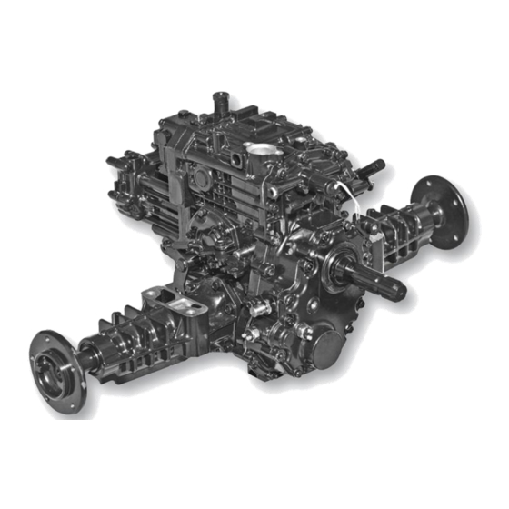
- Page 7 K92 Transmission Component Location Oil Port (Fill Tube not Shown) Main Transmission Case PTO Brake Cover Forward/Reverse Control Valves PTO Pressure Test Port Charge Pump Control Arm Damper 4WD Assembly PTO Electrical (Optional) Engagement Solenoid Center Block Valve Motor Case Assembly...
-
Page 8: Control Arm And Damper Removal And Installation
Tuff Torq K92 Hydrostatic Transaxle Control Arm and Damper Removal and Installation Before beginning tear down clean work area thoroughly and cover workbench with clean paper. This is extremely impor-tant as just one grain of sand can cause damage to the Hy-drostatic Rotating Group in the Transaxle. -
Page 9: Charge Pump Disassembly And Assembly
Charge Pump Removal and Installation NOTE: Installation is done in the reverse order of removal. • Tighten (2) short cap screws (A) to 25 N•m (18 lb-ft). • Tighten long cap screw (Y) to 39 N•m (29 lb-ft). NOTE: Approximate capacity of hydrostatic power train is 7.5L (7.9 qt) for 2WD and 7.8L (8.2 qt) for 4WD and 9.0L (9.5 qt) for 4WD w/rear PTO. - Page 10 Tuff Torq K92 Hydrostatic Transaxle Charge Pump Disassembly and Assembly (continued) A - Cap Screw (2 used), M10 x 65 6. Check small orifice in reducing valve (S) spool for obstruction. B - Plug 7. Replace parts if necessary. C - O-ring 8.
-
Page 11: Pto Solenoid Valve
Directional Control Valves 3. Plunger pin must move freely. Removal and Installation: Internal valve must move freely when valve is shaken. 5. Make sure orifice and all passages are free of any obstruction. 6. Assemble parts. IMPORTANT: Avoid damage! The reverse control valve must be installed in the left port. - Page 12 Tuff Torq K92 Hydrostatic Transaxle Disconnect solenoid connector (F) from wiring harness. (Fig. 7) A - Wave Washer 2. Remove nut (A) and O-ring (B). (Fig. 8) B - Spool C - Sleeve D - O-ring E - Flats F - Solenoid Armature...
-
Page 13: Pto Brake Removal And Installation
PTO Relief Valve Disassembly, Inspection 9. Position solenoid coil wire leads (P) to the right and approximately 45° above horizontal. and Assembly IMPORTANT: Avoid damage! When tightening plastic nut be sure to tighten nut to exact specifications. Nut has a very low torque. Any overtightening will damage the armature coil. - Page 14 Tuff Torq K92 Hydrostatic Transaxle 1. Remove plug (B) to drain oil from transaxle. (Fig. 14) NOTE: If rear PTO is installed, remove necessary rear PTO components before rear transaxle cover removal. (See “Rear PTO Removal and Installation” on page 12.) Remove optional rear PTO (A), if installed.
- Page 15 PTO Brake Disassembly, Inspection and Assembly (Fig. 17) Transaxle Case Side Cover Fig. 17, PTO Brake Disassembly CAUTION: Avoid Injury! PTO brake cover is spring loaded. Remove cap screws evenly to release spring force. F - Stopper A - Collar, Brake Pin B - O-ring G - Spring, Inner C - Pin, PTO Brake...
-
Page 16: Pto Drive Train (Mid-Pto) Removal And Installation
Tuff Torq K92 Hydrostatic Transaxle L - O-ring NOTE: Remove necessary rear PTO components M - PTO Brake Shoe before rear transaxle cover removal. (See “Rear PTO Removal and Instal-lation” on page 14.) N - PTO Clutch Assembly Remove optional rear PTO (A), if installed. (See “Rear 1. - Page 17 PTO Drive Train (Mid-PTO) Removal and Installation (continued) 8. Inspect ball bearings and needle bearing for A - PTO Clutch Assembly smooth rotation. B - Snap Ring NOTE: Idler gear (N) and shaft (O) must be replaced C - Needle Bearing as a set.
-
Page 18: Pto Drive Train (Mid And Rear Pto) Removal And Installation
Tuff Torq K92 Hydrostatic Transaxle Installing: PTO Drive Train (Mid and Rear PTO) Remov-al and Installation If replaced, install new needle bearing (F) from inside case with bearing identification marks toward the inside of NOTE: Approximate capacity of hydrostatic power train the case. - Page 19 PTO Drive Train (Mid and Rear PTO) Removal and Installation (continued) Inspect gears and splines for missing or chipped teeth, wear or damage. Replace parts if necessary. Fig. 22, PTO Drive Train (Mid and Rear PTO) Disassembly A - PTO Clutch Assembly K - Spline Collar B - Snap Ring L - Snap Ring...
- Page 20 Tuff Torq K92 Hydrostatic Transaxle Installing: 1. Clean mating surfaces of rear case and transaxle Rear PTO Case case. Be sure threaded holes are clean. (Fig. 23) Mating Surface 2. Apply petroleum jelly to seal on shaft of PTO clutch as-sembly (E).
-
Page 21: Rear Pto Removal And Installation
Rear PTO Removal and Installation NOTE: Approximate capacity of hydrostatic power train is 9.0L (9.5 qt) for 4WD w/rear PTO. Removing: CAUTION: Avoid Injury! Allow transaxle to cool before drain-ing fluid. Hot fluid can cause serious burns Remove plug (AA) to drain oil from transaxle. (Fig. 25) Fig. - Page 22 Tuff Torq K92 Hydrostatic Transaxle 3. Remove shift collar (F) and shifter fork (N) assembly together. (Fig. 27) 7. With fork groove of shift collar away from case, install shifter fork and collar. Be sure arm of shifter NOTE: If shift collar replacement is necessary, the rear shaft (E) fits into slot of shifter fork.
- Page 23 Rear PTO Removal and Installation (continued) 13. Remove snap ring (L), idler gear (G), snap ring (H), press bearing (I), and press bearing (K) from shaft (J). Inspect all components for wear or damage, replace as neces-sary. (Fig. 35) NOTE: Recall writing/numbers on all outer bearing races, and install bearings in reverse order as removal.
-
Page 24: Rear Pto Assembly
Tuff Torq K92 Hydrostatic Transaxle Rear PTO Assembly Fig. 37, Rear PTO Disassembly A - Cap Screw P - Shaft B - Spring Q - Washer C - PTO Case R - Input Gear D - O-ring S - Bearing... - Page 25 Rear PTO Removal and Installation (continued) Installing: NOTE: Installation is done in the reverse order of diassembly. Additional information can be found by refering to the “Rear PTO Removal and Installation” removal section, starting on page 14. Clean mating surfaces of cover (AD) and gear case (C).
-
Page 26: Differential Lock Shaft Disassembly And Assembly
Tuff Torq K92 Hydrostatic Transaxle Differential Lock Shaft Disassembly and Assembly Fig. 38, Differential Lock Shaft Disassembly A - Snap Ring (2 used) H - Roll Pin B - Spring I - Shift Collar C - Sleeve (2 used) J - Cap Screw... -
Page 27: Differential (2Wd) Disassembly And Assembly
Differential (2WD) Disassembly and Assembly Fig. 39, Differential (2WD) Disassembly A - Ball Bearing N - Differential Lock Collar B - Bevel Input Gear O - Left Ball Bearing C - Final Pinion Shaft 1. Use a puller to remove left ball bearing from differential holder. -
Page 28: Differential (4Wd) Disassembly And Assembly
Tuff Torq K92 Hydrostatic Transaxle 7. Inspect final gear (F) for worn or damaged teeth. (Fig. 39) 10. Install final gear on differential holder and carrier with the deeper offset of gear center away from the 8. Inspect ball bearings (A and D) for smooth rotation. -
Page 29: Pto Clutch Disassembly, Inspection And Assembly
Differential (4WD) Disassembly and Assembly (continued) NOTE: Final pinion shaft (C) and final gear (M) must 1. Use a puller to remove ball bearings (E) from differential holders (F and N). (Fig. 40) be re-placed as a set. Bevel input gear (B) and bevel input pinion (not shown) must be replaced as a set. - Page 30 Tuff Torq K92 Hydrostatic Transaxle A - Ball Bearing B - Snap Ring C - Clutch Shaft D - Needle Bearing E - Washer F - O-ring G - Piston H - Spring I - Washer J - Snap Ring...
-
Page 31: Wd Output Disassembly And Assembly
4WD Output Disassembly and Assembly 1. Drain transaxle. Remove the first press bearing (E), gear (Y), washer (Z), and gear (AA) from 4WD reduction shaft (X). Remove CAUTION: Avoid Injury! Allow transaxle to cool before 4WD reduction shaft (X), and the second press bearing drain-ing fluid. - Page 32 Tuff Torq K92 Hydrostatic Transaxle 12. Remove bolt (F) and keeper plate (AP) from the 16. Remove the bearing (E) from the 4WD output shaft (N). 4WD cover. 17. Carefully remove front shift collar (Q) from 4WD 13. Use drift to drive out spring pin (L) and roll pin ( M) output shaft.
- Page 33 4WD Output Disassembly and Assembly (continued) 21. Measure ID of pilot hole. If not within specifications, replace 4WD output shaft. 22. Inspect sleeve on 4WD output shaft (N) for wear. Re-place, as necessary. 23. Inspect splines on 4WD output shaft (N) and shift collar (Q) for damage.
- Page 34 Tuff Torq K92 Hydrostatic Transaxle 4WD Output Disassembly (continued) Fig. 52, 4WD Output Disassembly U - Bearing AG - Bolt V - Snap Ring AH - Bolt W - Collar AI - Washer X - Shaft Reduction 4WD AJ - Guide Pin...
-
Page 35: Hydrostatic Transmission 2Wd And 4Wd
Hydrostatic Transmission 2WD and 4WD Hydrostatic Transmission Motor Removal: Hydrostatic Transmission Removal: 1. Remove charge pump. (See “Charge Pump Removal and Installation” on page 2) IMPORTANT: Avoid damage! Do not drop or damage pump valve plate when removing center valve block assembly. Do not nick or scratch lapped or machined surfaces of the valve plates or cylinder block components. -
Page 36: Hydrostatic Transmission Motor Disassembly And Assembly (2Wd)
Tuff Torq K92 Hydrostatic Transaxle Hydrostatic Transmission Motor Disassembly and Assembly (2WD) Fig. 55, Hydrostatic Transmission Motor Disassembly (2WD) A - Cap Screw (2 S - Piston pieces) B - Seal Cap T - Gasket C - Snap Ring U - Thick Thrust Plate... - Page 37 Hydrostatic Transmission Motor Disassembly and Assembly (2WD) (continued) 3. Inspect rotating components: NOTE: Apply silicon sealant to outer edge of new seal cap. Install seal cap until cap is approximately 4 mm NOTE: Scoring is fine scratches or grooves cut into the highly (5/32 in.) be-low surface of motor case.
-
Page 38: Hydrostatic Transmission Motor Disassembly And Assembly (4Wd)
Tuff Torq K92 Hydrostatic Transaxle Hydrostatic Transmission Motor Disassembly and Assembly (4WD) Fig. 56, Hydrostatic Transmission Motor Disassembly (4WD) A - Cap Screw (2 R - Gasket pieces) B - Snap Ring S - Thick Thrust Plate C - Snap Ring... - Page 39 Hydrostatic Transmission Motor Disassembly and Assembly (4WD) (continued) 4. Inspect rotating components: 10. Remove snap ring (B) to remove shaft assembly compo-nents. NOTE: Scoring is fine scratches or grooves cut into the highly 11. Inspect bushing (U), thrust bearing (T) and shaft (G) machined surface.
-
Page 40: Center Valve Block Disassembly And Assembly
Tuff Torq K92 Hydrostatic Transaxle Center Valve Block Disassembly and Assembly Fig. 57, Center Valve Block Disassembly A - Holder K - Top Plug B - Spring L - O-ring C - Ball M - O-ring D - Push Pin... -
Page 41: Hydrostatic Transmission Motor Installation
Center Valve Block Disassembly and Assembly (continued) U - Center Valve Block 12. Inspect valve plate for grooves, scoring, discoloration or pitting. V - Needle Bearing (2 used) IMPORTANT: Avoid damage! Pump and motor valve W- Locating Pin (2 used) plates are not interchangeable. -
Page 42: Hydrostatic Pump Inspection
Tuff Torq K92 Hydrostatic Transaxle Hydrostatic Transmission Installation 1. Install gasket (C). (Fig. 59) IMPORTANT: Avoid damage! Do not drop or damage pump valve plate when removing center valve block assembly. Do Install center valve block (B) and motor assembly to not nick or scratch lapped or machined surfaces of the valve transaxle housing and secure with cap screws (A). -
Page 43: Transaxle Disassembly
Hydrostatic Pump Inspection (continued) 5. Remove PTO idler shaft assembly (C), snap ring (E), PTO gear (D) (or rear drive gear set). A - Washers B - Piston Spring (7 used) C - Snap Ring D - Cylinder Block E - Washer F - Spring G - Piston (7 used) H - Thick Thrust Plate... - Page 44 Tuff Torq K92 Hydrostatic Transaxle Transaxle Disassembly (continued) F - Input Shaft G - Snap Ring H - Snap Ring I - Ball Bearing J - Washer K - Snap Ring L - Snap Ring M - Washer Fig. 63, Transaxle Input Shaft Disassembly...
-
Page 45: Transaxle (Right Cover) Disassembly And Assembly
Transaxle (Right Cover) Disassembly and Assembly Fig. 66, Transaxle (Right Cover) Disassembly A - Swash Plate Bearing Q - Fulcrum Cap Screw B - Washer Remove nut (H), washer (I), and snap ring (F). (Fig. 66) C - Bushing 2. Pull swash plate from cover (E). D - Spring NOTE: Pump swash plate, bushing, and thin thrust E - Cover... -
Page 46: Inspection Of Transaxle Case
Tuff Torq K92 Hydrostatic Transaxle Inspection of Transaxle Case Fig. 69, PTO Brake Pin Port, Swash Plate Bearing, and Vent Cap Fig. 67, Front PTO Shaft Port 1. Remove front PTO shaft seal (B). (Fig. 67) 7. Inspect PTO brake pin sleeve (E) for scoring or damage. - Page 47 IMPORTANT: Avoid damage! Bearing and washer on top of differential assembly are loose. Do not drop or lose parts. Put fork of differential lock shaft into groove of collar on differential assembly. Install differential assembly and differential lock shaft together into transaxle case. 4.
-
Page 48: Rear Axle Assembly Removal And Installation
Tuff Torq K92 Hydrostatic Transaxle Install PTO brake shoe (D) and PTO clutch assembly (C). 13. Install axle housings. (Fig. 74) (See “PTO Brake Removal and Installation” on page 6.) 14. Install hydrostatic transmission and pump. (Fig. 72) 15. Install control arm damper. (See “Control Arm and 10. -
Page 49: Rear Axle Assembly - Disassembly And Assembly
Rear Axle Assembly - Disassembly and Assembly Fig. 76, Rear Axle Assembly Fig. 75, Rear Axle Disassembly 9. Install axle shaft assembly into axle housing using Remove large snap ring (B) from groove of axle housing a press. Press shaft only until a rapid increase in (G). -
Page 50: Brakes Removal And Installation
Tuff Torq K92 Hydrostatic Transaxle Brakes Removal and Installation Fig. 78, Brake Disassembly A - Snap Ring Q - Cam Lever R - Brake Cover B - Brake Actuator Plate S - Cap Screw C - Friction Plate D - Steel Plate E - Steel Ball Inspect components on brake cover (R). -
Page 51: Hydrostatic Flow Diagram Check Points
Hydrostatic Flow Diagram Check Points PTO Electrical Engagement Solenoid Fig. 79, Check Points Rear PTO Relief/Check/Tow Valve (Forward) Implement Relief Valve Check/Tow Valve (Reverse) Charge Pressure Control Valve Charge Pressure Test Port Anti–Cavitation Screen Anti–Cavitation Check Valve Pressure Reduction Valve Fig. - Page 52 Tuff Torq K92 Hydrostatic Transaxle...
-
Page 53: Troubleshooting Guides
Troubleshooting Guides Note: If your specific problem and/or solution is not listed below, consult a qualified Tuff Torq Disstibator. Hydrostatic Transmission Problems Machine will not move on its own power Erratic speed Free-wheeling linkage set for push or partially set ... - Page 54 Troubleshooting Guides Hydrostatic Transmission Problems (continued) PTO will not stay engaged (continued) Hydraulic noise (continued) Low charge pump output Pump or motor valve plates scored or worn PTO pressure control valve faulty Filter plugged or suction side air leak. Check filter, charge pump or case seal...
- Page 55 Troubleshooting Guides Transaxle Engagement Problems (continued) Differential lock will not engage Differential lock linkage is mis-adjusted. Differential lock collar, pin or differential carrier fail-ure Differential lock will not disengage Brakes are applied or mis-adjusted Differential lock linkage is mis-adjusted...
Need help?
Do you have a question about the K92 and is the answer not in the manual?
Questions and answers