
Related Manuals for Yamaha TS-S


Summary of Contents for Yamaha TS-S
- Page 1 YAMAHA SINGLE-AXIS ROBOT CONTROLLER TS Series User s Manual TS-S/TS-S2/TS-SH/TS-X/TS-P EPM0159204 Ver. 2.04 E119...
-
Page 3: Table Of Contents
2. Part names and functions 3 . System configuration 4. Installation and operation sequence Chapter 2 Installation and wiring 1. Installation method 1.1 Controller main body 1.1.1 TS-S TS-S2 TS-X TS-P 1.1.2 TS-SH 1.1.3 Installation screws 1.2 Regenerative unit (RGT) TS-X TS-P 1.3 Regenerative unit (RGU-2) - Page 4 7.1 Connecting the absolute battery 2-17 7.2 Replacing the absolute battery 2-18 8. Connecting the I/O signals 2-19 9 . Configuring an emergency stop circuit TS-S TS-S2 TS-SH 2-20 10. Configuring an emergency stop circuit TS-X TS-P 2-21 10.1 EXT connector signal names and functions 2-21 10.2 Wiring and connecting the EXT connector 2-23 10.3 Circuit details...
- Page 5 Chapter 5 Operation 1. Operation procedure 1.1 Overall operation timing chart 1.1.1 TS-S TS-S2 TS-SH 1.1.2 TS-X 1.1.3 TS-P 1.1.4 Communication check (field network) 1.2 Alarm occurrence and clearing 2. Origin search (return-to-origin) 2.1 Origin point detection method TS-S TS-S2 TS-X TS-SH...
- Page 6 CONTENTS TS Series User’s Manual 2.2 Origin point detection method TS-P 2.3 Origin point and coordinates relationship 5-10 2.4 Return-to-origin timing chart 5-10 3. Positioning operation 5-11 3.1 Basic operation 5-11 3.2 Positioning timing chart 5-14 3.3 Positioning merge operation 5-16 3.4 Push operation 5-18...
- Page 7 CONTENTS TS Series User’s Manual 7.5 Stop mode TS-S TS-S2 TS-SH 5-49 7.6 Magnetic pole position estimation TS-P 5-49 8. LED status indicators 5-50 9. TS-Monitor (Option) TS-X TS-P 5-51 9.1 Part names and functions 5-51 9.2 Opening or closing the TS-Monitor 5-51 9.3 Changing the screen...
- Page 8 CONTENTS TS Series User’s Manual 4 . Regenerative unit specifications 7-12 4.1 Dimensional outlines (RGT) 7-12 4.2 Dimensional outlines (RGU-2) 7-12 HT1 Operation Guide Introduction 1. What the HT1 does 1.1 HT1 panel layout 1.2 Connecting to the external safety circuit (HT1-D) 2.
- Page 9 CONTENTS TS Series User’s Manual 7. Monitor functions A-31 7.1 I/O monitor A-31 7.2 Status monitor A-32 7.3 Run monitor A-33 7.4 Alarm display A-34 7.5 Warning display A-34 7.6 Message display A-35 7.7 Alarm record display A-36 7.8 Information display A-37 8.
- Page 10 CONTENTS TS Series User’s Manual Point data writing 1 (M, P, S, AC, DC, Q, ZL, ZH, N, J, F, T) Point data writing 2 (P_, S_, AC_, DC_, Q_) B-10 Current position teaching (TEACH) B-11 Point data copying (COPY) B-11 Point data deleting (DEL) B-12...
- Page 11 CONTENTS TS Series User’s Manual 1.1 Installation 1.2 Wiring 2. Initial setting 2.1 Node number setting 2.2 Enable setting 3 . I/O interface specifications 3.1 Configuration 3.2 CC-Link type 3.3 EtherNet/IP type 4. Data setting and operation 4.1 Restrictions on gateway function 4.2 Data setting 4.3 Operation...
-
Page 13: Important Information Before Reading This Manual
Important information before reading this manual Contents Introduction Main functions About this manual Safety alert symbols and signal words CE marking 1. Safety standard 2. Safety measures 3. Robot safety measures 4. EMC countermeasure example Safety cautions Warranty... -
Page 15: Introduction
This manual explains four controller models, TS-S, TS-S2, TS-SH, TS-X, and TS-P. So, some functions or numeric values may vary depending on the controller model you are using. In this... -
Page 16: Main Functions
Main functions The following table shows the main functions of the controller. Function Explanation Reference Section Moves the robot slider to the specified position. There are 4 types of position operation: 1. Positioning operation Chapter 5 section 3, "Positioning operation". 2. -
Page 17: About This Manual
Although every effort was made to ensure that this manual content is accurate and complete, please contact YAMAHA if errors, misprints, or omissions are found. For information related to the robot unit, support software, and other optional devices, please refer to the... -
Page 18: Safety Alert Symbols And Signal Words
Safety aler t symbols and signal words The following safety alert symbols and signal words are used in this manual to describe safety concerns, handling precautions, prohibited or mandatory action and key points when using this product. Make sure you fully understand the meaning of each symbol and signal word and comply with the instructions. DANGER "DANGER"... -
Page 19: Ce Marking
1. Safety standard Cautions regarding compliance with EC Directives The YAMAHA robot (robot and controller) is not, in itself, a robot system. The YAMAHA robot is just one component that is incorporated into the customer's system (built-in equipment), and YAMAHA robots are in compliance with the EC Directives as they apply to built-in equipment. -
Page 20: Robot Safety Measures
Regarding EMC directives, the customer's final product (entire system) including the YAMAHA robot must provide the necessary countermeasures. We at YAMAHA determine a model for single units of YAMAHA robots (controller, robot, and peripheral device) and verify that it complies with the relevant standards of EMC directives. - Page 21 • Countermeasure components (1) Surge absorber Always install an external surge absorber to protect the controller from surge noise that may be generated by lightning. A recommended surge absorber is shown below. • Recommended surge absorber Manufacturer : SOSHIN ELECTRIC CO., LTD. Type No.
- Page 22 (2) Noise filter Always install an external noise filter to reduce conduction noise to the power supply line. A recommended noise filter is shown below. • Recommended noise filter Manufacturer : COSEL CO., LTD. Type No. : NAP-10-472 Dimensional outline (3.5) ±0.5 2-φ4.8...
-
Page 23: Safety Cautions
Failing to do so could result in serious accidents, including injury or death. (See section 9 "Configuring an emergency stop circuit" in Chapter 2. TS-S TS-S2 TS-SH ) (See section 10 "Configuring an emergency stop circuit" and section 12 "Safety circuit construction example" in Chapter 2. - Page 24 Tighten the fastening screws securely. Failing to do so could cause a poor connection, possibly resulting in malfunctions. Securely ground the power terminal block's ground terminal. TS-S TS-S2 TS-SH Failing to do so could result in malfunctions or breakdowns. Securely ground the power terminal block's ground terminal.
- Page 25 Immediately turn off the power if abnormal odors, sounds, or smoke are noticed during operation. Failing to do so could result in electrical shocks, fires, or equipment failure. Stop operation immediately, and contact your YAMAHA representative. • Maintenance and inspection Perform maintenance and inspection tasks only when instructions for doing so are provided by YAMAHA.
-
Page 26: Warranty
9. Pollution, salt damage, condensation; 10. Fires or natural disasters such as earthquakes, tsunamis, lightning strikes, wind and flood damage, etc; 11. Breakdown due to causes other than the above that are not the fault or responsibility of YAMAHA; The following cases are not covered under the warranty: 1. -
Page 27: Chapter 1 Overview
Chapter 1 Overview Contents 1. unpacking check 2. part names and functions 3. System configuration 4. Installation and operation sequence... -
Page 29: Unpacking Check
1 piece For NPN and PNP Absolute battery TS-X TS-SH 1 piece The accessories vary according to the shipment configuration. For details, contact YAMAHA or the sales outlet. Example of package contents Robot cable HT1 (Option) I/O cable Controller main body... -
Page 30: Part Names And Functions
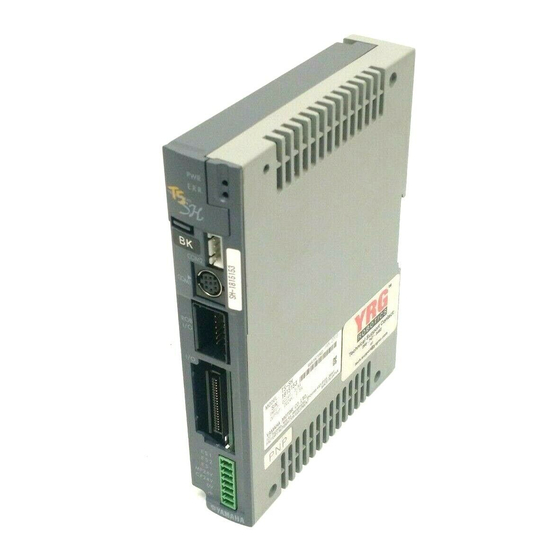
2. Par t names and functions This section explains the part names and functions of the controller. Part names and functions TS-S TS-S2 Controller • Robot I/O setting label TS-S2 (BK, SENSOR) • Status indicator lamps (PWR, ERR) • Communication connector 2 The controller status is indicated (COM2) by LED lamps. - Page 31 Green when lit. L ERR. LED Communication Red when lit. connector SD LED Orange when lit. RD LED Orange when lit. TS-S, TS-S2, TS-SH TS-X, TS-P 23102-M0-00 See Chapter 7 section 2.3, "CC-Link" for details of LED indicator lamp meanings.
- Page 32 DeviceNet MS LED Green/Red when lit. Communication connector NS LED Green/Red when lit. TS-S, TS-S2, TS-SH TS-X, TS-P 23103-M0-00 See Chapter 7 section 2.4, "DeviceNet" for details of LED indicator lamp meanings. EtherNet/IP NS LED Green/Red when lit. Link/Activity 1 LED EtherNet connection Green when lit.
-
Page 33: System Configuration
TS-X : FLIP-X series robot TS-P : PHASER series robot TS-S, TS-S2 : TRANSERVO series robot (Except for SG07) TS-SH : TRANSERVO series robot * For details about control target robots, refer to “1.2 List of controlled robots” in Chapter 7. -
Page 34: Installation And Operation Sequence
4. Installation and operation sequence The basic sequence from controller installation to actual operation is shown below. Installation and operation sequence Chapter 2 ”Installation and wiring” Installation · Cable and connector wiring and connection · Ground connection · Building the "emergency stop" circuit Power ON Chapter 3 "Data setting"... - Page 35 Connecting the absolute battery 2-17 Replacing the absolute battery 2-18 8. Connecting the I/o signals 2-19 9. Configuring an emergency stop circuit tS-S tS-S2 tS-Sh 2-20 10. Configuring an emergency stop circuit tS-X tS-p 2-21 10.1 EXt connector signal names and functions 2-21 10.2...
- Page 36 12. Safety circuit construction example 2-29 12.1 performance level 2-29 12.2 Circuit configuration examples tS-S tS-S2 tS-Sh 2-30 12.2.1 Category 3 2-30 12.2.2 Overview of circuit operation 2-31 12.3 Circuit configuration examples tS-X tS-p 2-32 12.3.1 Category 3 2-32 12.3.2 Overview of circuit operation...
-
Page 37: Installation Method
1. Installation method 1.1 Controller main body 1.1.1 TS-S TS-S2 TS-X TS-P Use the mounting screw holes to install the controller on a vertical wall in the manner shown below. Installation of controller main body TS-S, TS-S2 TS-X, TS-P 23201-M0-00... -
Page 38: Ts-Sh
After installed, reattach the cover in place. 23201-M5-00 1.1.3 Installation screws Use the following screw type for installation. Controller Model Mounting Area Thickness Hole Dia. Recommended Screw Recommended Tightening Torque TS-X, TS-P φ 5.4 1.5 N·m TS-S, TS-S2 φ 4.5 0.5 N·m φ 4.5 TS-SH 0.5 N·m... -
Page 39: Regenerative Unit (Rgt) Ts-X Ts-P
1.2 Regenerative unit (RGT) TS-X TS-P Use the back plate of the RGT to install it on a vertical wall in the manner shown below. Installation of RGT Back plate 23201-M1-00 Installation screws Use the following screw type for installation. Mounting Area Thickness Hole Dia. Recommended Screw Recommended Tightening Torque φ... -
Page 40: Installation Conditions
Install the controller on a vertical wall. Surrounding space Install the controller in a well ventilated location, with space on all sides of the controller (See the figure below.). Surrounding space TS-S, TS-S2, TS-SH TS-X, TS-P 20mm 20mm or more... -
Page 41: Wiring
3. Wiring 3.1 Power supply connection TS-S TS-S2 TS-SH Use the power connector supplied with the controller to connect the power supply. Power supply connector terminal names and functions Power supply connector Signal name Description Emergency stop contact 1 Emergency stop contact 2 Emergency stop ready signal (open: emergency stop) - Page 42 Considering generated heat amount Use the following tables as a guide to determine the control panel size, controller installation method, and cooling means. Model Generated heat amount (W) TS-S, TS-S2 TS-SH Signal Details • Emergency stop READY signal (ES-) This signal is used by the external safety circuit (e.g., safety enclosure, manual switch, etc.) in order to perform robot emergency stops.
-
Page 43: Power Supply Connection Ts-X Ts-P
3.2 Power supply connection TS-X TS-P Use the power connector supplied with the controller to connect the power supply. Power supply connector terminal names and functions Power supply connector (TS-X 205, 210, 220 TS-P 205, 210, 220 200VAC specs.) Signal Name Description Main power input 200 to 230VAC ±10%, 50/60Hz Control power input 200 to 230VAC ±10%, 50/60Hz Consumption current... - Page 44 Power supply connector wiring procedure CAutIoN • Disconnect the power connector from the controller before wiring. • Only one wire can be inserted into one wire hole of the power connector. • When inserting the wire into the terminal, use care to prevent the core wire from making contact with other conductive parts.
- Page 45 CAutIoN 1. leakage current is measured by a leak tester (hioki Electric 3283), with the low-pass filter (100hz) turned on. 2. When using multiple controllers, use the sum of the leakage currents from each controller. 3. Be sure that the controller is securely grounded. 4.
-
Page 46: Malfunction Prevention Measures Ts-X Ts-P
3.3 Malfunction prevention measures TS-X TS-P The following precautions must be taken to prevent noise related malfunctions. Installation of noise filter and ferrite core Install a noise filter and ferrite core near the controller. Do not bundle the noise filter's primary and secondary wires together. Installation of noise filter Bad example Noise filter's primary and secondary wires are bundled together. -
Page 47: Connecting The Robot
• Insert the cable plug into the connector until a clicking sound is heard (fully inserted). • Connect only the robot which is to be used. • Always grasp the connector body when plugging in and unplugging the cables. Connection method Connecting the robot TS-S TS-S2 TS-SH Controller Robot I/O connector... - Page 48 Robot I/O connector signal table TS-S TS-S2 TS-SH Pin No. Signal Name Description Resolver SIN input (+) Resolver SIN input (-) Resolver COS input (+) Resolver COS input (-) Resolver excitation output (+) Resolver excitation output (-) Frame ground BK+/ORG* Brake signal (+)/Origin sensor signal input...
-
Page 49: Connecting The Communication Unit
Press the cable's connector straight into the COM1 connector after aligning its arrow mark with the COM1 connector's triangular mark (on left side, as viewed when facing the unit). TS-S, TS-S2, TS-X, TS-P TS-SH Grasp the connector when inserting 23203-M0-00 2-13... - Page 50 "servo off" status is established at the robot. Communication device connection Communication connector 1 (COM1) Personal computer, etc. Communication cable TS-S, TS-S2, TS-X, TS-P TS-SH 23204-M0-00 Connecting a dummy connector The provided dummy connector must be plugged into the COM1 connector when operating the controller without connecting it to a communication unit.
-
Page 51: Connecting The Regenerative Unit Ts-X Ts-P
The regenerative unit absorbs regenerative current produced during motor speed reduction and radiates it as heat. A regenerative unit is required when operating certain robot models specified by YAMAHA or when handling large-inertia loads. Use the YAMAHA-specified dedicated cable to connect a regenerative unit to the controller. -
Page 52: Connecting The Rgu-2
6.2 Connecting the RGU-2 TS-P The following explains how to connect the RGU-2. CAutIoN • The power must be off when connecting the regenerative unit. • Insert the cable plug into the connector until a clicking sound is heard (fully inserted). • Install the regenerative unit in a well ventilated location with ample peripheral space (20mm or more). •... -
Page 53: Absolute Batter Y Ts-X Ts-Sh
7. Absolute batter y TS-X TS-SH The absolute battery is used to retain robot position data. 7.1 Connecting the absolute batter y To install the battery, first connect its cable to the BAT connector inside the panel, then install the battery. CAutIoN • Plug in and unplug the battery cable while grasping the connector body. •... -
Page 54: Replacing The Absolute Battery
7.2 Replacing the absolute batter y The absolute battery is a consumable item, and should be replaced when data backup problems occur (battery life expired). Although the battery life varies depending on the operating conditions, a general guideline is 8,000 hours (about one (1) year) (when left with the power turned off after connected to the controller). 3.6V 1650mAh Battery specification TS-X... -
Page 55: Connecting The I/O Signals
Two types of I/O signal connections (I/O and EXT I/O TS-X TS-P ) are provided for connection to external device such as a PLC. I/O wiring diagram Controller TS-S TS-S2 TS-SH I/O(NPN) 24V DC +COM I/O power + common POUT0 Point No. -
Page 56: Configuring An Emergency Stop Circuit Ts-S Ts-S2 Ts-Sh
9. Configuring an emergency stop circuit TS-S TS-S2 TS-SH The power supply connector provides functions for configuring safety circuits, including the robot. The following shows a power connector and host unit connection example. Emergency stop circuit Controller COM1 Handy Terminal External External "emergency stop" Status... -
Page 57: Ext Connector Signal Names And Functions
10. Configuring an emergency stop circuit TS-X TS-P The EXT connector provides functions for configuring safety circuits, including the robot. The following shows the EXT connector wiring and an example of connection with the host controller. 10.1 EXT connector signal names and functions The following explains the EXT connector signal names and functions. The EXT connector contains the robot's external safety circuit signals used for safe stops, and for the brake power supply terminal on robots equipped with brakes. - Page 58 • Emergency stop contacts 1, 2 (ES1, ES2) Description Signal Name When using Handy Terminal without an ENABLE switch When using Handy Terminal with an ENABLE switch Handy Terminal's emergency stop contact output 1 Connected to Handy Terminal's safety connector Pin No.14 Handy Terminal's emergency stop contact output 2 Connected to Handy Terminal's safety connector Pin No.15 Explanation When using a Handy Terminal which has no ENABLE switch, ES1 and ES2 serve as the Handy Terminal emergency stop...
-
Page 59: Wiring And Connecting The Ext Connector
10.2 Wiring and connecting the EXT connector This section explains the EXT connector wiring and connecting methods. EXT connector wiring method CAutIoN • Disconnect the EXT connector from the controller before wiring. • Only one wire can be inserted into one wire port of the EXT connector. • When inserting the wire into the terminal, use care to prevent the core wire from making contact with other conductive parts. -
Page 60: Circuit Details
10.3 Circuit details The following shows an EXT connector and host unit connection example. Safety circuit TS-X TS-P Controller COM1 Handy Terminal Status Internal Internal power 1 2 3 4 5 6 7 8 EXT connector External External External 24V "emergency stop"... -
Page 61: Connecting The I/O Unit
When purchasing the controller, a desired I/O unit can be selected from the NPN, PNP, CC-Link, DeviceNet and EtherNet/IP. The positioning or push operation can be controlled from the host unit, such as PLC through the I/O unit. Parallel I/O (NPN type and PNP type) Connecting a parallel I/O TS-S, TS-S2, TS-X, TS-P I/O connector TS-SH 23206-M0-00 CAutIoN •... - Page 62 NPN type I/O circuit details Input circuit +COM 24VDC 4.7kΩ Input Logic Internal circuit circuit -COM 23208-M0-00 Type : DC input (plus common type) Photo-coupler isolation format Load : 24VDC ± 10%, 5.1mA OFF voltage :19.6Vmin (1.0mA) ON voltage :4.9Vmax (4.0mA) Output circuit +COM Load Internal Logic...
- Page 63 CC-Link Terminal arrangement and connector specifications Name 5 4 3 2 1 23212-M0-00 Connection method TS-S, TS-S2, TS-X, TS-P TS-SH CC-Link connector Jump socket 23213-M0-00 Manufacturer part name Manufacturer name CC-LINK connector 35505-6000-B0M GF 3M Japan Corporation Jump socket 35715-L010-B00 AK...
- Page 64 DeviceNet Terminal array and connector specifications Name (Black) CAN_L (Blue) Shield CAN_H (White) (Red) 23214-M0-00 Connection method TS-S, TS-S2, TS-X, TS-P DeviceNet connector TS-SH 23215-M0-00 EtherNet/IP Number Name Terminal assignments and connector specifications RJ45 8-pin Modular connector (Controller side) 23217-M0-00 The customer must prepare an appropriate cable.
-
Page 65: Safety Circuit Construction Example
12. Safety circuit construction example This section describes category-specific safety circuit configuration examples using a Handy Terminal which has an ENABLE switch. Customers should install the appropriate safety measures for their system by referring to the safety circuits shown in circuit configuration examples, in order to use single-axis robots more safely. 12.1 Performance level To comply with the machinery directives, the "performance level (PL)"... -
Page 66: Circuit Configuration Examples Ts-S Ts-S2 Ts-Sh
12.2 Circuit configuration examples TS-S TS-S2 TS-SH Safety circuit configuration examples are shown below. Customers should install the appropriate safety measures for their system by referring to these safety circuit configuration examples in order to use the robots more safely. 12.2.1 Categor y 3 A safety circuit configuration example of category 3 is shown below. -
Page 67: Overview Of Circuit Operation
12.2.2 Over view of circuit operation This section describes an overview of the circuit operation for each safety circuit configuration example shown in the previous sections. The safety controller is programmed so that the operation is performed in the table below. Additionally, the safety controller is programmed so that it complies with the required standards other than the operations. -
Page 68: Circuit Configuration Examples Ts-X Ts-P
12.3 Circuit configuration examples TS-X TS-P Safety circuit configuration examples are shown below. Customers should install the appropriate safety measures for their system by referring to these safety circuit configuration examples in order to use the robots more safely. 12.3.1 Categor y 3 A safety circuit configuration example of category 3 is shown below. Category 3 safety circuit example TS-X TS-P Power wiring... -
Page 69: Overview Of Circuit Operation
12.3.2 Over view of circuit operation This section describes an overview of the circuit operation for each safety circuit configuration example shown in the previous sections. The safety controller is programmed so that the operation is performed in the table below. Additionally, the safety controller is programmed so that it complies with the required standards other than the operations. - Page 71 Chapter 3 Data setting Contents 1. Data overview overview Data system-of-units 2. point data "Standard setting" type "Custom setting" type 3. point data details 4. parameter data parameter list 4.1.1 RUN parameters 4.1.2 I/O parameters 3-10 4.1.3 Option parameters 3-10 4.1.4 Servo parameters 3-11 parameter details 3-11...
-
Page 73: Data Overview
1. Data over view 1.1 Over view Point data and parameter data settings must be specified in order to operate a robot from a TS series controller. Point data The point data used in positioning operations includes items such as the "RUN type", "Position", and "Speed", etc. Up to 255 points (P1 to P255) can be registered. -
Page 74: Point Data
2. Point data The point data includes items such as the "RUN type", "Position", and "Speed", etc. Point data item list P1 to P255 Item Description RUN type Specifies the positioning operation pattern. Position Specifies the positioning target position or movement amount. Speed Specifies the positioning speed. Accel. -
Page 75: Standard Setting" Type
1 to 100 Accel. 1 to 100 Decel. 1 to 100 TS-S, TS-S2, TS-SH : 1 to upper limit (depends on robot type) TS-S, TS-S2, TS-SH : Depends on robot type Push TS-X, TS-P : 1 to 100 TS-X, TS-P... -
Page 76: Custom Setting" Type
Accel. Depends on robot type Depends on robot type Decel. 1 to 100 TS-S, TS-S2, TS-SH : 1 to upper limit (depends on robot type) TS-S, TS-S2, TS-SH : Depends on robot type Push TS-X, TS-P : 1 to 100... -
Page 77: Point Data Details
3. Point data details This section explains the details of each point data item. RUN type Specifies the positioning operation pattern. For details on positioning operation, ABS (absolute position movement), and INC (relative position movement), see section 3, "Positioning operation", in Chapter 5. 1. - Page 78 Position Specifies the positioning target position or movement amount. • When the "RUN type" is specified as "ABS (absolute position) ..Target position. • When the "RUN type" is specified as "INC (relative position) ..Movement amount from current position. The illustration below shows a positioning example when a "Position = 100 (mm)"...
- Page 79 Zone (-) Zone (+) "Zone (-)" specifies the personal zone output (PZONE) range's lower limit (minus-direction limit). "Zone (+)" specifies the personal zone output (PZONE) range's upper limit (plus-direction limit). The personal zone output can be specified for each point data, and it switches ON when the robot's current position enters the personal zone.
- Page 80 For details about how to select the payload, see section 7.4, "Changing the payload", in Chapter 5. For details about stop mode (TS-S, TS-S2, and TS-SH only), see section 7.5, "Stop mode" in Chapter 5. For details about how to select the limitless rotation function, see section 3.9, "Limitless rotation function"...
-
Page 81: Parameter Data
4. Parameter data The 4 types of parameter data are shown below. Type Description These parameters are required for robot operation, and they include "soft limit" and "zone" RUN parameter settings. I/O parameter These parameters are for terminal assignment and I/O functions. These parameters are for optional settings (CC-Link and DeviceNet, etc.), and include the "node Option parameter No."... -
Page 82: I/O Parameters
• Speed switch Name Setting / Setting Range Units Default Restart Speed switch 0: Disable 1: Enable function Switched speed 1 to 100 • Limitless rotation function Name Setting / Setting Range Units Default Restart 0: Disable Limitless rotation 1: Enable function 2: Enable (shorter rotation) 4.1.2 I/O parameters • Terminal assignment Name... -
Page 83: Servo Parameters
*2. When "payload 2" (K78) is registered, this setting is converted to a value calculated by the prescribed formula. *3. Depending on the robot model, the point data system-of-units which appears in the User's Manual and support tools may differ from the actual system-of-units. • Stop mode TS-S TS-S2 TS-SH Name Setting / Setting Range... - Page 84 Settings Setting Value Description Push continuation after completion, with no failure judgment. Positioning after completion, with no failure judgment. Push continuation after completion, with failure judgment. Positioning after completion, with failure judgment. Setting Range Default Units Restart Push judgment time 1 to 60000 Function Specifies the time from "push start"...
- Page 85 • Return-to-origin related parameters Setting Range Default Units Restart Return-to-origin speed 0.01 to 100.00 Depends on robot type mm/s Function Specifies the return-to-origin movement speed. CAutIoN An alarm may occur during return-to-origin operation if the return-to-origin speed is set too high. Always set it to an appropriate value.
-
Page 86: I/O Parameters
NOTE Refer to section 3.8, "Speed switch function", in Chapter 5 for more details. Setting Range Default Units Restart Switched speed 1 to 100 Function Specifies the speed to be used after "Speed switch" has been performed. The maximum speed to be used by the speed switch function will be calculated by multiplying the current maximum speed by the value set in this parameter. - Page 87 Setting Range Default Units Restart POUT select 0 to 2 Required Function Specifies the output timing for the POUT0 to POUT7 point No. outputs. Settings Setting Value Description No output Output at positioning end (AFTER) Output at movement start (WITH) • Function selection related parameters Setting Range Default...
-
Page 88: Servo Parameters
Restart Max. payload accel. 2 Depends on robot type Function Specifies the maximum payload acceleration defined by the "Payload 2" (K78) parameter. This is a "read only" parameter. • Stop mode TS-S TS-S2 TS-SH Setting Range Default Units Restart K123 Stop mode setting... -
Page 89: Option Parameters
Settings Setting value Description Closed mode Open mode For details regarding the stop mode, see section 7.5, "Stop mode", in Chapter 5. Setting Range Default Units Restart K124 Stop mode switching time 0 to 5000 Function Specifies the time to wait before shifting to the stop mode after positioning is completed. Setting Range Default Units... -
Page 90: Devicenet
4.2.6 DeviceNet Setting Range Default Units Restart DeviceNet node 0 to 63 Required Function Specifies the DeviceNet communication node. Setting Range Default Units Restart DeviceNet speed 0 to 2 Required Function Specifies the DeviceNet baud rate. Settings Setting Value Description 125Kbps 250Kbps 500Kbps... - Page 91 Chapter 4 I/O signal functions Contents 1. I/o specifications NpN and pNp type CC-link type DeviceNet type EtherNet/Ip type 2. I/o signal list 3. I/o signal details Input signal details output signal details...
-
Page 93: I/O Specifications
1. I/O specifications The TS series allows positioning and push operations to be controlled from a host unit such as a PLC, etc., by way of an I/O interface. The I/O specifications for the I/O interface are shown below. (Selected at the time of purchase.) I/O Specification Explanation... -
Page 94: Cc-Link Type
1.2 CC-Link type Operation occurs as a CC-Link remote device station, on a one-unit to one-station basis. NOTE "Station No." and "baud rate" settings must be specified in order for the TS series to be recognized as remote station in the CC-Link system. These settings can be specified in the support software (TS-Manager), or from the HT1. - Page 95 Remote registers (word I/O) Remote commands can be executed by using the 4-word input and 4-word output remote registers. Inputs (Master Remote) Output (Remote Master) Address Signal Name Description Address Signal Name Description RWwn WIN0 Execution command RWrn WOUT0 Status RWwn+1 WIN1 RWrn+1 WOUT1 RWwn+2 WIN2...
-
Page 96: Devicenet Type
1.3 DeviceNet type Operate as slave stations, with each unit occupying 6 input and 6 output channels. NOTE MAC ID and baud rate settings are required in order for TS series to be properly recognized as a slave station in the DeviceNet system. These settings can be specified from the support software (TS-Manager), or from the HT1. (For the setting procedure, see section 5.3 "Setting Option parameters".) Remote I/O (bit I/O) Inputs (Master... -
Page 97: Ethernet/Ip Type
1.4 EtherNet/IP type Operates as slave stations (adapters), with each unit occupying 6 input and 6 output channels. NOTE IP address setting is required in order for TS series to be properly recognized as a slave station in the EtherNet/IP system. This setting can be specified from the support software (TS-Manager), or from the HT1. (For the setting procedure, see section 5.3 "Setting Option parameters"... -
Page 98: I/O Signal List
2. I/O signal list A list of the I/O signals is given below. For details regarding each signal, refer to section 3 "I/O signal details". Type Signal Name Meaning Description Point No. select • Specifies the point No. for the positioning operation. PIN0 to PIN7 0 to 7 •... -
Page 99: I/O Signal Details
3. I/O signal details This section explains the I/O signals in detail. 3.1 Input signal details PIN0 to PIN7 (Point No. Select) These inputs are read as 8-bit binary code Point Nos. when the START and TEACH commands are executed. • Input example PIN7 PIN0 Sum at ON Example Total = 41 (Point No.41) JOG+ / JOG- While this input is ON in the MANUAL mode, JOG movement to the specified direction's (+/-) soft limit occurs. - Page 100 START This input begins positioning to the point data specified by the PIN0 to PIN7 point No. select input. NOTE This input is enabled only when the MANUAL mode is OFF. TEACH This input sets (teaches) the current position at the point data position specified by PIN0 to PIN7 (point No. select). NOTE The TEACH input is only enabled when in the MANUAL mode (MANUAL = ON), with the /LOCK (interlock) input OFF.
-
Page 101: Output Signal Details
3.2 Output signal details POUT0 to POUT7 (point No. output) Outputs the current positioning operation's point No. as a binary output. When an alarm occurs, these signals output the alarm No. as a binary output. • Output example POUT7 POUT0 Sum at ON Example Total = 41 (Point No.41) OUT0 to OUT3 (control outputs) Performs the following outputs which have been assigned by the OUT0 Select (K21) to OUT3 Select (K24) I/O parameters. - Page 102 PZONE This signal switches ON during a positioning operation when the current position enters the point data's "Zone+" and "Zone-". After positioning ends, this signal remains enabled until the next positioning operation is executed. This signal is enabled only when assigned to one of the OUT0 to OUT3 control outputs. NEAR This signal switches ON during a positioning operation when the current position enters tolerance distance range versus the target position (the tolerance distance is specified by the point data's "Near Width"...
- Page 103 1.1.3 TS-P 1.1.4 Communication check (field network) Alarm occurrence and clearing 2. origin search (return-to-origin) origin point detection method tS-S tS-S2 tS-X tS-Sh origin point detection method tS-p origin point and coordinates relationship 5-10 Return-to-origin timing chart 5-10 3. positioning operation...
- Page 104 Soft limit function 5-47 zone output function 5-47 Alarm No. output function 5-48 Changing the payload 5-48 Stop mode tS-S tS-S2 tS-Sh 5-49 Magnetic pole position estimation tS-p 5-49 8. lED status indicators 5-50 9. tS-Monitor (option) tS-X tS-p 5-51...
-
Page 105: Operation Procedure
1.1 Overall operation timing chart The operation timing chart from "power ON" to the "positioning operation" is shown below. 1.1.1 TS-S TS-S2 TS-SH The TS-S, TS-S2 and TS-SH timing chart is shown below. From power ON to positioning operation TS-S TS-S2 TS-SH Control power (CP24V) -
Page 106: Ts-X
1.1.2 TS-X The following shows the timing chart of the TS-X controller. From power ON to positioning operation TS-X Control power (L1, N1) *4 *5 Initial processing Main power READY (MPRDY) Operation end (END) Emergency stop (E-STOP) Main power (L, N) Alarm (/ALM) Interlock (/LOCK) Servo ON (SERVO) -
Page 107: Ts-P
1.1.3 TS-P The following shows the timing chart of the TS-P controller. From power ON to positioning operation TS-P Control power (L1, N1) *5 *6 Initial processing Main power READY (MPRDY) Operation end (END) Emergency stop (E-STOP) Main power (L, N) Alarm (/ALM) Interlock (/LOCK) Servo ON (SERVO) -
Page 108: Communication Check (Field Network)
1.1.4 Communication check (field network) In a field network, always check that the communication state is normal before starting operation. When using the host unit's communication status flag to monitor the communication state, allow a time delay of about 200ms after recognizing a normal state, and then start operation. If the time delay is short, the controller output information may not be read correctly, so the operation cannot start normally. -
Page 109: Alarm Occurrence And Clearing
1.2 Alarm occurrence and clearing The operation timing chart from "alarm occurrence" to "alarm clear" is shown below. "alarm occurrence" to "alarm clear" Point No. select Setting Setting (PIN0 to PIN7) Point No. output Alarm No. Alarm No. (POUT0 to POUT7) Error occurrence Error occurrence Alarm (/ALM) Reset (RESET) -
Page 110: Origin Search (Return-To-Origin)
For the robot with the incremental specifications, the return-to-origin of the robot is needed each time the control power is started. 2.1 Origin point detection method TS-S TS-S2 TS-X TS-SH The following methods are available to detect the origin point. Each detection method is set as follows: Origin Detection Method... -
Page 111: Origin Point Detection Method Ts-P
If you want to change the return-to-origin method, contact yAMAhA. An alarm may occur during return-to-origin operation if the return-to-origin speed is set too high. Always set it to an appropriate value. - Page 112 Sensor method Movement in the return-to-origin direction occurs when a return-to-origin begins, and movement stops when the sensor detects the origin point dog. A return-to-origin end status is then established. Sensor method Sensor detection Return-to-origin direction (K14) = 0 (CCW) Return-to-origin direction (K14) = 1 (CW) Sensor Sensor When sensor is...
- Page 113 If you want to change the return-to-origin method, contact yAMAhA. An alarm may occur during return-to-origin operation if the return-to-origin speed is set too high. Always set it to...
-
Page 114: Origin Point And Coordinates Relationship
2.3 Origin point and coordinates relationship Coordinates are determined in accordance with the return-to-origin direction. The opposite direction from the return-to-origin direction is the "plus" direction. This direction (coordinate) setting can be reversed by changing the K15 ("Origin Coordi.") parameter setting. Return-to-origin direction Origin coordinates (K15) Return-to-origin direction (K14) Standard Direction... -
Page 115: Positioning Operation
3. Positioning operation A positioning operation can be performed by creating the required point data ("RUN type", "Position", "Speed", "Accel.", data, etc.), specifying the desired Point Nos. at PIN0 to PIN7 (point No. select), and then executing the START command input. Positioning can be executed as absolute position movement (ABS), as relative position movement (INC), or by a "push"... - Page 116 Setting the "Speed", "Accel.", and "Decel." data 1.When using the "Standard setting" point type The "Speed" and "Accel." settings are specified as a percentage of the optimal positioning speed and acceleration values for each robot type, based on that robot's maximum speed and maximum payload acceleration values. The "Decel." is specified as a percentage of the "Accel." setting. Point type: Standard setting Speed Max.
- Page 117 Maximum payload acceleration and the payload The maximum payload acceleration varies according to the payload setting. The optimum "maximum payload acceleration" is determined based on the robot's registered payload weight. Two "maximum payload acceleration" settings can be selected by "flag" acceleration selection. Maximum payload acceleration and the payload Max.
-
Page 118: Positioning Timing Chart
Acceleration S-cur ve The TS series features an S-curve function (standard item) to ensure smooth acceleration/deceleration. This results in a maximum acceleration which is 1.4 times that of a trapezoidal acceleration/deceleration format. Acceleration S-curve Speed Max. accel. Time 23512-M0-00 3.2 Positioning timing chart The timing chart for positioning operations is shown below. - Page 119 Point No. outputs An answer-back for the point Nos. used in the positioning operation occurs at the POUT0 to POUT7 point No. outputs. This output can be set to occur "WITH" (at movement start), or "AFTER" (at positioning end) by the K25 (POUT select) I/O parameter.
-
Page 120: Positioning Merge Operation
3.3 Positioning merge operation The positioning movement speed can be changed while in progress by performing positioning in the merge operation mode. The figure below shows an example of the following merge operation: "operation 1 (P1 positioning) operation 2 (P2 positioning) operation 3 (P3 positioning). Merge operation example Speed Operation 3... - Page 121 A period of time required to reach the merge destination speed is insufficient. Positioning merge operation A period of time required to reach the merge destination speed is insufficient. Speed Desirable acceleration Time Operation 2 Operation 1 23518-M0-00 CAutIoN In the example shown above, a sufficient period of time required for the acceleration or deceleration during operation cannot be taken, causing the robot operation to malfunction.
-
Page 122: Push Operation
3.4 Push operation A push operation is performed at the positioning operation. During the push operation, the torque is limited in accordance with the push force being used, allowing workpieces to be grasped and press-fit. Push operation example Speed Torque limit zone Speed Target position Time... - Page 123 Push judgment time This setting is used as the reference for "operation end" judgments at push operations. The "operation end judgment" is made when the time during which the torque level is at the push force reaches the K5 (push judgment time) RUN parameter setting.
-
Page 124: Deceleration Push Operation
3.5 Deceleration push operation Deceleration ends at the position set as the "Near width" value (distance) short of the target position, and the push operation then begins in accordance with the K6 (push speed) RUN parameter setting. Deceleration push operation Speed Torque limit zone Speed Deceleration ends when the "near width"... -
Page 125: Continuous Operation
3.6 Continuous operation "Continuous operation" refers to consecutive positioning operations which occur in response to an initial START command input. When one positioning operation ends, and the "Timer" specified delay (wait) time elapses, the next positioning operation begins for the "Jump" specified point No. Operation ends when there are no more "Jump"... -
Page 126: Output Function
3.7 Output function During positioning operations, individual operation speeds and position information are transmitted to the host unit by the outputs shown below. Output function Speed Speed Accel. Decel. Movement-in-progress output level (K12) Target position Zone - Zone + Position Near width Movement-in-progress output (MOVE) Personal zone... -
Page 127: Speed Switch Function
3.8 Speed switch function The overall positioning operation speed can be switched between two levels from the host equipment by using the speed switch input (SPD). Assigning method When you set the "Speed switch function" (K17) to "Enable", the speed switch (SPD) will be assigned to JOG+ input. SPD will be ON at the same time as the selection of point number, and the positioning operation will be performed at the speed calculated by multiplying the current speed by the value specified at "Switched speed"... -
Page 128: Limitless Rotation Function
3.9 Limitless rotation function This limitless rotation function achieves the multi-rotation motion in the same direction. Use of the limitless rotation function makes it possible to support the index table using the rotary axis model. The limitless rotation provides three kinds of operation methods, normal rotation, reverse rotation, and shorter rotation. Setting procedure As "Limitless setting"... -
Page 129: Operation Examples
3.10 Operation examples Setting example 1 Movement between 2 points, standard setting Speed 100% Position (200mm) (500mm) 100% 23525-M0-00 RUN type Position [mm] Speed [%] Accel. [%] Decel. [%] Flag A: P1 P2 positioning occurs. B: Return to P1. Setting example 2 Movement between 2 points, custom setting Speed 500.00mm/s... - Page 130 Setting example 3 Positioning + pitch feed Speed 100% 100mm 100mm 100mm Position (0mm) (200mm) 100% 23527-M0-00 RUN type Position [mm] Speed [%] Accel. [%] Decel. [%] A: P1 P2 positioning occurs. B: Pitch feed corresponding to the P3 movement amount occurs. C: Return to P1.
- Page 131 Setting example 5 Workpiece push Speed 100% (100mm) Workpiece Position (0mm) (350mm) 100% 23529-M0-00 RUN type Position [mm] Speed [%] Accel. [%] Decel. [%] Push Force [%] INC Push A: P1 P2 positioning occurs. B: Push operation corresponding to the P3 movement amount occurs. C: Return to P1.
-
Page 132: Manual Mode
4. MANUAL mode In the MANUAL mode, JOG movement and position teaching, etc., can be performed from a host unit by using the optional Handy Terminal (HT1) or the TS-Manager support software. This section explains the MANUAL mode functions. 4.1 MANUAL mode timing chart MANUAL mode MANUAL mode (MANUAL) -
Page 133: Jog Movement
4.2 JOG movement When in the MANUAL mode ("MANUAL" ON), robot JOG movement in the specified direction is possible while the JOG+ / JOG- input is ON. When this input switches OFF, a deceleration stop occurs. JOG movement can be performed even if a return-to-origin has not been completed. JOG movement Speed Inching width... -
Page 134: Teach (Teaching)
4.3 TEACH (Teaching) When in the MANUAL mode ("MANUAL" ON) with "/LOCK" switched OFF, the current position can be written to the specified point No. at the leading edge of the TEACH input ON. NOTE The TEACH function is disabled if a return-to-origin has not yet been completed. Current position is written to the specified point No. -
Page 135: Remote Commands
5. Remote commands 5.1 Over view Remote commands use the field network's remote register area to read and write various types of information, and perform the positioning operation. CC-Link Inputs (Master Remote) Output (Remote Master) Address Signal Name Description Address Signal Name Description RWwn WIN0... - Page 136 Point data writing Command Command Option Command Response Name WIN0 WIN1 WIN2, WIN3 WOUT1 WOUT2, WOUT3 Operation type write 0200h Point No. Operation type Point No. Position write 0201h Point No. Position data Point No. Speed write 0202h Point No. Speed data Point No.
- Page 137 Parameter writing Command Command Option Command Response Name WIN0 WIN1 WIN2, WIN3 WOUT1 WOUT2, WOUT3 In-position (K3) write 0400h 0003h In-position data Push mode (K4) write 0400h 0004h Push mode Push judge time (K5) write 0400h 0005h Push judge time data Push speed (K6) write 0400h 0006h...
- Page 138 Special codes Command Command Option Command Response Name WIN0 WIN1 WIN2, WIN3 WOUT1 WOUT2, WOUT3 Status clear (no execution) 0000h Status clear (continuous query continuation) 8000h Command response clear 0F00h 0000h 00000000h Status Status Name Description WOUT0 Command ready 0000h Command execution is enabled.
-
Page 139: Timing Chart
5.3 Timing chart This section explains the remote command input/output timing charts using remote command execution flowcharts and examples. When executing a quer y [Example] Executing "current position" reading Command option 0000h 0000h 0000h 0000h 0000h (WIN1) 0000h 0000h 0000h 0100h 0100h Command (WIN0) 0000h 0200h 0000h... -
Page 140: Query
5.4 Quer y Reads information (current position and speed, etc.) related to the operation. Command Option Command Input WIN3 WIN2 WIN1 WIN0 Type 0100h Command Response Status Output WOUT3 WOUT2 WOUT1 WOUT0 Data 0200h NOTE The "Data" is output as 2-word, Little Endian data. Command type and response data Command Option Command Response... -
Page 141: Point Data Writing
5.5 Point data writing Point data is written. Command Option Command Input WIN3 WIN2 WIN1 WIN0 Data Point No. 02xxh Command Response Status Output WOUT3 WOUT2 WOUT1 WOUT0 Point No. (response) 0200h Commands and data Command Option Units Data Write Command (WIN0) Destination Point No. (WIN1) Data (WIN2, WIN3) Standard Setting Custom Setting 0200h... -
Page 142: Point Data Reading
5.6 Point data reading Point data is read. Command Option Command Input WIN3 WIN2 WIN1 WIN0 Point No. 03xxh Command Response Status Output WOUT3 WOUT2 WOUT1 WOUT0 Data Point No. (response) 0200h NOTE The "Data" is output as 2-word, Little Endian data. Commands and data Command Option Command Response... -
Page 143: Parameter Data Writing
5.7 Parameter data writing Parameter data is written. Command Option Command Input WIN3 WIN2 WIN1 WIN0 Data Parameter No. 0400h Command Response Status Output WOUT3 WOUT2 WOUT1 WOUT0 0200h Command type and data Command Option Command (WIN0) Unit Parameter No. (WIN1) Data (WIN2, WIN3) Other than TS-P : 0.01mm 0003h In-position (K3) -
Page 144: Parameter Data Reading
5.8 Parameter data reading Parameter data is read. Command Option Command Input WIN3 WIN2 WIN1 WIN0 Parameter No. 0500h Command Response Status Output WOUT3 WOUT2 WOUT1 WOUT0 Data 0200h Command type and response data Command Option Command Response Command (WIN0) Unit Parameter No. (WIN1) Data (WOUT2, WOUT3) Other than TS-P : 0.01mm 0003h... -
Page 145: Continuous Query
5.9 Continuous quer y This function outputs operation information such as the current position and speed, etc., in a continuous manner. Command Option Command Input WIN3 WIN2 WIN1 WIN0 Type 8100h Command Response Status Output WOUT3 WOUT2 WOUT1 WOUT0 Data 0200h CAutIoN output occurs as 2-word, little Endian data. -
Page 146: Positioning Operation
5.10 Positioning operation There are two kinds of positioning operations available, "data designation type 1" that performs the operation by specifying the position data and "data designation type 2" that performs the operation by specifying the position and speed data. So, it is necessary to register the point data to the designation points beforehand. NOTE This function is available from controller’s software version Ver.1.11.125. - Page 147 Status Status Name Description WOUT0 Command ready 0000h Shows the command executable status. Receives the command to show that the positioning operation is in progress. Positioning operation in-progress (0100 + n) h The point number that is registered when entering the data is output to "n".
-
Page 148: Special Operations
5.11 Special operations Special operations are explained below. Brake release Releases the brake. Command Option Command Input WIN3 WIN2 WIN1 WIN0 0E00h Command Response Status Output WOUT3 WOUT2 WOUT1 WOUT0 0200h Brake ON Turns the brake on. Command Option Command Input WIN3 WIN2 WIN1 WIN0 0E01h... -
Page 149: Special Codes
5.12 Special codes This section explains the special codes. Status clear (no execution) The status is changed to the command ready (command executable status). Command Option Command Input WIN3 WIN2 WIN1 WIN0 0000h Command Response Status Output WOUT3 WOUT2 WOUT1 WOUT0 0000h Status clear (continuous quer y continuation) The status is changed to the command ready while continuing the data output to WOUT2, 3 by executing the continuous query. -
Page 150: Operation Modes
6. Operation modes In addition to I/O control from a host unit (PLC, etc.), the TS series also offers communication control from a personal computer (running the TS-Manager support software) and from Handy Terminal (HT1). In order to use these tools in a safe manner, the desired operation mode can be selected to enable exclusive operation. To select the operation mode, use the TS-Manager or HT1. -
Page 151: Other Functions
7. Other functions 7.1 Soft limit function Software imposed limits can be applied to the robot's range of motion in order to prevent interference with peripheral equipment. Robot movement is then restricted to target positions which are within the range specified by the soft limit function. The soft limit range can be set at the K1 (soft limit (-)) and K2 (soft limit (+)) RUN parameters. -
Page 152: Alarm No. Output Function
7.3 Alarm No. output function When an error alarm occurs, the alarm No. is output to the POUT0 to POUT7 point No. outputs. If multiple alarms have occurred, the highest priority alarm No. is output. The alarm No. output function can be enabled/ disabled by the K30 (Alarm No. -
Page 153: Stop Mode Ts-S Ts-S2 Ts-Sh
7.5 Stop mode TS-S TS-S2 TS-SH This switches the control during stop state after positioning operations. Use "Flag" for each point to switch the stop mode. Item Setting value Description Flag bit1=0 Closed mode Stop mode select Flag bit1=1 Open mode Closed mode This controller delivers high stop performance equivalent to servomotors by the vector control. -
Page 154: Led Status Indicators
8. LED status indicators Operation statuses are indicated by 2 types of LEDs located on the front face of the controller. The following table shows the LED statuses and their meanings. LED Name Color Status Meaning Control power shutoff Blue Blinking (at 0.5sec intervals) Servo OFF ON (constant ON) Servo ON... -
Page 155: Ts-Monitor (Option) Ts-X Ts-P
9. TS-Monitor (Option) TS-X TS-P This TS-Monitor is a LCD panel option prepared as an option of the controller. The TS Monitor displays various information on the screen, allowing you to check such information. Screen Contents INFORMATION screen Displays the controller, robot model name, or point type you are using. Displays the internal status of the servo and other devices, run mode, or current position. -
Page 156: Changing The Screen
9.3 Changing the screen Press the ▲ button or ▼ button on the TS-Monitor to change the TS-Monitor screen as follows. Changing the screen after normal startup Startup screen Transits after a certain period of time has elapsed. button INFORMATION CHECK screen screen button button... -
Page 157: Screen Configuration And Meaning
9.4 Screen configuration and meaning Startup screen When starting up the TS-Monitor, the following screen will appear. Startup screen TS-MONITOR VER. 1.00 Software version Booting up... 24501-M1-00 INFORMATION screen "INFORMATION" is displayed in the page name area at the uppermost portion on the INFORMATION screen. INFORMATION screen INFORMATION CONT :TS-... - Page 158 Simple status display Display Meaning Description Displays the servo status. Servo status ON: Servo on status, OFF: Servo off status Displays the emergency stop status. Emergency stop ON: Emergency stop status Displays the main power voltage drop. Main power failure ON: Main power voltage drop Return-to-origin Displays the return-to-origin completion status.
- Page 159 STATUS screen "STATUS" is displayed in the page name area at the uppermost portion on the STATUS screen. STATUS screen STATUS ON OFF SRV-S E-STOP ORGSEN P-BLK Status display TLM-S ORG-S : ON, : OFF MOVE WARN 24506-M1-00 Status display Display Meaning Description Displays the servo status.
- Page 160 Run type Display Meaning HOLD Servo is off or robot is stopping. ABS MERGE ABS merge operation INC MERGE INC merge operation ABS PUSH ABS push operation INC PUSH INC push operation ABS->PUSH ABS deceleration push operation INC->PUSH INC deceleration push operation Return-to-origin CHECK screen "CHECK"...
-
Page 161: Screen Color In Case Of Alarm
9.5 Screen color in case of alarm The screen color of the TS-Monitor changes according to the alarm occurrence status. The screen status and its meaning are descried in the table below. Status Meaning Blinks in blue (at intervals of 0.5 sec.). Servo is off and no error alarm occurs. Lit in blue. -
Page 162: Setup Screen
9.6 SETUP screen You can set the LCD contrast and backlight on time on the SETUP screen. To set these items, follow the steps below. Start up the SETUP screen. Step 2 "LCD SETUP" screen Turn on the power while holding down the ▼ button. - Page 163 Chapter 6 Troubleshooting Contents 1. Alarm groups 2. Alarm recording function 3. Alarm list 4. Alarms: possible causes and actions...
-
Page 165: Alarm Groups
1. Alarm groups Alarms on this controller are one of the following 5 groups. Group Description Message alarm Error messages involving data editing or operation commands sent as data. Operation alarm Alarm that appears when operation ends due to an error. Alarm that occurs due to internal causes. -
Page 166: Alarm Recording Function
2. Alarm recording function This function records and stores the error alarms (internal cause) as they occur, along with their alarm number and alarm conditions at that time. Up to 50 alarms can be stored. * This function does not store the "81: AC POWER DOWN" error alarm. Alarm description Item Description... -
Page 167: Alarm List
ORIGIN INCOMPLETE NO POINT DATA SOFTLIMIT OVER INTERLOCK STOP KEY PUSH MISTAKE ORG. MISTAKE SERIAL COMM. ERR. LIMITLESS ERROR TS-S, TS-S2, TS-P : × AC POWER DOWN Restart TS-X, TS-SH ENCODER ERROR Restart × × ABS. ENCODER ERR. TS-X TS-SH... -
Page 168: Alarms: Possible Causes And Actions
4. Alarms: Possible causes and actions Message alarms Message Meaning Possible Cause Action Attempt was made to enter data that Enter data within the DATA ERROR Data setting error exceeded the specified range. specified range. Data setting range Written data exceeded the specified Write data within the DATA RANGE OVER exceeded. - Page 169 OVERLOAD was exceeded. Supply the brake power Electromagnetic brake is not working. correctly. TS-X TS-S TS-S2 TS-X TS-SH Replace the brake. Wrong robot setting Make correct robot setting. Main power supply voltage exceeded Check the power supply. Overload detection level the specified range.
- Page 170 Message Meaning Possible Cause Action Connect the absolute Absolute battery voltage Absolute battery is disconnected. battery correctly. ABS. BATTERY ERR. dropped below the low TS-X TS-SH error detection level Absolute battery has worn out or Replace the absolute (2.5V). failed. battery.
- Page 171 Error alarms (external causes) Message Meaning Possible Cause Action External safety circuit functioned and Ensure safety and then emergency stop was activated. cancel the safety circuit. Emergency stop was EMERGENCY STOP activated. Emergency stop wiring is incomplete. Configure the safety Wiring is wrong. circuit correctly.
- Page 173 Chapter 7 Specifications Contents 1. Controller basic specifications Basic specifications 1.1.1 TS-S TS-S2 TS-SH 1.1.2 TS-X TS-P list of controlled robots Dimensional outlines 2. I/o inter face specifications CC-link DeviceNet EtherNet/Ip 3. tS-Monitor specifications tS-X tS-p 7-10 Basic specifications 7-10 Dimensional outlines (with tS-Monitor...
-
Page 175: Controller Basic Specifications
Protective structure *1. For "controlled robot" details, see section "1.2 List of controlled robots". *2. EtherNet/IP options cannot be installed into the TS-S. They are applicable to the models from TS-S2. *3. This value may vary depending on the model. -
Page 176: Ts-X Ts-P
1.1.2 TS-X TS-P 100V AC input 200V AC input Item TS-X105 TS-X110 TS-X205 TS-X210 TS-X220 TS-P105 TS-P110 TS-P205 TS-P210 TS-P220 TS-X: FLIP-X series Controllable robot TS-P: PHASER series Power capacity 400VA 600VA 400VA 600VA 1400VA Dimensions W58×H162×D131mm W70×H162×D131mm Weight Approx. 0.9kg Approx. -
Page 177: List Of Controlled Robots
1.2 List of controlled robots List Robot TS-X TS-P TS-S TS-S2 TS-SH Type Model SS04 SS05 SS05H SSC04 SSC05 SSC05H SG07 SR03 SR04 SR05 SRD03 SRD04 SRD05 STH04 STH06 RF02 RF03 RF04 BD04 BD05 BD07 T4LH T5LH F8LH F14H F17L B14H C4LH C8LH... - Page 178 Robot I/O setting and TRANSERVO series controllable robot TS-S2 TS-SH The robot I/O setting at shipment may vary depending on the robot model. Robot Robot I/O setting Return-to-origin method Model Detailed type SENSOR S, L, R SS04, SS05, SS05H Stroke-end method SB, LB, RB SSC04, SSC05, SSC05H Stroke-end method SG07 Stroke-end method...
-
Page 179: Dimensional Outlines
1.3 Dimensional outlines Dimensional outlines TS-S TS-S2 (70) φ4.5 (Units : mm) 23701-M3-00 Dimensional outlines TS-SH (70) φ4.5 (Units : mm) 23701-M5-00... - Page 180 Dimensional outlines TS-X TS-P (105/110/205/210) φ5.4 (90) EXT connector (Units : mm) 23701-M1-00 Dimensional outlines (220) TS-X TS-P φ5.4 (90) EXT connector (Units : mm) 23702-M1-00...
-
Page 181: I/O Interface Specifications
2. I/O interface specifications 2.1 Input 16 points, 24V DC ±10%, 5.1mA per point, positive common Output 16 points, 24V DC ±10%, 50mA per point, total 0.4A or less per 8 points, sink type 2.2 Input 16 points, 24V DC ±10%, 5.5mA per point, negative common Output 16 points, 24V DC ±10%, 50mA per point, total 0.4A or less per 8 points, source type 2.3... -
Page 182: Devicenet
2.4 DeviceNet DeviceNet specifications Item Description Volume1 Release2.0 Compatible DeviceNet Specs. Volume2 Release2.0 Vendor name Yamaha Motor Co.,Ltd. (ID=636) Device type Generic Device (Device No.0) Product code Product revision Max. network current consumption 40mA Physical layer insulation present/absent Present Support LED... -
Page 183: Ethernet/Ip
Description Volume1 : Common Industrial Protocol(CIP ) Edition 3.8 Compatible EtherNet/IP Specs. Volume2 : EtherNet/IP Adaptation Edition 1.9 Vendor name Yamaha Motor Co.,Ltd. (ID=636) Device type Generic Device Product code 12/14 (when the gateway function is enabled.) Product revision EtherNet interface... -
Page 184: Ts-P
3. TS-Monitor specifications TS-X TS-P 3.1 Basic specifications Item Specifications Effective display dimensions W40.546 × H25.63mm Screen display Graphic monochrome LCD Backlight Blue and red, 2-color LCD Contrast adjustment 5 steps Number of display dots 128 × 64 dots TS-X, TS-P105/110/205/210 with TS-Monitor W58 ×... - Page 185 Dimensional outlines (220) with TS-Monitor TS-X TS-P φ5.4 (83.5) 137.5 EXT connector (Units : mm) 23704-M1-00 7-11...
-
Page 186: Regenerative Unit Specifications
4. Regenerative unit specifications 4.1 Dimensional outlines (RGT) φ5.5 RGEN R2.75 (Units : mm) 23705-M1-00 4.2 Dimensional outlines (RGU-2) RGU-2 RGEN (Units : mm) 23701-M2-00 7-12... - Page 187 HT1 Operation Guide Contents Introduction 1. What the ht1 does ht1 panel layout Connecting to the external safety circuit (ht1-D) 2. Connecting or disconnecting the ht1 Connecting to the controller Disconnecting from the controller 3. Basic operations operation key layout and functions Screen configuration Starting to use the keys A-11...
- Page 188 7. Monitor functions A-31 I/o monitor A-31 Status monitor A-32 Run monitor A-33 Alarm display A-34 Warning display A-34 Message display A-35 Alarm record display A-36 Information display A-37 8. other functions A-38 operation mode A-38 Setting mode A-39 8.2.1 Changing the display language A-39 9.
-
Page 189: Introduction
Introduction This "HT1 Operation Guide" explains how to use the HT1 and HT1-D (with ENABLE switch) Handy Terminals that come with the TS series robot controller as an option. Before reading this section, read the precautions and descriptions stated in the "Controller Guide" (main part of this manual) to understand the point data and parameter data, as well as controller functions and usage. -
Page 190: What The Ht1 Does
1. What the HT1 does The HT1 Handy Terminal is provided as an option for the TS series controller. When connected to the controller, the HT1 allows you to perform the following operations and checks. HT1 tasks With the HT1 you can: Refer to: Set point data including "Run type", Position", "Speed", Data editing "Push"... -
Page 191: Ht1 Panel Layout
1.1 HT1 panel layout The HT1 consists of a LCD screen, data edit keys, run/stop keys, and emergency stop button as shown below. HT1 panel layout • Strap holder Attaching a short strap or necklace strap here prevents • Emergency stop button dropping the HT1 while operating Pressing this button during it or installing it onto equipment. -
Page 192: Connecting To The External Safety Circuit (Ht1-D
Rear view (HT1-D) • ENABLE switch (HT1-D only) This switch is used along with an external safety circuit. This switch turns off (opens) the circuit when pressed or released. Pressing this switch to mid-position enables the circuit. • Safety connector (HT1-D only) Use this connector along with the emergency stop or ENABLE switch to configure an external safety... -
Page 193: Connecting To The External Safety Circuit (Ht1-D)
1.2 Connecting to the external safety circuit (HT1-D) Using the safety connector on the HT1-D allows configuring an external safety circuit with the HT1-D emergency stop button or ENABLE switch. HT1-D wiring diagram HT1-D wiring diagram Emergency stop ENABLE HT1-D 1 2 3 4 5 6 7 8 14 15 HT1-D SAFETY HT1-D cable COM1... -
Page 194: Connecting Or Disconnecting The Ht1
2. Connecting or disconnecting the HT1 The HT1 can be connected or disconnected from the controller as needed regardless of whether controller power is on or off. CAutIoN • Do not modify the HT1 cable. Modified cables might cause communication errors or malfunctions. • When connecting the ht1 to the controller or disconnecting it from the controller, always grip it by the connector body itself. -
Page 195: Disconnecting From The Controller
2.2 Disconnecting from the controller The HT1 can be disconnected from the controller, regardless of whether the controller power is on or off. Pull the HT1 cable connector straight outwards from the COM1 connector on the controller. Disconnection Grip the connector body and pull it out. Controller 23A07-M0-00 CAutIoN... -
Page 196: Basic Operations
3. Basic operations The HT1 operation keys are only a minimum number of necessary keys, so HT1 operating procedures can easily be mastered even by first-time users. The HT1 operation keys are divided into two groups: data edit keys and run/stop keys. 3.1 Operation key layout and functions Operation key layout... -
Page 197: Screen Configuration
3.2 Screen configuration For position and zone parameters, a two decimal place number can be displayed and input in the TS-S, TS-S2, TS-SH and TS-X controllers. A three decimal place number can be input and displayed in the TS-P controller. Main menu screen On the main menu screen, the title "MENU"... - Page 198 "Run mode" display The currently selected "Run mode" is displayed as an abbreviation on the right of the status area. The meaning of each abbreviation is described below. "Run mode" display "Run mode" display Point teaching S=100% [01] 1. Run type 2. Position 100.00 3.
-
Page 199: Starting To Use The Keys
3.3 Starting to use the keys You can operate the HT1 while selecting the displayed menus (Refer to section 3.5, "Menu structure"). The following steps explain a basic HT1 key operation, showing the procedure for setting point data. CAutIoN Before editing data, always make sure that the robot is stopped. Editing data while the robot is moving may cause problems with the operation. -
Page 200: How To Enter Numbers
Step 4 Data edit screen • The point number can also be selected from the point number list that appears when you select Point number row "Point list" from the "Function" menu. (Refer to Point edit [01] section 4.4, "Displaying a list of point data".) •... - Page 201 Set the other point data items. Follow steps 5 to 7 to set the necessary data items. NOTE Repeat steps 3 to 7 when setting data items for other point numbers. After editing the data, press The cursor returns to the point number row. Pressing returns to the "Point"...
-
Page 202: How To Enter Numbers
3.4 How to enter numbers The HT1 has no number keys. Use to enter numbers. How to enter numbers 1. When in number edit mode, the edit cursor appears at the rightmost digit of the number. 2 3 . 4 2. To change the number at the specified digit (cursor position), press . -
Page 203: Menu Structure
3.5 Menu structure Menu structure Editing Operation Read only P1 to P255 (During editing) Point Edit 1. Run type Select number Teaching 2. Position Copy Menu [01] Point 3. Speed Delete this Operation FUNC Parameter Monitor 4. Accel. Delete all Run mode Connection 5. -
Page 204: Teaching Playback
4. Editing the point data The procedure for editing point data is described in the previous section 3.3, "Starting to use the keys", so please read it again. This section describes how to set the position for point data using point teaching, as well as how to copy or delete the point data you created. - Page 205 Specify the speed to move the Step 4 Specifying movement speed robot. Specify the speed as described below, on the "Function" menu that appears when you Point teaching S=100% [01] press FUNC 1. Run Function 1. Select "Change speed" and press 2.
-
Page 206: Direct Teaching
4.1.2 Direct teaching Direct teaching is basically the same as teaching playback, except that you move the robot by hand to a desired position in emergency stop. Open the "Point teaching" screen Step 4 Teaching current position and select the point number. Follow the instructions described in steps 1 to Point teaching S=100% [01]... -
Page 207: Copying Point Data
4.2 Copying point data This section describes how to copy created point data to another point data number. On the main menu screen, select Step 2 "Point edit" screen "Point". The "Point" menu screen appears. Point [01] Point edit Point teaching Move the cursor to "Point teaching"... -
Page 208: Deleting Point Data
4.3 Deleting point data This section describes how to delete created point data. CAutIoN Step 2 "Point edit" screen Deleted data cannot be restored, so be careful. Point [01] On the main menu screen, select Point edit Point teaching "Point". The "Point" menu screen appears. Move the cursor to "Point teaching"... -
Page 209: Displaying A List Of Point Data
4.4 Displaying a list of point data You can display a list of point data. You can also make entries on the data edit screen by selecting a point number from the displayed list. Step 2 On the main menu screen, select "Point edit" screen "Point". -
Page 210: Parameter Setting
5. Parameter setting The HT1 allows you to set parameters needed for robot operation. For detailed information and the setting range of each parameter, refer to the "Controller Guide", Chapter 3, section 4, "Parameter data". CAutIoN Before editing data, always make sure that the robot is stopped. Editing data while the robot is moving might cause problems with operation. -
Page 211: Setting I/O Parameters
5.2 Setting I/O parameters This section describes how to set an I/O parameter using "OUT0 select" (terminal assignment) as an example. Basically, other I/O parameters can also be set in the same manner. NOTE Power must be turned off and then back on to enable changes made to I/O parameters. -
Page 212: Setting Option Parameters
5.3 Setting Option parameters The following example shows the option parameters setting method when using CC-Link. The same setting method is used for DeviceNet. NOTE Power must be turned off and then back on to enable changes made to Option parameters. On the main menu screen, select Step 2 "Option parameter"... -
Page 213: Setting Servo Parameters
5.4 Setting Ser vo parameters This section describes how to set a Servo parameter using "Payload" as an example. Step 2 On the main menu screen, select "Servo parameter"screen "Parameter". Parameter [01] The "Parameter" menu screen opens showing Run parameter selectable parameter groups. I/O parameter Option parameter Move the cursor to "Servo... -
Page 214: Operating The Robot
6. Operating the robot 6.1 Turning the ser vo on or off This section describes how to check the servo status or how to turn the servo on or off. If the robot has a brake, the brake can also be engaged or released. On the main menu screen, select Step 2 "Servo status"screen "Operation"... -
Page 215: Origin Search (Return-To-Origin)
6.2 Origin search (return-to-origin) To find the robot origin position, use the following procedure after making sure that the servo is on. NOTE Step 2 "Origin Search" screen Origin search cannot be performed unless the servo is on. Operation [01] Servo status Origin search WARNING Reset... -
Page 216: Operating The Robot
6.3 Operating the robot This section describes how to position the robot using the HT1. WARNING Step 2 "Run" screen thE RoBot WIll NoW MovE, So uSE CAutIoN. Operation [01] On the main menu screen, select Servo status Origin search "Operation". Reset The "Operation"... - Page 217 Press to start operation. Step 5 Running screen The robot starts moving to the position specified by the point data. The message S=80% [01] "Running…" appears during operation. 1. Run type STOP If you want to stop the operation, press 2.
-
Page 218: Resetting An Alarm
6.4 Resetting an alarm If an alarm occurs during operation, the robot will immediately stop. After removing the cause of the alarm, the operation can be resumed by reset. On the "Operation" menu screen, Step 1 Alarm contents screen move the cursor to "Reset" and press Operation [01]... -
Page 219: Monitor Functions
7. Monitor functions The HT1 has the following monitor functions that display various types of information for checking operation and status. Monitor Function Description I/O monitor Displays the status of I/O signals exchanged with the host device. Status monitor Displays the status of servo, brake, emergency stop, etc. Run monitor Displays the current position, speed, run type, etc. -
Page 220: Status Monitor
7.2 Status monitor On the main menu screen, select Step 2 "Status monitor" screen "Monitor". The "Monitor" menu screen opens showing Monitor [01] selectable menu items. I/O monitor Status monitor Run monitor Move the cursor to "Status Alarm Warning monitor" and press Message The "Status monitor"... -
Page 221: Run Monitor
7.3 Run monitor On the main menu screen, select Step 2 "Run monitor" screen "Monitor". The "Monitor" menu screen opens showing Monitor [01] I/O monitor selectable menu items. Status monitor Run monitor Move the cursor to "Run monitor" Alarm Warning and press Message Alarm records The "Run monitor"... -
Page 222: Alarm Display
7.4 Alarm display Step 2 On the main menu screen, select "Alarm" screen "Monitor". The "Monitor" menu screen opens showing Monitor [01] I/O monitor selectable menu items. Status monitor Run monitor Move the cursor to "Alarm" and Alarm Warning press Message Alarm records The "Alarm"... -
Page 223: Message Display
7.6 Message display On the main menu screen, select Step 2 "Message" screen "Monitor". The "Monitor" menu screen opens showing Monitor [01] selectable menu items. I/O monitor Status monitor Run monitor Move the cursor to "Message" and Alarm Warning press Message The "Message"... -
Page 224: Alarm Record Display
7.7 Alarm record display On the main menu screen, select Step 2 "Alarm records" screen "Monitor". The "Monitor" menu screen opens showing Monitor [01] I/O monitor selectable menu items. Status monitor Run monitor Move the cursor to "Alarm records" Alarm Warning and press Message Alarm records The "Alarm records"... -
Page 225: Information Display
7.8 Information display The model names and specifications of the controller and robot being used can be displayed. On the main menu screen, select Step 2 "Information" screen "Monitor". Page 2 The "Monitor" menu screen opens showing selectable menu items. Monitor [01] Information Pressing... -
Page 226: Other Functions
8. Other functions 8.1 Operation mode When using the HT1, the operation mode can be set to any of the followings modes. The default setting is "Normal mode". Run mode HT1 operation I/O control from host device Description Normal mode All HT1 operations and host device I/O controls can be Permitted Permitted performed. -
Page 227: Setting Mode
8.2 Setting mode When you start the HT1 while holding down FUNC , the "Settings" screen appears as shown below. From this screen, you can change the LCD display language (Japanese/English) if needed. "Settings" screen Settings Serial port Language English Back light min. -
Page 228: Specifications
9. Specifications 9.1 Basic specifications Item Specifications Outer dimensions W88 × H191 × D45 mm (not including emergency stop button) : 260kg (without cable), 400g (including cable) Weight HT1-D : 300kg (without cable), 440g (including cable) Basic specifications Power 12V DC, 0.25A or less (supplied from controller) Cable length 3.5m Interface... -
Page 229: Ht1-D
9.2.2 HT1-D HT1-D 3-position ENABLE switch (Units: mm) Safety connector 23A14-M0-00 A-41... - Page 231 Communication Command Guide Contents Introduction 1. Communication specifications Communication parameter specifications Communication command specifications 2. Communication command lists 3. Communication command description Robot operation commands Positioning operation (START) Operation stop (STOP) Return-to-origin (ORG) JOG movement (JOG+, JOG-) Inching movement (INCH+, INCH-) Status change commands Servo status change (SRVO) Brake status change (BRK) Reset (RESET)
-
Page 233: Introduction
Introduction The TS series robot controller allows you to write the point data or operate the robot using a communication device, such as a personal computer through the RS-232C communication. This "Communication Command Guide" explains how to set the communication parameters necessary to perform the communication between the communication device and the TS series, and also explains the communication command specifications. -
Page 234: Communication Specifications
1. Communication specifications 1.1 Communication parameter specifications The communication parameters on the mating unit, such as personal computer must be set as follows. Refer to the relevant unit's operation manual for the setting procedure. Communication parameter specifications Parameter Setting Baudrate 38,400bps Data bit 8 bits Parity Stop bit 1 bit... -
Page 235: Communication Command Lists
2. Communication command lists Robot operation commands Command Format Command Description START @START<point number>[.<n>] Positioning operation STOP @STOP[.<n>] Operation stop @ORG[.<n>] Return-to-origin JOG+ @JOG+[.<n>] JOG movement (+ direction) JOG- @JOG-[.<n>] JOG movement (- direction) INCH+ @INCH+[.<n>] Inching movement (+ direction) INCH- @INCH-[.<n>] Inching movement (- direction) n: Node number Status change commands Command... - Page 236 Quer y commands Command Format Command Description @?M<point number>[.<n>] Operation type @?P<point number>[.<n>] Position @?S<point number>[.<n>] Speed @?AC<point number>[.<n>] Acceleration @?DC<point number>[.<n>] Deceleration @?Q<point number>[.<n>] Push Point data reading @?ZL<point number>[.<n>] Zone (-) @?ZH<point number>[.<n>] Zone (+) @?N<point number>[.<n>] Near width @?J<point number>[.<n>] Jump @?F<point number>[.<n>]...
-
Page 237: Communication Command Description
3. Communication command description 3.1 Robot operation commands The robot operation commands are intended to operate or stop the robot. Positioning operation (START) @START<point number>[.<node number>] c/r l/f Format @START<point number>[#P<position data>][.<node number>] c/r l/f Meaning Starts the positioning operation of specified point data. Function This command has the same function as the start (START) input. When #P<position data>... -
Page 238: Return-To-Origin (Org
Return-to-origin (ORG) Format @ORG[.<node number>] c/r l/f Meaning Performs the return-to-origin. Function This command has the same function as the return-to-origin (ORG) input. Setting <Node number> : 1 to 16 (This setting can be omitted when the same command is sent to all the controllers connected with the host device, as by daisy chain connection.) Communication example Transmission... -
Page 239: Inching Movement (Inch+, Inch
Inching movement (INCH+, INCH-) @INCH+[.<node number>] c/r l/f Format @INCH-[.<node number>] c/r l/f Meaning Performs the inching movement in the + or - direction. Function Performs the inching movement of the robot in a specified direction (+/-). NOTE • The inching width (amount) is set using "Inching width (K11)" of the RUN parameter. (See also Chapter 3, section 4.2 "Parameter details"... -
Page 240: Status Change Commands
3.2 Status change commands The status change commands are intended to change the servo or brake status. Ser vo status change (SRVO) Format @SRVO<1 or 0>[.<node number>] c/r l/f Meaning Changes the servo status. Function This command has the same function as the servo ON (SERVO) input. Setting <1 or 0>... -
Page 241: Edit Commands
However, when handling such data using the communication command, all of data are handled as integer values. For example, when the position data is "20 [mm]", the communication command at the TS-S, TS-S2, TS-SH, and TS-X would be "2000" (×10 ), and the communication command at the TS-P would be "20000"... -
Page 242: Point Data Writing 2 (P_, S_, Ac_, Dc_, Q_)
However, when handling such data using the communication command, all of data are handled as integer values. For example, when the position data is "20 [mm]", the communication command at the TS-S, TS-S2, TS-SH, and TS-X would be "2000" (×10 ), and the communication command at the TS-P would be "20000"... -
Page 243: Current Position Teaching (Teach
Setting <Point number> : 1 to 255 <Node number> : 1 to 16 (This setting can be omitted when the same command is sent to all the controllers connected with the host device, as by daisy chain connection.) Communication example Transmission Response @P_1.1=30000 c/r l/f Writes "30000"... -
Page 244: Point Data Deleting (Del
• Some parameter data may include the decimal point due to the specifications. However, when handling such data using the communication command, all of data are handled as integer values. For example, when K1 ((-) soft limit) is "20 [mm]", the communication command at the TS-S, TS-S2, TS-SH, and TS-X would be "2000" (×10 ), and the communication command at the TS-P would be "20000"... -
Page 245: Automatic Node Number Setting (Setid
Automatic node number setting (SETID) Format @SETID Meaning Sets node numbers for daisy-chained controllers. Function Sets the node numbers to the daisy-chained controllers from "1" in order of distance starting from the controller nearest to the host communication device. WARNING • THE MAXIMUM NUMBER Of CONTROLLERS THAT CAN BE DAISy-CHAINED IS 16. If 17 OR MORE CONTROLLERS ARE CoNNECtED, thEy MAy Not opERAtE pRopERly. -
Page 246: Query Commands
However, when handling such data using the communication command, all of data are handled as integer values. For example, when the position data is "20 [mm]", the communication command at the TS-S, TS-S2, TS-SH, and TS-X would be "2000" (×10 ), and the communication command at the TS-P would be "20000"... -
Page 247: Parameter Data Reading (?K
Some parameter data may include the decimal point due to the specifications. However, when handling such data using the communication command, all of data are handled as integer values. For example, when K1 ((-) soft limit) is "20 [mm]", the communication command at the TS-S, TS-S2, TS-SH, and TS-X would be "2000" (×10 ), and the communication command at the TS-P would be "20000"... -
Page 248: Status Data Reading (?D)
Status data reading (?D) Format @?D<status number>[.<node number>] c/r l/f Meaning Reads specified status information. Function Reads the status information, such as current position or speed. Setting <Status number> : 0 to 20 (See the table below.) <Node number> : 1 to 16 (This setting can be omitted when the same command is sent to all the controllers connected with the host device, as by daisy chain connection.) Data number and type of status information Number... -
Page 249: Input/Output Information Reading (?In, ?Inb, ?Out, ?Outb)
Input/output information reading (?IN, ?INB, ?OUT, ?OUTB) Input information @?IN<input number>[.<node number>] c/r l/f @?INB<input bit number>[.<node number>] c/r l/f Format Output information @?OUT<output number>[.<node number>] c/r l/f @?OUTB<output bit number>[.<node number>] c/r l/f Meaning Reads specified input/output information. Function Reads the information on specified input/output signal. The read-out results of the input/output information in decimal notation are returned. -
Page 250: Word Input/Output Information Reading (?Win, ?Wout)
Word input/output information reading (?WIN, ?WOUT) Input information @?WIN<word input number>[.<node number>]c/r l/f Format Output information @?WOUT<word output number>[.<node number>]c/r l/f Meaning Reads specified word input/output information. Function Reads the word input/output information. The read-out results of the word input/output information in decimal notation are returned. NOTE The word input/output is a data area to be used by the remote command. -
Page 251: Option Information Reading (?Opt, ?Optb)
Option information reading (?OPT, ?OPTB) @?OPT<option number>[.<node number>] c/r l/f Format @?OPTB<option bit number>[.<node number>] c/r l/f Meaning Reads specified option information. Function Reads the option information, such as zone output or emergency stop status. The read-out results of the option information in decimal notation are returned. Setting <Option number>... -
Page 252: Alarm/Warning Information Reading (?Alm, ?Warn)
Alarm/warning information reading (?ALM, ?WARN) @?ALM<alarm occurrence number>[.<node number>] c/r l/f Format @?WARN<warning occurrence number>[.<node number>] c/r l/f Meaning Reads the alarm/warning information currently occurring. Function Reads the alarm/warning information currently occurring. For details regarding the alarm and warning numbers and their contents, see Chapter 6 "Troubleshooting" of the Controller Guide. - Page 253 Daisy Chain Guide Contents Introduction 1. Installation and wiring Installation Wiring 2. Node number setting Automatic node number assignment function 2.1.1 When using the TS-Manager 2.1.2 When using the HT1 When controllers with same node number exist on network 2.2.1 When using the TS-Manager 2.2.2 When using the HT1 Switching the controllers...
-
Page 255: Introduction
Introduction The daisy chain function of the TS series controllers allows connection of up to 16 controllers in a daisy chain. Data settings such as point data and parameter data for any desired controller in the daisy chain can be set and the controller status monitored with a single computer or Handy Terminal. This section explains the daisy chain function when used with the support software TS-Manager or HT1. -
Page 256: Installation And Wiring
EMERGENCy Stop ButtoN oN thE hANDy tERMINAl. MAkE SuRE to INStAll EXtERNAl EMERGENCy Stop CIRCuItS BECAuSE othER CoNtRollERS CANNot BE StoppED WIth thE EMERGENCy Stop ButtoN oN thE hANDy tERMINAl. (REfER to SECtIoNS 9, "CoNfIGuRING AN EMERGENCy Stop CIRCuIt tS-S tS-S2 tS-Sh " AND 10, "CoNfIGuRING AN EMERGENCy Stop tS-X tS-p "... -
Page 257: Wiring
1.2 Wiring To connect controllers in a daisy chain, the YAMAHA-specified daisy chain connection cables must be used. The number of connection cables required is the number of controllers to be connected minus one. Also a computer with the TS-Manager software installed and one communication cable for connecting the computer with the controller are required. - Page 258 Connect the daisy chain cable to the controller. Insert the white connector of the daisy chain cable into the COM2 port on the controller to which you connected the communication cable. Connecting a daisy chain cable COM2 port TS-S, TS-S2, TS-X, TS-P Daisy chain cable TS-SH 23C03-M0-00 Connect the controllers to each other in a daisy chain.
-
Page 259: Node Number Setting
2. Node number setting 2.1 Automatic node number assignment function Daisy-chained controllers can be distinguished from each other by being assigned a different "node number". Node numbers can be set with the "Automatic node number assignment function" of the support software TS-Manager or with the HT1. They can also be set using the "Automatic node number setting (SETID)" communication command. - Page 260 Select the COM port. Select the COM port to which the communication cable is connected, and click the [OK] button. A confirmation message appears asking whether to start automatic node number assignment. "Automatic Node Number Assignment" screen Click. 24C03-M0-00 Start automatic node number assignment. Check the confirmation message and click the [OK] button to start automatic node number assignment.
-
Page 261: When Using The Ht1
Auto Node Set Step 3 Node number setting Connection [01] Cont. Cont. 01: *TS-X-20A Auto Node Set Set OK? Step 4 Assigned node numbers Connection [01] Cont. Cont. 01: *TS-X-20A TS-S TS-X-05A TS-S TS-X-05A TS-S TS-X-20A TS-S TS-X-05A TS-S TS-X-10A TS-P-20A TS-P-10A... -
Page 262: When Controllers With Same Node Number Exist On Network
2.2 When controllers with same node number exist on network 2.2.1 When using the TS-Manager If controllers having the same node number are connected in a daisy chain, a warning message appears when you try to connect a computer with the controllers. (See below.) In this case, perform automatic node number assignment by following the message. Node number overlap warning message 24C07-M0-00 Perform automatic node number assignment. -
Page 263: When Using The Ht1
[ ] on Connection [00] the upper right. Cont. Cont. Press to return to the menu screen. TS-X-20A TS-S TS-X-05A TS-S 24C39-M0-00 TS-X-05A TS-S TS-X-20A TS-S TS-X-05A TS-S... -
Page 264: Switching The Controllers
2.3 Switching the controllers You can check and edit the information of the daisy-chained controllers from the TS-Manager or from the HT1. 2.3.1 When using the TS-Manager From the "File" menu, select "New" – "Connection...". The "New Connection" dialog box then appears. You can also click the (New Connection) button on the toolbar. - Page 265 Select the controller. Select the controller you want to connect and then click the [OK] button. If not all controllers are displayed, click the [Research] button. NOTE If controllers having the same node number are found when "Research" is performed, a message screen appears asking whether to execute automatic node number assignment.
-
Page 266: Switching The Controllers Using The Ht1
Check that the selected controller Connection [01] is connected. Cont. Cont. 01: *TS-X-20A TS-S When the selected controller is connected, TS-X-05A TS-S an asterisk (*) appears to the left of the TS-X-05A TS-S controller name and the node number for... -
Page 267: Writing And Transferring Saved And Newly Made Data
3. Writing and transferring saved and newly made data This section describes how to write or transfer data from the computer to a daisy-chained controller. CAutIoN the daisy chain function cannot be used concurrently with the tS-Monitor (lCD monitor option) tS-X tS-p . If the backup data with the lCD setting enabled is written, the communication may not be performed properly. If there is a possibility that such data was written by mistake, perform automatic node number assignment again to disable the lCD setting. - Page 268 Select the controller where you want to transfer data. In the "Node Select" window, select the controller where you want to transfer data and click the [OK] button. If not all controllers are displayed, click the [Research] button. "Node Select" window Click.
- Page 269 Write the data. When a confirmation message appears asking whether to write the data to the selected controller, check the data name and the target controller, and click the [OK] button to start writing the data. If you want to cancel writing the data, click the [Cancel] button. Confirmation message Click.
-
Page 270: Transferring Data To Controller
3.2 Transferring data to controller Select the "PC to Controller…" command. Transferring data to controller Select. 24C19-M0-00 Select the file you want to transfer. When the "Data Transfer [PC to Controller]" window appears, click the […] button next to the "File Name" box. The "Open"... - Page 271 Select the COM port to connect to the controller. To transfer data to a currently connected controller, select the "COM port (in use)" (See below.). When you want to transfer data to a controller other than the currently connected one, either disconnect the connection or change the node number by performing "Switch Controller"...
- Page 272 If the robot name set in the data to be transferred to the controller does not match the robot name currently set in the controller, a confirmation message appears asking whether to continue data transfer. If you want to continue data transfer, click the [Yes] button. Transfer confirmation message due to robot name mismatch Click [Yes] to transfer data.
- Page 273 Another message appears asking whether to start data transfer. Check the data name and target controller, and click the [OK] button to start data transfer. To cancel data transfer, click the [Cancel] button. "Data transfer confirmation" message Click. 24C27-M0-00 Check that the data has been transferred. When the message appears stating the data transfer has been completed, click the [OK] button.
- Page 275 Gateway Function Guide Contents Introduction 1. Installation and wiring Installation Wiring 2. Initial setting Node number setting Enable setting 3. I/o inter face specifications Configuration CC-link type EtherNet/Ip type 4. Data setting and operation Restrictions on gateway function Data setting operation...
-
Page 277: Introduction
Introduction The gateway function of the TS series controller is that one controller incorporating the field network option plays a role of the gateway to collectively control multiple controllers through the daisy chain connection. Up to four controllers can be connected. CAutIoN •... -
Page 278: Installation
For the daisy chain connection among the controllers, use the daisy chain connection cable (300 mm) specified by YAMAHA. Daisy chain connection cables are required, the number of which is equivalent to (the number of controllers to be connected – 1). -
Page 279: Initial Setting
2. Initial setting This section describes the initial setting to enable the gateway function. 2.1 Node number setting When connecting the gateway, set node numbers for the controllers to be connected. Set node number “1” for the controller that becomes the top of the gateway, and then node numbers “2”, “3”, and “4” for subsequent controllers in order. -
Page 280: Configuration
3. I/O interface specifications This section describes the I/O interface specifications of the gateway function. 3.1 Configuration In the gateway connections, the first controller (gateway) with the field network option installed has I/O interfaces for this controller and daisy-chained controllers to distribute the input/output information to other daisy-chained controllers. -
Page 281: Cc-Link Type
3.2 CC-Link type This CC-Link type operates as a remote device station of the CC-Link and occupies four stations. CAutIoN Even when the number of connection units is less than 4, the number of stations to be occupied remains unchanged. the area without connection destinations becomes the reserved area. Remote input/output (bit input/output) Input (master →... -
Page 282: Ethernet/Ip Type
3.3 EtherNet/IP type This EtherNet/IP type operates as an EtherNet IP adapter, and both the input and output occupy 24 channels. CAutIoN Even when the number of connection units is less than 4, the number of channels to be occupied remains unchanged. -
Page 283: Data Setting And Operation
4. Data setting and operation This section describes the data setting, operation, and restrictions about the gateway function. 4.1 Restrictions on gateway function To use the gateway function, there are restrictions shown below. • Continuous quer y When the gateway function is enabled, the continuous query (0x8100) cannot be accepted. “02: Data error”... - Page 284 All rights reserved. No part of this publication may be reproduced in any form without the permission of YAMAHA MOTOR CO., LTD. Information furnished by YAMAHA in this manual is believed to be reliable. However, no responsibility is assumed for possible inaccuracies or omissions.
- Page 286 882 Soude, Nakaku, Hamamatsu, Shizuoka, 435-0054, Japan Tel. 81-53-460 - 6103 Fax. 81 - 53 - 460 - 6811 Robot manuals can be downloaded from our company website. Please use the following for more detailed information. http://global.yamaha-motor.com/business/robot/ YAMAHA MOTOR CO., LTD.