Table of Contents
Advertisement
SERVICE MANUAL
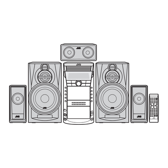
COMPACT COMPONENT SYSTEM
7 S ERVICE MANUAL
2007
MB620
DX-J35EE, DX-J35UX,DX-J35UG, DX-J35UN,
DX-J20EE, DX-J20UW,DX-J10EE
COPYRIGHT © 2007 Victor Company of Japan, Limited
Lead free solder used in the board (material : Sn-Ag-Cu, melting point : 219 Centigrade)
Lead free solder used in the board (material : Sn-Cu, melting point : 230 Centigrade)
1
PRECAUTION. . . . . . . . . . . . . . . . . . . . . . . . . . . . . . . . . . . . . . . . . . . . . . . . . . . . . . . . . . . . . . . . . . . . . . . . . 1-6
2
SPECIFIC SERVICE INSTRUCTIONS . . . . . . . . . . . . . . . . . . . . . . . . . . . . . . . . . . . . . . . . . . . . . . . . . . . . . . 1-9
3
DISASSEMBLY . . . . . . . . . . . . . . . . . . . . . . . . . . . . . . . . . . . . . . . . . . . . . . . . . . . . . . . . . . . . . . . . . . . . . . 1-10
4
ADJUSTMENT . . . . . . . . . . . . . . . . . . . . . . . . . . . . . . . . . . . . . . . . . . . . . . . . . . . . . . . . . . . . . . . . . . . . . . . 1-38
5
TROUBLESHOOTING . . . . . . . . . . . . . . . . . . . . . . . . . . . . . . . . . . . . . . . . . . . . . . . . . . . . . . . . . . . . . . . . . 1-40
SP-DXJ35S
SP-DXJ35F
SUPER VIDEO
SP-DXJ10
CA-DXJ10 SP-DXJ10
SUPER VIDEO
TABLE OF CONTENTS
COPYRIGHT © 2007 Victor Company of Japan, Limited
SP-DXJ35C
CA-DXJ35
SP-DXJ35F
SP-DXJ35S
SP-DXJ20W SP-DXJ20F
CA-DXJ20
SP-DXJ20F
No.MB620
2007/7
Advertisement
Table of Contents

Related Manuals for JVC DX-J35EE


Summary of Contents for JVC DX-J35EE
-
Page 1: Table Of Contents
SERVICE MANUAL COMPACT COMPONENT SYSTEM MB620 2007 7 S ERVICE MANUAL DX-J35EE, DX-J35UX,DX-J35UG, DX-J35UN, DX-J20EE, DX-J20UW,DX-J10EE SP-DXJ35C SP-DXJ35S SP-DXJ35F CA-DXJ35 SP-DXJ35F SP-DXJ35S SUPER VIDEO SP-DXJ10 CA-DXJ10 SP-DXJ10 SP-DXJ20W SP-DXJ20F CA-DXJ20 SP-DXJ20F SUPER VIDEO COPYRIGHT © 2007 Victor Company of Japan, Limited... - Page 2 SPECIFICATION DX-J35EE Ω Amplifier section Output Power FRONT SPEAKERS 100 W per channel min. RMS driven into 6 at 1 kHz with no more than 10% total harmonic distortion. 50 W per channel min. RMS driven into 6 Ω at 1 kHz with no SURROUND SPEAKERS more than 10% total harmonic distortion.
- Page 3 DX-J35UX,UG,UN Ω Amplifier section Output Power FRONT SPEAKERS 100 W per channel min. RMS driven into 6 at 1 kHz with no more than 10% total harmonic distortion. 50 W per channel min. RMS driven into 6 Ω at 1 kHz with no SURROUND SPEAKERS more than 10% total harmonic distortion.
- Page 4 DX-J20EE/DX-J10EE 100 W per channel min. RMS driven into 6 Ω at 1 kHz with no Amplifier section Output Power FRONT SPEAKERS more than 10% total harmonic distortion. 100 W min. RMS driven into 6 Ω at 63 Hz with no more than 10% SUBWOOFERS total harmonic distortion.
- Page 5 DX-J20UW Ω Amplifier section Output Power FRONT SPEAKERS 100 W per channel min. RMS driven into 6 at 1 kHz with no more than 10% total harmonic distortion. 100 W min. RMS driven into 6 Ω at 63 Hz with no more than SUBWOOFERS 10% total harmonic distortion.
-
Page 6: Precaution
SECTION 1 PRECAUTION Safety Precautions (1) This design of this product contains special hardware and voltmeter. many circuits and components specially for safety purpos- Move the resistor connection to each exposed metal es. For continued protection, no changes should be made part, particularly any exposed metal part having a return to the original design unless authorized in writing by the path to the chassis, and measure the AC voltage across... - Page 7 Preventing static electricity Electrostatic discharge (ESD), which occurs when static electricity stored in the body, fabric, etc. is discharged, can destroy the laser diode in the traverse unit (optical pickup). Take care to prevent this when performing repairs. 1.5.1 Grounding to prevent damage by static electricity Static electricity in the work area can destroy the optical pickup (laser diode) in devices such as laser products.
- Page 8 Important for laser products 1.CLASS 1 LASER PRODUCT 5.CAUTION : If safety switches malfunction, the laser is able to function. 2.CAUTION : (For U.S.A.) Visible and/or invisible class II laser radiation 6.CAUTION : Use of controls, adjustments or performance of when open.
-
Page 9: Specific Service Instructions
SECTION 2 SPECIFIC SERVICE INSTRUCTIONS This service manual does not describe SPECIFIC SERVICE INSTRUCTIONS. (No.MB620)1-9... -
Page 10: Disassembly
SECTION 3 DISASSEMBLY Main body 3.1.1 Removing the METAL COVER (See Fig.1, 2) (1) Remove the two screws A attaching the REAR COVER. (See Fig.1) (2) Remove the seven screws B attaching the METAL COV- ER. (See Fig.1) (3) Remove the four screws C attaching the both side of MET- AL COVER. - Page 11 3.1.2 Removing the DVD MECHANISM assembly (See Fig.3 to 5) (1) Disconnect the card wires from MICON BOARD assembly connected to connector CN701 CN801 of the DVD BOARD assembly. (See Fig.3) (2) Disconnect the card wire from AMP BOARD assembly con- nected to connector CN702 of the DVD BOARD assembly.
- Page 12 3.1.3 Removing the VIDEO BOARD assembly (See Fig.6, 7) (1) Disconnect the card wire from MICON BOARD assembly connected to connector CN931 of the VIDEO BOARD as- sembly. (See Fig.6) (2) Remove the three screws E attaching the VIDEO BOARD assembly.
- Page 13 3.1.4 Removing the MECHA CHASSIS (See Fig.8, 9) (1) Remove the two screws F attaching the MECHA CHAS- SIS. (See Fig.8) (2) Remove the two screws G attaching the both side of MECHA CHASSIS. (See Fig.9) Fig.8 Fig.9 (No.MB620)1-13...
- Page 14 3.1.5 Removing the FAN (See Fig 10, 11) (1) Disconnect the connector wire from FAN connected to con- nector CN630 of the MICON BOARD assembly. (See CN630 Fig.10) (2) Remove the one screw H attaching the FAN. (See Fig.11) Fig.10 Fig.11 1-14 (No.MB620)
-
Page 15: Sembly. (See Fig
3.1.6 Removing the TUNER PACK (See Fig.12, 13) (1) Disconnect the card wire from TUNER PACK connected to connector CN507 of the MICON BOARD assembly. (See CN507 Fig.12) (2) Remove the two screws J attaching the TUNER PACK. (See Fig.13) Fig.12 Fig.13 (No.MB620)1-15... - Page 16 3.1.7 Removing the REAR PANEL (See Fig.14) (1) Remove the four screws K attaching the HEAT SINK. (2) Remove the nine screws L attaching the REAR PANEL. Fig.14 1-16 (No.MB620)
- Page 17 3.1.8 Removing the AMP and SURROUND BOARD assembly (See Fig.15, 16) (1) Disconnect the card wires from MICON BOARD assembly connected to connector CN705 CN706 of the AMP CN760 CN706 CN705 BOARD assembly. (See Fig.15) (2) Disconnect the card wire from HEADPHONE BOARD as- sembly connected to connector CN760 of the MICON...
- Page 18 3.1.9 Removing the MICON BOARD assembly (See Fig.17) (1) Disconnect the power cord from connector CN410 of the CN500 CN501 MICON BOARD assembly. (2) Disconnect the card wire from FL BOARD assembly con- nected to connector CN500 of the MICON BOARD assem- bly.
- Page 19 3.1.11 Removing the SURROUND BOARD assembly (See Fig.20 to 22) (1) Disconnect the card wire from SURROUND BOARD as- sembly connected to connector CN711 CN712 of the AMP BOARD assembly. (See Fig.20) (2) Disconnect the card wire from AMP BOARD assembly con- nected to connector CN310 of the SURROUND BOARD...
- Page 20 3.1.12 Removing the B CASSETTE MECHANISM assembly (See Fig.23, 24) (1) Disconnect the connector wire from B CASSETTE MECH- ANISM assembly connected to connector CN200 of the A CN120 CN200 CASSETTE MECHANISM BOARD assembly. (See Fig.23) (2) Disconnect the card wire from B CASSETTE MECHANISM connected to connector CN120 of the A CASSETTE...
- Page 21 3.1.13 Removing the A CASSETTE MECHANISM assembly (See Fig.25) (1) Remove the four screws U attaching the A CASSETTE MECHANISM assembly. Fig.25 3.1.14 Removing the MIC BOARD assembly (See Fig.26) (1) Remove the volume knob. (2) Remove the two screws V attaching the MIC BOARD as- sembly.
-
Page 22: No.mb620)1
3.1.15 Removing the USB BOARD assembly (See Fig.27) (1) Remove the two screws W attaching the USB BOARD as- sembly. Fig.27 3.1.16 Removing the FRONT BOARD assembly (See Fig.28) (1) Remove the five screws X attaching the FUNCTION BOARD assembly. (2) Remove the five screws Y attaching the EJECT BOARD assembly. - Page 23 DVD changer mechanism assembly section Remove the DVD changer mechanism assembly from the main body. (See "Removing the DVD changer mechanism assembly".) 3.2.1 Removing the tray assemblies (See Figs.1 to 5) (1) From the top side of the main body, remove the two screws Top cover A from the top cover and release the two joints a on the both sides of the DVD changer mechanism assembly.
-
Page 24: No.mb620)1
Open det. lever Fig.3 Side(R) assembly Tray assemblies Fig.4 Tray assembly Fig.5 1-24 (No.MB620) - Page 25 3.2.2 Removing the DVD servo board (See Figs.6 to 8) Caution: Solder the short land sections d on the DVD pickup before dis- connecting the card wire extending from the DVD pickup. If you do not follow this instruction, the DVD pickup may be dam- DVD pickup aged.
- Page 26 3.2.4 Removing the motor board (See Figs.9 and 10) (1) From the top side of the DVD changer mechanism assem- bly, remove the two belts from the motor pulleys. (See Fig.9.) Note: Take care not to attach grease on the belt. Belt Belt (2) Remove the two screws D attaching the motors to the load-...
- Page 27 3.2.6 Removing the DVD traverse mechanism assembly (See Fig.11) • Remove the tray assemblies and DVD servo board. DVD changer mechanism assembly (1) From the bottom side of the DVD changer mechanism as- sembly, remove the three screws F attaching the DVD traverse mechanism assembly.
- Page 28 3.2.7 Removing the DVD pickup (See Figs.12 to 14) • Remove the tray assemblies, DVD servo board and DVD DVD traverse mechanism assembly traverse mechanism assembly. Feed bracket (1) From the top side of the DVD traverse mechanism assem- Thrust spring bly, release the lock of the connector on the DVD pickup Connector and disconnect the card wire in the direction of the arrow.
- Page 29 DVD pickup Rack arm Guide shaft Rack arm spring Fig.14 Connector DVD pickup Screw shaft gear Fig.15 (No.MB620)1-29...
- Page 30 3.2.9 Removing the spindle motor board (See Figs.16 and 17) • Remove the tray assemblies, DVD servo board and DVD DVD traverse mechanism assembly traverse mechanism assembly. (1) From the top side of the DVD traverse mechanism assem- Spindle motor board bly, remove the wires from the soldered sections r on the spindle motor board.
- Page 31 3.2.10 Removing the feed motor (See Figs.18 and 19) • Remove the tray assemblies and DVD traverse mechanism Feed bracket assembly. (1) From the top side of the DVD traverse mechanism assem- Thrust spring bly, remove the screw K attaching the feed bracket and re- move the feed bracket from the sections t.
- Page 32 3.2.11 Removing the side (L) and tray switch board (See Figs.20 to 22) • Remove the tray assemblies. SIde(L) (1) From the topside of the DVD changer mechanism assem- bly, remove the two screws M attaching the side (L). (See Fig.20.) (2) From the left side of the DVD changer mechanism assem- bly, disconnect the connector...
- Page 33 3.2.12 Removing the side (R) assembly (See Fig.23 to 27) • Remove the tray assemblies and DVD servo board. Elevator spring (1) From the inside of the side (R) assembly, release the two tabs aa of the gear cover and remove the gear cover out- ward.
- Page 34 3.2.13 Removing the lifter assembly (See Figs.28 to 32) • Remove the tray assemblies, DVD servo board, side (L) and Hook side (R) assembly. (1) From the top side of the DVD changer mechanism assem- bly, turn the gear 1 clockwise to move the lifter assembly upward.
- Page 35 3.2.14 Removing the sensor board and SV resistor (See Fig.33) • Remove the tray assemblies, side (L), side (R) assembly and Sensor board lifter assembly. (1) Remove the solders from the soldered sections aj on the sensor board and remove the wires. (2) Remove the two screws Q and take out the sensor board with the SV resistor.
- Page 36 3.2.15 Taking out the disc in the play mode (See Fig.34 to 37) Reference: Tray assembly Refer to "Removing the tray assemblies". (1) From the top side of the DVD changer mechanism assem- bly, remove the top cover. (2) Unlock the tray assemblies and draw out the tray assem- blies toward the front.
- Page 37 Tray stopper Main tray Sub tray Fig.36 Tray stopper Fig.37 (No.MB620)1-37...
-
Page 38: Adjustment
SECTION 4 ADJUSTMENT Attention in service of DVD section (1) When pickup, Flash ROM, DVD module board were changed, initialize EEPROM by all means. (2) When full initialization was executed, execute learning with a DVD test disk by all means. Test disc : VT-501, VT-502 Learning method : It is adjusted automatically by normal playback of a DVD test disc. - Page 39 DVD CHECK MODES a) Press MENU key again to enter CHECK MODE. (TEST MODE, MODE STATUS, CHECK MODE) i) During CHECK mode, press '1' key on REMOTE CONTROL to START PLAYBACK. ii) During CHECK mode, press '2' key on REMOTE CONTROL to perform SEARCH TNO+1 (2 seconds) Status: AA 00 cc cc jj jj iii) During CHECK mode, press '3' key on REMOTE CONTROL to perform SEARCH TNO-1...
-
Page 40: Troubleshooting
SECTION 5 TROUBLESHOOTING This service manual does not describe TROUBLESHOOTING. 1-40 (No.MB620) - Page 41 (No.MB620)1-41...
- Page 42 Victor company of Japan, Limited Audio/Video Systems category 10-1,1chome,Ohwatari-machi,Maebashi-city,371-8543,Japan (No.MB620) Printed in Japan...
- Page 43 SCHEMATIC DIAGRAMS COMPACT COMPONENT SYSTEM DX-J35EE,DX-J35UX,DX-J35UG DX-J35UN,DX-J20EE,DX-J20UW DX-J10EE CD-ROM No.SML200707 SP-DXJ35C SP-DXJ35S SP-DXJ35F CA-DXJ35 SP-DXJ35F SP-DXJ35S SUPER VIDEO SP-DXJ10 CA-DXJ10 SP-DXJ10 SP-DXJ20W SP-DXJ20F CA-DXJ20 SP-DXJ20F SUPER VIDEO Lead free solder used in the board (material : Sn-Ag-Cu, melting point : 219 Centigrade)
- Page 44 In regard with component parts appearing on the silk-screen printed side (parts side) of the PWB diagrams, the parts that are printed over with black such as the resistor ( ), diode ( ) and ICP ( ) or identified by the " " mark nearby are critical for safety.
-
Page 45: Block Diagram
Block diagram Surround & Center Amp section AOUT1, DAC1CS DVD servo and system control section RAOUTL/R Used for DX-J35 RAOUTL/R AOUT2, DAC2CS CAOUT, SWOUT SURR_LIN SURR_LOUT IC702.IC703 CAOUT A, B, C, D, E, F, RF+, LPC1, LPC2 SURR_RIN SURR_ROUT REAR/CENTER/SW DAC SWAOUT CTR_IN CTROUT... - Page 46 Standard schematic diagrams Primary section (for DX-J35) POWER SUPPLY BLOCK AC110V/127V/220V/230V-240V 50Hz/60Hz IC630 VOLTAGE SELECTOR LOCATION KIA278R09PI DVD5V D3.3V IC640 IC650 Q6601 KIA7806API KIA278R05PI KTC3203/OY/-T 110V 127V 220V 230-240V NI--->NO INSERT(NO USE) D6009 D6011 NOTES TW601 TW602 D6010 D6012 VOLTAGES ARE DC-MEASURED WITH A DIGITAL IC620 VOLTMETER OR OSCILLOSCOPE WITHOUT INPUT SIGNAL.
- Page 47 Primary section (except DX-J35) IC630 POWER SUPPLY BLOCK KIA278R09PI DVD5V AC110V/127V/220V/230V-240V 50Hz/60Hz D3.3V IC640 IC650 Q6601 VOLTAGE SELECTOR LOCATION PQ050RDC2SZF KIA7806API KTC3203/OY/-T 110V 127V 220V 230-240V D6009 D6011 TW601 TW602 D6010 D6012 IC620 NOTES KIA7809API VOLTAGES ARE DC-MEASURED WITH A DIGITAL VOLTMETER OR OSCILLOSCOPE WITHOUT INPUT SIGNAL.
- Page 48 Main section TO GVB10145-A2 (CN250) FROM DVD MODULE FMU-SB6-11M/-1M(J35) CN750 CN730 QGF1205C2-13 QGF1036C2-10 GVB10143-A1 FRONT MIX AMP *ONLY FOR J35 AGND AGND AGND B7009 *ONLY FOR J10/J20/J30 AGND DGND DGND B711 AHB2 CCT 10/63 LRMUTE C7112 R7112 R7113 0.1/50 SYSTEM MUTE C7346 C7511 R7210...
- Page 49 Micon section (for DX-J35) GVB10145-A1 TO GVB10145-A5 GVB10145-A2 CN902 TO DVD MECHA FROM ACM-W2 TO FMU-SB6 C2801 C2518 1/50 C2500 VREF MIX_OUT 1/50 10/50 R2570 CN502 R2600 R2513 C2522 CN501 QGF1036C2-28 R2601 CN503 CN504 QGF1205C2-21 QGF1205C2-15 MIX_NFIN QGF1036C2-05 ALC_TC ECHOVOL_IN C2517 C2601 C2600...
- Page 50 Micon section (except DX-J35) TO GVB10145-A5 GVB10145-A1 GVB10145-A2 CN902 TO DVD MECHA FROM ACM-W2 TO FMU-SB6 C2801 C2518 1/50 C2500 VREF MIX_OUT 1/50 10/50 R2570 CN502 C2522 R2601 R2600 R2513 CN501 CN503 QGF1036C2-28 QGF1205C2-21 CN504 MIX_NFIN QGF1205C2-15 QGF1036C2-05 ALC_TC ECHOVOL_IN C2517 C2601 C2600...
- Page 51 Surround amp section (only DX-J35) IC310 STK433-240A-E R3101 1/4W UNF R3102 1/4W UNF C3716 PGND C3616 C3516 PGND 100P/50 100P/50 100P/50 C3201 3P/50 R3202 C3401 3P/50 C3301 R3402 3P/50 C3402 R3302 5P/50 C3202 R3404 5P/50 C3302 Q3401 R3204 5P/50 CENTER VOL IC R3304 Q3201 Q3301...
- Page 52 Front section GVA10143-A3 FROM GVB10143-A1 CN760 FW970 R9710 QRJ146J-681X H/P MUTE FL100 1/4W Q9710 RT6N430C-X Q9711 RT6N430C-X Q9701 RT6N430C-X GVB10145-A4 Q9700 RT6N430C-X B9710 R9700 K9710 QQR0621-001Z QRJ146J-681X Q9720 C9711 RT1P140CC-X K9721 1/4W QQR0621-001Z BASS LED KARAOKE LED STANDBY LED C1008 B9721 K9700 C1010...
- Page 53 Cassette section GVA10149 QAL0966-001 (PB 1WAY) QAL0968-001 (R/P 2WAY) QAL0967-001 (PB 2WAY) R221 R220 R211 Q205 RECL R210 7.8V 6.0V 2.4K C217 Q200 RT1P430C-X 6.3V C219 0.01/50 C218 Q201 RT6N430C 4.7K 4.7K Q202 CN110 RT6N430C C220 R209 QGF1205F2-06 CN120 22/50 QGF1205C2-07 0.6V 1.2V...
- Page 54 DVD section 1/3 (for DX-J35) K354 48MHz NQR0022-002X C370 D1.2V REG. C328 0.01 DVDPWR 3.9V Cont D1.2V 1.2V P3.3V C302 47/4 IC302 MM1701CH-X CN301 QGA1002C1-06X for ICE D301 DGND RB521S-30-X CPURST EEPROM RESET R306 SCLK C564 DGND R307 SDATA DGND UCLK R353 (UCLK)
- Page 55 DVD section 2/3 (for DX-J35) SDRAM FLASH ROM IC505 IC509 SG32A90TFIR3 K4S641632K-UC75 EXADT15 0.4V 0.5V EXADR16 C560 3.3V EXADT14 0.7V 3.3V 2.8V 2.7V MDQ15 MDQ0 */BYTE DQ15 EXADT13 0.5V C551 3.3V VDDQ VSSQ EXADT12 0.7V 0.8V EXDT15 MDQ1 2.8V 2.7V MDQ14 DQ14 EXADT11...
- Page 56 DVD section 3/3 (for DX-J35) P3.3V DGND R859 R860 Q801 UN2113X IC801 MM1565AF-X KRA104S-X R891 Vout CN801 QGF1016F8-05W IC891 Cont C819 CN811 QGA2001F6-05X R819 R811 1/2W K811 R812 K812 1/2W LVA10543-601D (3/3) NOTES VOLTAGES ARE DC-MEASURED WITH A DIGITAL VOLT METER WITHOUT INPUT SIGNAL.
- Page 57 DVD section 1/3 (except DX-J35) K354 NQR0022-002X 48MHz C370 D1.2V REG. C328 0.01 DVDPWR 3.9V D1.2V Cont P3.3V 1.2V C302 47/4 IC302 MM1701CH-X CN301 QGA1002C1-06X for ICE D301 DGND RB521S-30-X CPURST RESET EEPROM R306 SCLK C564 DGND R307 SDATA DGND UCLK EXDT8 R353...
- Page 58 DVD section 2/3 (except DX-J35) SDRAM FLASH ROM IC505 IC509 SG32A90TFIR3 K4S641632K-UC75 EXADT15 0.4V 0.5V EXADR16 C560 3.3V EXADT14 0.7V 3.3V 2.8V 2.7V MDQ15 MDQ0 */BYTE DQ15 EXADT13 0.5V C551 3.3V VDDQ VSSQ EXADT12 0.7V 0.8V EXDT15 MDQ1 2.8V 2.7V MDQ14 DQ14 EXADT11...
- Page 59 DVD section 3/3 (except DX-J35) P3.3V DGND R859 R860 Q801 UN2113X IC801 MM1565AF-X KRA104S-X R891 Vout CN801 QGF1016F8-05W IC891 Cont C819 CN811 QGA2001F6-05X R819 R811 1/2W K811 R812 K812 1/2W LVA10543-611D (3/3) NOTES VOLTAGES ARE DC-MEASURED WITH A DIGITAL VOLT METER WITHOUT INPUT SIGNAL.
- Page 60 Loader section QVY0027-B14 WJM0331-001A-E QSW0923-001 WJM0330-002A-E LB1641 LB1641 TR3_CL TR2_CL QSW0854-002 TR4_CL TR1_CL TR5_CL M.TR_OP M.TR_OP TR5_CL TR5_CL TR4_CL TR4_CL POS_UP TR3_CL TR3_CL TR_OP TR2_CL TR2_CL POS_DOWN TR1_CL TR1_CL TR_CL 0.1/50 0.1/50 QSW0886-002 QRA0164-001 QRA0164-001 2-16...
-
Page 61: Printed Circuit Boards
Printed circuit boards (Eject board) S1201 Amp board Lead free solder used in the board (material : Sn-Ag-Cu, melting point : 219 Centigrade) Lead free solder used in the board (material : Sn-Cu, melting point : 230 Centigrade) R1208 R1209 R1207 R1206 (Amp board) - Page 62 Micon board Lead free solder used in the board (material : Sn-Ag-Cu, melting point : 219 Centigrade) Lead free solder used in the board (material : Sn-Cu, melting point : 230 Centigrade) (Micon board) D6602 D6701 R5066 D5100 CN507 R5450 CN630 R5065 R5079...
- Page 63 DVD board Lead free solder used in the board (material : Sn-Ag-Cu, melting point : 219 Centigrade) Lead free solder used in the board (material : Sn-Cu, melting point : 230 Centigrade) forward side CN452 CN453 C711 R107 IC705 K812 K811 Q101 R741...
- Page 64 Loader board Lead free solder used in the board (material : Sn-Ag-Cu, melting point : 219 Centigrade) Lead free solder used in the board (material : Sn-Cu, melting point : 230 Centigrade) (Motor board) (Tray switch board) (Switch board) (Sensor board) Cassette board Lead free solder used in the board (material : Sn-Ag-Cu, melting point : 219 Centigrade) Lead free solder used in the board (material : Sn-Cu, melting point : 230 Centigrade)
- Page 65 < M E M O >...
- Page 66 Victor Company of Japan, Limited Audio/Video Systems Category 10-1,1chome,Ohwatari-machi,Maebashi-city,371-8543,Japan Printed in Japan (No.MB620SCH)
-
Page 67: Parts List
DVD changer mechanism assembly and parts list (Block No.MT) (Exsept 35) 3-12 Electrical parts list (Block No.01~08) 3-28 Packing materials and accessories parts list (Block No.M3) (Only DX-J35EE) 3-30 Packing materials and accessories parts list (Block No.M4) (DX-J35UX,UG,UN) 3-32 Packing materials and accessories parts list (Block No.M5) -
Page 68: Exploded View Of General Assembly And Parts List
Exploded view of general assembly and parts list Block No. FL board MIC board Eject board Play board Function board USB board HP board... - Page 69 Only 35 Video board Except 35 85 88 Except EE Except 10,20 Only 35EE,35UX,35UG,35UN Except Only EE Amp board 20EE,20UW,10EE FL board Audio board Audio board Play board 35EE,35UX,35UG,35UN 20EE,20UW,10EE tion board Micon board...
- Page 70 General Assembly Block No. [M][1][M][M] Symbol No. Part No. Part Name Description Local GV10380-002A FRONT PANEL ASY 35EE,35UX,35UG,20EE,20UW,10EE GV10380-001A FRONT PANEL ASY 35UN GV20473-002A FL LENS 35EE,35UX,35UG,35UN GV20473-001A FL LENS 20EE,20UW,10EE GV31034-002A BUTTON LENS 35EE,35UX,35UG,35UN GV31034-001A BUTTON LENS 20EE,20UW,10EE GV31039-001A TRAY FITTING 1 GV31040-001A...
- Page 71 Symbol No. Part No. Part Name Description Local GV10370-009A REAR PANEL 20UW GV10370-022A REAR PANEL 10EE GV20334-001A REAR COVER QAU0492-001 TUNER GV31030-001A FAN BRACKET QAR0453-001 GV30349-026A SPACER QYSBSGY3008EA TAP SCREW M3 x 8mm QYSBSGY3008EA TAP SCREW M3 x 8mm(x4) QYSBSGY3008EA TAP SCREW M3 x 8mm(x2)
- Page 72 DVD mechanism assembly and parts list Block No. FXL-D20-11M Grease =JVG-31N =JVS-1003 =1401C < Back side > 7.0mm 0.2mm The parts without symbol number are not service.
- Page 73 DVD mechanism Block No. [M][J][M][M] Symbol No. Part No. Part Name Description Local LV22234-001A TM.CHASSIS LV22294-001A C.SPINDLE BASE QYSDST2005ZA TAP SCREW M2 x 5mm(x2) LV36791-001A C.G.S.HOLDER QYSDST2005ZA TAP SCREW M2 x 5mm LV44041-002A GUIDE SHAFT LV44479-001A BAR SPRING LV22236-001A FEED HOLDER QAR0165-001 FEED MOTOR...
- Page 74 DVD changer mechanism and parts list(Only DX-J35) FMU-SB6-1M Block No. Grease =JVG-31N =JVS-1003 CH5-BASE-1M The parts without symbol number are not service.
- Page 75 DVD changer mechanism(Only DX-J35) Block No. [M][K][M][M] Symbol No. Part No. Part Name Description Local LV10913-001A LOADER ASSY QVY0027-B14 S V RESISTOR QYSDST2004Z SCREW 2mm x 4mm QAR0164-001 MOTOR (x2) LV42340-001A MOTOR PULLEY (x2) LV41431-002A BELT (x2) QYSPSPU1725N SCREW 1.7mm x 2.5mm(x2) LV33965-004A LIFTER ASSY...
- Page 76 DVD changer assembly and parts list(Except DX-J35) FMU-SB6-11M Block No. Grease =JVG-31N =JVS-1003 CH5-BASE-1M The parts without symbol number are not service. 3-10...
- Page 77 DVD changer mechanism(Except DX-J35) Block No. [M][T][M][M] Symbol No. Part No. Part Name Description Local LV10913-004A LOADER ASSY QVY0027-B14 S V RESISTOR QYSDST2004ZA TAP SCREW M2 x 4mm QAR0164-001 MOTOR (x2) LV42340-001A MOTOR PULLEY (x2) LV41431-002A BELT (x2) QYSPSPU1725NA SCREW M1.7 x 2.5mm(x2) LV33965-004A...
-
Page 78: Electrical Parts List
Electrical parts list AMP board Symbol No. Part No. Part Name Description Local Block No. [0][1] D1003 SLR-343VC-T Symbol No. Part No. Part Name Description Local D3201 MA111-X SI DIODE 35EE,35UX, 35UG,35UN D3301 MA111-X SI DIODE 35EE,35UX, 35UG,35UN IC101 PT6324-HT D3401... - Page 79 Symbol No. Part No. Part Name Description Local Symbol No. Part No. Part Name Description Local C3604 QETN1HM-104Z E CAPACITOR 0.1uF 50V M 35EE,35UX, C7319 QFLC1HJ-103Z M CAPACITOR 0.01uF 50V J 20EE,20UW 35UG,35UN C7321 QFVF1HJ-274Z MF CAPACITOR 0.27uF 50V J C3605 QETN1HM-105Z E CAPACITOR...
- Page 80 Symbol No. Part No. Part Name Description Local Symbol No. Part No. Part Name Description Local C8218 QTE1E46-107Z E CAPACITOR 100uF 25V 20EE,20UW R3206 NRSA63J-473X MG RESISTOR 47kΩ 1/16W J 35EE,35UX, 35UG,35UN C8220 QEZ0863-106Z M CAPACITOR 10uF 35EE,35UX, 35UG,35UN, R3207 NRSA63J-104X...
- Page 81 Symbol No. Part No. Part Name Description Local Symbol No. Part No. Part Name Description Local R3807 NRSA63J-103X MG RESISTOR 10kΩ 1/16W J 35EE,35UX, R7440 NRSA63J-472X MG RESISTOR 4.7kΩ 1/16W J 35UG,35UN R7441 NRSA63J-102X MG RESISTOR 1kΩ 1/16W J R3808 NRSA63J-332X MG RESISTOR...
- Page 82 Symbol No. Part No. Part Name Description Local Symbol No. Part No. Part Name Description Local R7804 NRSA63J-0R0X MG RESISTOR 0Ω 1/16W J 35EE,35UX, L8250 QQLZ035-R39 COIL 0.39uH 20EE,20UW 35UG,35UN R7805 NRSA63J-0R0X MG RESISTOR 0Ω 1/16W J 20EE,20UW CN101 QGF1036F2-13 CONNECTOR...
- Page 83 Symbol No. Part No. Part Name Description Local Symbol No. Part No. Part Name Description Local S1305 QSW0683-001Z PUSH SW D6301 MTZJ13B-T2 Z DIODE S1306 QSW0683-001Z PUSH SW D6401 MTZJ6.2B-T2 Z DIODE S1307 QSW0683-001Z PUSH SW D6501 MTZJ6.2B-T2 Z DIODE S1308 QSW0683-001Z...
- Page 84 Symbol No. Part No. Part Name Description Local Symbol No. Part No. Part Name Description Local C6402 QETN1CM-107Z E CAPACITOR 100uF 16V M R5028 NRSA63J-102X MG RESISTOR 1kΩ 1/16W J C6502 QETN0JM-108Z E CAPACITOR 1000uF 6.3V M R5030 NRSA63J-102X MG RESISTOR 1kΩ...
- Page 85 Micon board(Except DX-J35) Symbol No. Part No. Part Name Description Local Block No. [0][3] R5431 NRSA63J-394X MG RESISTOR 390kΩ 1/16W J R5440 NRSA63J-0R0X MG RESISTOR 0Ω 1/16W J Symbol No. Part No. Part Name Description Local R5441 NRSA63J-394X MG RESISTOR 390kΩ...
- Page 86 Symbol No. Part No. Part Name Description Local Symbol No. Part No. Part Name Description Local C2510 NCB31HK-332X C CAPACITOR 3300pF 50V K C9227 QETN0JM-477Z E CAPACITOR 470uF 6.3V M C2511 NCB31HK-681X C CAPACITOR 680pF 50V K C9230 QETN0JM-477Z E CAPACITOR 470uF 6.3V M...
- Page 87 Symbol No. Part No. Part Name Description Local Symbol No. Part No. Part Name Description Local R5062 NRSA63J-0R0X MG RESISTOR 0Ω 1/16W J CN420 QSW0812-001 VOLTAGE SWITCH 20UW R5064 NRSA63J-0R0X MG RESISTOR 0Ω 1/16W J CN430 QGD2504C1-04Z CONNECTOR (1-4) R5065...
- Page 88 Symbol No. Part No. Part Name Description Local Symbol No. Part No. Part Name Description Local D151 1N4003S-T5 SI DIODE R308 NRSA63J-474X MG RESISTOR 470kΩ 1/16W J D152 1N4003S-T5 SI DIODE R309 QRZ9005-100X FUSI RESISTOR 10Ω C110 QETN1HM-106Z E CAPACITOR 10uF 50V M...
- Page 89 Symbol No. Part No. Part Name Description Local Symbol No. Part No. Part Name Description Local C302 NEAF0GM-476X E CAPACITOR 47uF 4V M C706 NEAF1CM-106X E CAPACITOR 10uF 16V M C303 NEAF0GM-476X E CAPACITOR 47uF 4V M C707 NCB31CK-104X C CAPACITOR 0.1uF 16V K...
- Page 90 Symbol No. Part No. Part Name Description Local Symbol No. Part No. Part Name Description Local R345 NRSA63J-221X MG RESISTOR 220Ω 1/16W J K354 NQR0022-002X FERRITE BEADS R346 NRSA63J-223X MG RESISTOR 22kΩ 1/16W J K454 NRSA63J-0R0X MG RESISTOR 0Ω...
- Page 91 Symbol No. Part No. Part Name Description Local Symbol No. Part No. Part Name Description Local IC302 MM1701CH-X C335 NCB31CK-104X C CAPACITOR 0.1uF 16V K IC303 XC2164A51FM-X C337 NCB31CK-183X C CAPACITOR 0.018uF 16V K IC305 MM1563DF-X C338 NCB31HK-562X C CAPACITOR 5600pF 50V K IC451...
- Page 92 Symbol No. Part No. Part Name Description Local Symbol No. Part No. Part Name Description Local R201 NRSA63J-471X MG RESISTOR 470Ω 1/16W J R718 NRSA63J-473X MG RESISTOR 47kΩ 1/16W J R202 NRSA63J-102X MG RESISTOR 1kΩ 1/16W J R721 NRSA63J-471X MG RESISTOR 470Ω...
- Page 93 Symbol No. Part No. Part Name Description Local QGB2024J1-07S CONNECTOR B-B (1-7) QSW0844-001 PUSH SWITCH QSW0844-001 PUSH SWITCH QSW0844-001 PUSH SWITCH QSW0844-001 PUSH SWITCH QSW0844-001 PUSH SWITCH QSW0854-002 PUSH SW QSW0923-001 DETECT SWITCH 3-27...
- Page 94 Packing materials and accessories parts list Block No. <DX-J35EE> No additional / supplemental order of WARRANTY CARDs are available A1, A2, A3, A4, A5, A6, A7, A8 A14 A14 The parts without symbol number are not service. 3-28...
- Page 95 Packing and Accessories(Only DX-J35EE) Block No. [M][3][M][M] Symbol No. Part No. Part Name Description Local QAL0014-003 AM LOOP ANT QAM0944-001 PIN CABLE RM-SDXJ35U REMOCON QAL0457-001 ANT.WIRE ------------ BATTERY 1.5V(x2) GVT0208-004B INST BOOK ------------ WARRANTY CARD BT-54032-1 GV30898-001A I.B. LABEL...
- Page 96 Packing materials and accessories parts list Block No. <DX-J35UX,UG,UN> A1, A2, A3, A4, A5, A6, A8(Only UN) The parts without symbol number are not service. 3-30...
- Page 97 Packing and Accessories(DX-J35UX,UG,UN) Block No. [M][4][M][M] Symbol No. Part No. Part Name Description Local QAL0014-003 AM LOOP ANT QAM0944-001 PIN CABLE RM-SDXJ35U REMOCON QAL0457-001 ANT.WIRE ------------ BATTERY 1.5V(x2) GVT0208-001A INST BOOK GVT0208-003A INST BOOK ARA PER 35UX,35UG GVT0208-002A INST BOOK CHI(PEKIN) 35UN QAM0112-002...
- Page 98 Packing materials and accessories parts list Block No. <DX-J20> No additional / supplemental order of WARRANTY CARDs are available A1, A2, A3, A1, A2, A3, A4, A5, A6, A4, A5, A6, A10, A16 A7, A8 The parts without symbol number are not service. 3-32...
- Page 99 Packing and Accessories(Only DX-J20) Block No. [M][5][M][M] Symbol No. Part No. Part Name Description Local QAL0014-003 AM LOOP ANT QAM0944-001 PIN CABLE RM-SDXJ20U REMOCON QAL0457-001 ANT.WIRE ------------ BATTERY 1.5V(x2) GVT0207-004A INST BOOK 20EE GVT0207-001B INST BOOK 20UW ------------ WARRANTY CARD BT-54032-1 20EE GV30898-001A...
- Page 100 Packing materials and accessories parts list Block No. <DX-J10> No additional / supplemental order of WARRANTY CARDs are available A1, A2, A3, A4, A5, A6, A7, A8 The parts without symbol number are not service. 3-34...
- Page 101 Packing and Accessories(Only DX-J10) Block No. [M][6][M][M] Symbol No. Part No. Part Name Description Local QAL0014-003 AM LOOP ANT QAM0944-001 PIN CABLE RM-SDXJ20U REMOCON QAL0457-001 ANT.WIRE ------------ BATTERY 1.5V(x2) GVT0207-004A INST BOOK ------------ WARRANTY CARD BT-54032-1 GV30898-001A I.B. LABEL GV40168-012A SHEET SPDXJ10U-SPBOX...
Need help?
Do you have a question about the DX-J35EE and is the answer not in the manual?
Questions and answers