
Related Manuals for WAGO 750-650


Summary of Contents for WAGO 750-650
- Page 1 Fieldbus Independent I/O Modules Serial Interface RS 232 C 750-650 (/xxx-xxx) Manual Version 1.0.4...
- Page 2 • General Copyright 2008 by WAGO Kontakttechnik GmbH & Co. KG All rights reserved. WAGO Kontakttechnik GmbH & Co. KG Hansastraße 27 D-32423 Minden Phone: +49 (0) 571/8 87 – 0 Fax: +49 (0) 571/8 87 – 1 69 E-Mail: info@wago.com...
- Page 3 Content • iii Content Scope ......................4 2 I/O Modules ....................5 Special Modules ..................5 WAGO-I/O-SYSTEM 750 I/O Modules...
- Page 4 0BI/O Modules Scope 1.1 Scope This manual describes the Digital Input Module 750-650 (/xxx-xxx) Serial Interface RS 232 C of the modular WAGO-I/O-SYSTEM 750. Handling, assembly and start-up are described in the manual of the Fieldbus Coupler. Therefore this documentation is valid only in the connection with the appropriate manual.
-
Page 5: Special Modules
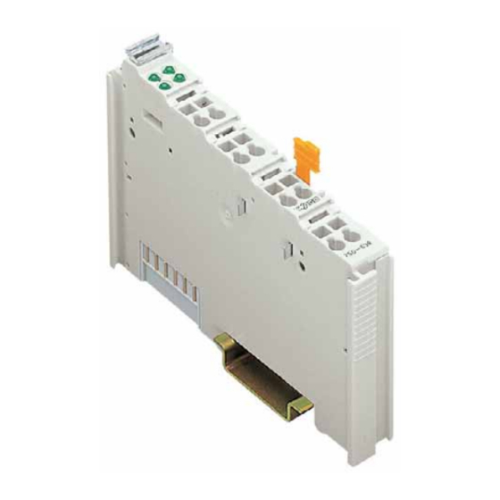
750-650 (/xxx-xxx) [Serial Interface RS 232 C] • 5 Variations 2 I/O Modules 2.1 Special Modules 2.1.1 750-650 (/xxx-xxx) [Serial Interface RS 232 C] 2.1.1.1 Variations Item-No. Designation Description 750-650 RS 232 C/ 9600/ N/ 8/ 1 Baud rate: 9600 baud;... - Page 6 6 • 750-650 (/xxx-xxx) [Serial Interface RS 232 C] View 2.1.1.2 View 13 14 Function Data contacts Common Common (ground) (ground) Shield Shield (screen) (screen) 750-650 Fig. 2.1.1-1: View g065000e 2.1.1.3 Description This interface allows the connection of any device which is equipped with a RS 232 C serial interface.
- Page 7 This module has no power contacts. For field supply to downstream I/O modules, a supply module will be needed. The serial interface module 750-650 and its variations can be used with all couplers/controllers of the WAGO-I/O-SYSTEM 750 (except for the economy types 750-320, -323, -324 and -327).
-
Page 8: Display Elements
8 • 750-650 (/xxx-xxx) [Serial Interface RS 232 C] Display Elements 2.1.1.4 Display Elements Channel State Function Function No operational readiness or the internal data bus communication is interrupted green Operational readiness and trouble-free internal data bus communication signal transfer TxD green no signal transfer TxD Fig. -
Page 9: Technical Data
Busklemmen • 9 750-650 (/xxx-xxx) [Serial Interface RS 232 C] 2.1.1.6 Technical Data Module Specific Data Transmission channel 1 TxD / 1 RxD, full duplex Baud rate 1200 ... 19200 baud Bit skew < 3 % Current consumption max. 55 mA RS 232 C-line length max. - Page 10 WAGO-I/O-SYSTEM 750 System Description 2.1.1.7 Functional description The interface module is designed to operate with all WAGO I/O fieldbus couplers. The serial interface module allows the connection of RS 232- Interface devices to the WAGO I/O SYSTEM. The RS 232 Interface module can provide gateways within the fieldbus protocol.
-
Page 11: Process Image
750-650 (/xxx-xxx) [Serial Interface RS 232 C] 2.1.1.8 Process Image Using the I/O module 750-650, a 6 byte input and output process image can be transferred to the fieldbus coupler / controller via one logical channel. The transfer of the data to be transmitted and the received data is made via 5 output and 5 input bytes (D0 ... -
Page 12: Status Byte
12 • 750-650 (/xxx-xxx) [Serial Interface RS 232 C] Process Image Status byte Bit 7 Bit 6 Bit 5 Bit 4 Bit 3 Bit 2 Bit 1 Bit 0 IL 2 IL 1 IL 0 BUF_F Transmit acknowledge Receive request... - Page 13 Busklemmen • 13 750-650 (/xxx-xxx) [Serial Interface RS 232 C] 2.1.1.9 Datatransfer With the control and status byte the controlling of the sending and receive mode takes place. Requests are indicated by a bit change of state. An assigned bit indicates execution by adopting the value of the request bit.
- Page 14 14 • 750-650 (/xxx-xxx) [Serial Interface RS 232 C] Datatransfer 2.1.1.9.1 Example The module is initialized. The initialization bit in the control byte is set. Output byte 0 Control byte Output byte 2 Output byte 1 0x00 '0000.0100' 0x00 0x00 After the initialization has been executed, the status byte will give back 000.0100.
- Page 15 Busklemmen • 15 750-650 (/xxx-xxx) [Serial Interface RS 232 C] The last 2 characters and the buffer length of 2 are transmitted. Output byte 0 Control byte Output byte 2 Output byte 1 "1" '0010.0001' "o" (0x6F) The transmission request bit (TR) is inverted.
- Page 16 16 • 750-650 (/xxx-xxx) [Serial Interface RS 232 C] Datatransfer If RARR, the receiving of additional characters will continue. Input byte 0 Status byte Input byte 2 Input byte 1 '0XXX. 0X1X' No received data available. '0001.0X0X' The information is in the input bytes.
- Page 17 The presetting is Baud rate: 9600 baud, data bits: 8, Parity: none, stop bits: 1. In this mode of operation the module has the same behavior and also the same process values as the base module 750-650. If another mode of operation is selected by changing the parameters, then the module behaves according to the variation with the selected mode of operation.
- Page 18 Bit 2 of the status byte is reset when bit 3 of the control byte is set. * default setting More Information Detailed Information about the parameterizing this module can be found in the manual for the software tool WAGO-I/O-CHECK or in the Internet under: http://www.wago.com WAGO-I/O-SYSTEM 750 Busklemmen...
- Page 19 Busklemmen • 19 750-650 (/xxx-xxx) [Serial Interface RS 232 C] WAGO-I/O-SYSTEM 750 Busklemmen...
- Page 20 WAGO Kontakttechnik GmbH & Co. KG Postfach 2880 • D-32385 Minden Hansastraße 27 • D-32423 Minden Phone: 05 71/8 87 – 0 Fax: 05 71/8 87 – 1 69 E-Mail: info@wago.com Internet: http://www.wago.com...
Need help?
Do you have a question about the 750-650 and is the answer not in the manual?
Questions and answers