Table of Contents
Advertisement
Quick Links
Download this manual
See also:
User Manual
Advertisement
Table of Contents

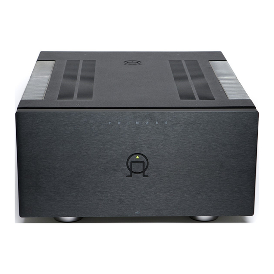
Summary of Contents for Primare A32
- Page 1 PRIMARE A32 Power Amplifier Service Manual...
- Page 2 Technical Description. Error codes. Bias Adjustment. Schematics. Technical Specifications.
-
Page 3: Temperature Protection
When power is first applied and the standby button on the front panel are pressed down the A32 are going to initiate the startup sequence. Relay K1 will be turned on where after a small delay will follow before relay K2 goes active to disable the inrush limiters. At the same time bias are turned on by shutting down the voltage supplied to the optocouplers on the amplifier channels. -
Page 4: General Protection
General Protection During operation mode DC-offset, fuse, temperature and AC-loss are constantly monitored, any abnormal function from these will immediately disengage the speaker relay and the standby LED will start to flash rapidly indicating that an error has been spotted. The error code can be checked by pressing the error check button (SW1), if more than one error at the same time a repeated press of the button will display the next error. -
Page 5: Bias Adjustment
Bias Adjustment Critical for the adjustment are that the mainsvoltage is 230V or 120V exactly. The temperature in the facility must be constant during the adjustment procedure. Use the Bias test points and potentiometers (R1, R2) to adjust bias on each channel. The lower potentiometer is accessible thru a hole in the bottom of the amplifier. - Page 6 1. Switch the amplifier on or if it has been on burn-in (test), disconnect input signal and loads. The A32 amplifier must be in operate mode, bias will be switched off in standby. 2. Let the amplifier run for 1h, without input signal.
- Page 7 LD1085V33 +3.3VD Vout T500mA PCB 2 PLUG +3.3V 100U/6.3V PHONEJACK STEREO SW BRIDGE1 100n 100n 240V BC846 LL4148 LL4148 PLUG SW120-240 TRANSF53X44 +3.3VD +3.3V 470K LL4148 Standby mode 47nF/275V X2 330N 100N 510R LL4148 LL4148 100N PHONEJACK STEREO SW 100N BCV46 SW-SPDT RELAY DPDT3...
- Page 9 +15V R212 Q65 2SC4793 R297 +50V-POWER +50V 7815 R306 +15V R292 TL071 6.3A 0.1U -15V +50V +50V-POWER C101 0.1U C131 110R 100U/63V 1U/250V 10U/50V C106 BS107 C128 100N 100n C102 C129 100n 220U/35V 0.1U 2SA970 R216 470U/35V 100U/63V 2SC5171 2SA970 330R DC-CHECK + R230...
- Page 11 PLUG PLUG 15000/63V 15000/63V 15000/63V PLUG BRIDGE1 PLUG 15000/63V 15000/63V 15000/63V PLUG BRIDGE1 PLUG PLUG PLUG PLUG 15000/63V 15000/63V 15000/63V MRS25 PLUG BRIDGE1 PLUG MRS25 15000/63V 15000/63V 15000/63V PLUG BRIDGE1 PLUG PLUG Title Size Number Revision Date: 7-Dec-2005 Sheet of File: C:\WORK\..\P2005-4B.SCH Drawn By:...
-
Page 13: Performance Data
Performance Data 2000VA Torodial Transformer. A total of 180 000 uF electrolytes in the powersupply. Dual set of Speakerterminals for each channel. Balanced (RCA) and Unbalanced (XLR) inputs. Input impedance 15K, RCA and XLR Output Power (both channel driven): 2x250W 8Ohms load 20Hz-20Khz 2x400W 4Ohms load 20Hz-20Khz THD+N below 0.05% in both cases.


Need help?
Do you have a question about the A32 and is the answer not in the manual?
Questions and answers
Mijn versterker springt regelmatig op de beveiliging ook als hij kort aan staat hij gaat dan snel knipperen mvg teun
The Primare A32 amplifier frequently goes into protection mode and blinks quickly because it constantly monitors DC-offset, fuse, temperature, and AC-loss. If any abnormal function is detected in these parameters, the speaker relay is immediately disengaged, and the standby LED starts flashing rapidly to indicate a fault.
This answer is automatically generated