Table of Contents
Advertisement
Quick Links
Advertisement
Table of Contents

Related Manuals for Mityvac MV5545


Summary of Contents for Mityvac MV5545
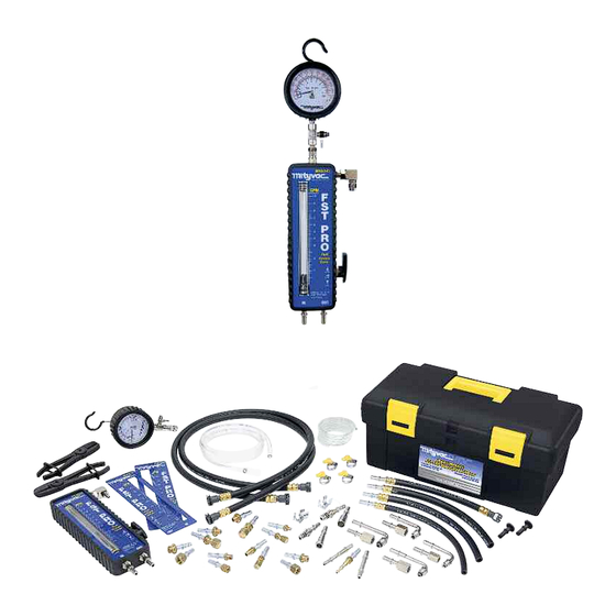
- Page 1 FST PRO FUEL SYSTEM TESTER MODEL MV5545 USER’S MANUAL...
-
Page 2: Table Of Contents
Contents Introduction ..........3 Safety Precautions . -
Page 3: Introduction
Wear gloves and protective clothing to avoid the contact of Introduction gasoline on skin. If contact occurs, immediately wash the The Mityvac FST Pro Fuel System Tester is an advanced area and perform necessary first aid diagnostic tool designed for troubleshooting and pinpointing •... - Page 4 Standard Kit Components Part Number Description 824141 High Pressure Gauge 824149 Pressure Relief Hose (1/8"/3mm ID x 6'/1.8 m long) 824141 824148 Bypass Hose (1/4"/6.5 mm ID x 6'/1.8 m long) 824144 Scissor Hose Clamps (Qty 2) 824147 Flowmeter Hose (3/8"/9.5 mm ID x 4'/1.2 m long) 824149 824148 824173...
-
Page 5: Service Parts
Service Parts Part Number Description 824182 Flow Tube Shield 824177 Male Quick-Connect Fitting 824176 Bypass Port 824175 Flow Control Valve Knob 824174 Flowmeter Inlet/Outlet Connector (Qty 2) 824146 Flow Control Valve 824145 Flowmeter Seal Kit 824183 Wing-Style Hose Clamp (Qty 4) 824181 Flowmeter Boot 824180... -
Page 6: Fuel System Test Adapters
European vehicles MVA517 Ball Nose Adapter with CIS fuel system M14 x 1.5 European vehicles MVA518 Ball Nose Adapter with CIS fuel system Page Number - 6 ** Not included in MV5545. Available individually or in MVA5552 Pressure Test Accessory Kit... -
Page 7: Fuel System Test Adapters
Fuel System Test Adapters Reference Description Applications Order No. M16 x 1.5 European vehicles MVA519 Ball Nose Adapter with CIS fuel system M16 x 1.5 Adapter GM Vortec MVA520 M14 x 1.25 Adapter GM Vortec MVA521 Carbureted & early ⁄ "... -
Page 8: Assembly
Assembly For flexibility and ease of storage, the FST Pro features a modular design that is quick to assemble and breakdown. Proper assembly for testing is covered in the Setup and Installation instructions Bypass Hose Prior to the first use of the FST, the 1/4" (6.5 mm) ID clear bypass hose should be assembled to the bypass port extending from the side of the flowmeter, above the flow control valve. -
Page 9: Adapters
To release the connection, press and hold the release button on the side of the female quick-connect, while pulling the connection apart (Fig. 8). Do not attempt to release the quick-connect connection using a disconnect tool, as this may damage the fitting. Replacement clips are included if needed Adapters The FST Pro includes a selection of adapters for connecting inline with... -
Page 10: Flex Hose Connections
Flex Hose Connections In many cases it is convenient to connect the FST Pro into the fuel delivery system at a location where a flexible rubber hose is secured to a steel fuel line using a screw clamp. A special adapter set is included with the FST Pro for installing it into this type of connection. -
Page 11: Principle Of Operation
Principle of Operation the technician to simulate varying load conditions on the engine while the vehicle is idling in the shop. These functions are Fuel Delivery Basics performed by means of a pressure gauge, flow gauge (flowmeter), and a patented flow control valve. Modern fuel injected engines rely on precision fuel delivery to perform at peak output and efficiency. -
Page 12: Simulating Engine Demand
In regards to return fuel systems, knowing the pressure and flow at idle is a very good indication as to whether the fuel system is functioning properly. However, while pressure can be compared to a manufacturer’s spec, idle flow is not typically documented. Most return fuel systems will flow around .5 gallons (2 liters) per minute at idle. -
Page 13: Pinpointing Fuel System Malfunctions
When the valve is rotated to the BYPASS position pointing up, fuel is routed through the bypass port located on the side of the flowmeter just above the flow control valve (Fig. 20). Bypassing eliminates all restriction to the flow, and the maximum volume output of the pump is indicated on the flowmeter. -
Page 14: Types Of Fuel Delivery Systems
Types of Fuel Delivery Systems For the purpose of accurately applying and testing with the FST Pro, today’s fuel delivery systems can be divided into three typical configurations: • Return (Bypass) Fuel Systems • Returnless Fuel Systems – Mechanically Regulated •... -
Page 15: Mechanically Regulated
Returnless fuel systems (mechanically regulated) were pioneered by Chrysler in the mid-90s. Since that date, other car manufacturers have been implementing returnless systems onto their cars. Now returnless systems are common on most all new cars and light trucks. Mechanically Regulated In the case of mechanically regulated returnless systems, the term “returnless”... -
Page 16: Electronically Regulated
Electronically Regulated Fuel Filter Fuel Supply Line Ford began developing an electronically regulated returnless fuel Pressure Test Port delivery system in the late nineties, and began implementing it on Pump Module their cars in the early to mid-2000s. This system shares some of the Fuel Rail features and benefits of both return and returnless systems, but with the addition of advanced control technology. -
Page 17: Fuel System Components
Fuel System Components peak capability of the pump. The manufacturer’s service manual should document this in their fuel system diagnostic procedure. The modern fuel delivery system is comprised of several critical Fuel pumps fail or fail to perform due to high mileage, components. -
Page 18: Fuel Filter
A clogged inlet strainer can starve the fuel pump of fuel, causing high. This causes the regulator to pass more fuel back to the it to cavitate. Cavitation will create rapid changes in fuel density, tank, lowering fuel pressure in the rail. When the throttle is causing the float in the FST flowmeter to bounce up and down. -
Page 19: Setup And Installation
If the connection has to be forced, or if there is looseness in the connection, do not attempt to pressurize the system. Contact the Mityvac technical service department at the number on the front of this manual if there are any questions or concerns about the connec- tion. -
Page 20: Setting Up The Fst Pro
reduce fuel spillage, whenever possible, try to select the required adapters before disconnecting the fuel line, and have them ready to install. Setting-up the FST Pro Once the installation point has been determined, follow the instruc- tions below to setup the tester prior to disconnecting the fuel line. 1. - Page 21 7. Connect the hose extending from the flowmeter connection labeled “IN”, to the other end of the adapter (Fig. 36). 8. Install the second FST connection adapter to the fuel line running to the fuel rail. If the fuel line connection used by the vehicle man- ufacturer is a 3/8”...
-
Page 22: Testing And Diagnostics
Testing and Diagnostics Testing and diagnostic procedures vary depending on the type of fuel delivery system. Prior to testing, the fuel delivery system must be identified as Return, Returnless (mechanically regulated) or Returnless (electronically regulated). For detailed information on fuel delivery sys- tems and how to identify them, refer to the section entitled Types of Fuel Delivery Systems, earlier in this manual. - Page 23 At idle, the volume of fuel flowing through the tester should remain steady between 0.3 and 0.6 gallons per minute (GPM) or 1.1 and 2.2 liters per minute (LPM). 6. Noting the values for pressure and volume, if either is out of range, these are indications of a problem with one or more com- ponents of the fuel system.
- Page 24 continues to experience symptoms of a fuel delivery malfunction, it could be caused by contaminated fuel, faulty fuel injector(s), or an intermittent component malfunction such as a sticking pressure regu- lator or loose electrical connection. Follow the vehicle manufacturer’s recommended procedures for the inspection and repair of these com- ponents.
- Page 25 Under-restricting Fuel Pressure Regulator An under-restricting pressure regulator will cause the idle pressure in Zones 1 and 2 to drop below spec, and the idle flow to be higher than normal. If this is what the FST is indicating, and the peak pressure and flow are normal, then the cause is most certainly the pressure regulator.
-
Page 26: Returnless Fuel Systems (Mechanical)
Returnless Fuel Delivery Systems (Mechanically Regulated) At this point, it is assumed that the FST has been properly installed inline with the fuel delivery system as recommended, and that it has been primed to ensure no leaks are present (See FST Pro Setup and Installation). - Page 27 OPEN position. Peak Demand Test 7. Note the vehicle’s engine size and maximum engine speed (RPM). Refer to the Maximum Engine Fuel Volume Requirements table (Appendix A), and use the size and speed values to determine the maximum fuel volume requirement of the engine. 8.
-
Page 28: Returnless Fuel Systems (Electronic)
A clogged inlet strainer can cause the fuel pump to cavitate because it is starved for fuel. Cavitation will create rapid changes in fuel densi- ty, causing the float in the FST flowmeter to bounce up and down during the peak flow and/or capability test. It can also cause the nee- dle on the pressure gauge to bounce. - Page 29 After connecting the FST, it is normal to have air trapped in the fuel lines and flowmeter. Cycling the ignition switch (or cranking the engine briefly) with the flow control valve in the BYPASS posi- tion can help purge air from the system. Once fuel fills the flowmeter and flows through the bypass hose, return the valve to the OPEN position.
- Page 30 9. With the car idling, rotate the flow control valve past the 90° CLOSED position towards BYPASS (Fig. 54). Adjust the valve until the flowmeter indicates an amount of fuel flow equivalent to the value for the maximum engine fuel volume taken from the table (Fig.
-
Page 31: Fuel Visualization
ty, causing the float in the FST flowmeter to bounce up and down during the peak flow and/or capability test. It can also cause the nee- dle on the pressure gauge to bounce. In addition, as the pump tries to pull gas through the clogged strainer, it creates a pressure drop that may cause air bubbles to form and become visible. -
Page 32: Disconnecting The Fst
5. Turn off the engine and immediately clamp off the FST inlet hose running to the tester from the fuel supply line. This will trap the pressure gauge between the clamp, the fuel rail, the pressure reg- ulator, and the fuel return line. 6. - Page 33 the hose is clamped, quickly disconnect the hose from the fuel system before the pressure has time to build. Try to keep a shop towel wrapped around the connection to catch any fuel spray. 4. Rotate the flow control valve to the CLOSED position to help pre- vent fuel leakage.
-
Page 34: Appendix A
Appendix A Maximum Engine Fuel Volume Requirements (Gallons/Minute) Engine Size Engine Speed (RPM) liters 3000 4000 5000 6000 7000 8000 0.05 0.06 0.07 0.09 0.10 0.12 0.06 0.07 0.09 0.11 0.12 0.14 0.06 0.08 0.10 0.12 0.15 0.17 0.07 0.10 0.12 0.14 0.17... - Page 35 Appendix A Maximum Engine Fuel Volume Requirements (Liters/Minute) Engine Size Engine Speed (RPM) liters 3000 4000 5000 6000 7000 8000 0.19 0.23 0.26 0.34 0.38 0.45 0.23 0.26 0.34 0.42 0.45 0.53 0.23 0.30 0.38 0.45 0.57 0.64 0.26 0.38 0.45 0.53 0.64...
-
Page 36: Appendix B
Appendix B – Return Fuel System Diagnostic Guide Results Idle Idle Flow Peak Pressure Peak Flow Potential Causes Scenario Pressure Greater than 50% to maximum fuel .7 to 1.0 GPM Fuel system is operat- Normal Normal Normal 100% higher Normal volume require- (2.5 to 4.0 LPM) ing normally... - Page 37 Appendix B Return Fuel System Diagnostic Guide Scenario 2 Diagnosis: A restriction to the supply of fuel to the engine such as a clogged inlet strainer, inline filter, or pinched fuel supply line will reduce the flow of fuel. However, pressure will remain normal or drop only 1 or 2 psi below spec.
-
Page 38: Appendix C
Appendix C – Returnless (mechanically regulated) Fuel System Diagnostic Guide Results Idle Peak Flow Peak Demand Pressure Potential Causes Scenario Pressure Less than .7 to 1.0 GPM Fuel system is operating Normal Normal Normal 10% below (2.5 to 4.0 LPM) normally idle pressure Greater than... - Page 39 Appendix C Returnless (Mechanically Regulated) Fuel System Diagnostic Guide Scenario 2 Diagnosis: A restriction to the supply of fuel to the engine such as a clogged inlet screen, inline filter, or pinched fuel supply line will reduce the flow of fuel. This will be evident by the reduction in peak flow.
-
Page 40: Appendix D
Appendix D – Returnless (Electronically Regulated) Fuel System Diagnostic Guide Results Idle Peak Demand Pressure Peak Pressure Peak Flow Potential Causes Scenario Pressure Less than 50% to .7 to 1.0 GPM Fuel system is Normal Normal 10% below Normal 100% higher Normal (2.5 to 4.0 LPM) operating normally... - Page 41 Appendix D Returnless (Electronically Regulated) Fuel System Diagnostic Guide Scenario 2 Diagnosis: A restriction to the supply of fuel to the engine such as a clogged inlet strainer, inline filter, or pinched fuel supply line will reduce the flow of fuel. However, idle and peak pressure will remain normal or drop only 1 or 2 psi below manufacturer’s specification.
Need help?
Do you have a question about the MV5545 and is the answer not in the manual?
Questions and answers