Table of Contents
Advertisement
Advertisement
Table of Contents

Summary of Contents for Neoden Tech Neoden 4
- Page 1 User Manual Neoden 4 www.montaz-elektroniki.pl...
-
Page 2: Table Of Contents
Content Structure of Neoden 4 ........................I Procedure for making a programming file..................II Edit on the Operation Interface......................II I. Edit on the Interface.........................1 1.PCB Feed Setting........................1 2.Setting Panelized PCB & first chip( manual is the same as automatic download)....2 3. -
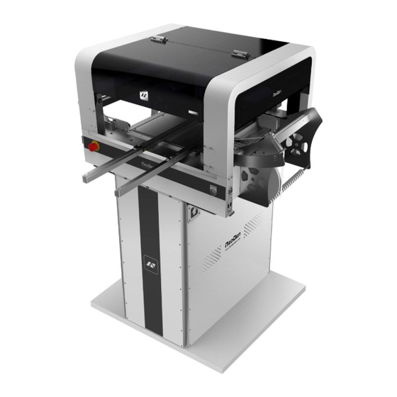
Page 3: Structure Of Neoden 4
Structure of NeoDen 4 ①:Placement head ②: Nozzle ③:Rails ④:Vibration feeder ⑤:On/Off button ⑥:Conveyor port ⑦:Multi-hole positioning board ⑧:Feed box ⑨:Peel box ⑩:Emergency button ⑪:Power switch ⑫:Rack shelf ⑬:Acrylic cover ⑭:Foot Mounts ⑮:Fixed support Each part mentioned above can be disassembled and tested. -
Page 4: Procedure For Making A Programming File
Procedure for making a programming file See P1 1. PCB feed setting See P5 Save 2.Chip list Edit Select file See P7 and start Start return file 3.Feeder setting working file See P2 4.Panelized PCB first chip setting See P4 5.Mark point setting Note: The basic procedure of making a programming file for manual programming or direct PCB file is similar, but there are two different parts: chip list and mark point setting. -
Page 5: Edit On The Operation Interface
Edit on the Operation Interface I. Edit on the Interface See below Fig.: Edit Interface 1.PCB Feed Setting Function:Used to confirm the feeding place,first edit item in manual program Introduction of function keys: (1) Tray Fixation:Once selected tray fixation,the setting items of board feeding will be closed.We only need use the positioning column to fix the board. -
Page 6: Setting Panelized Pcb & First Chip( Manual Is The Same As Automatic Download)
camera until to the limited place by clicking the image(See fig.3).Click “Save” item to save the setting,return to the main page to finish the setting. Fig.2 Fig.3 (3) Multiple rail feed: (4) Eject PCB front-side:Once selected this item,the PCB will eject at front side when finish mounting.If don’t select,the PCB will eject at back side. - Page 7 Operation introduction (1) Single PCB: Only need to enter “1” in the row and column, some other useless function will turn grey. The “left bottom” is functional, which means the first PCB.Then you can press “align” to go to the screen of vision and get the coordinate of first component, see image 2-2. Fig.2-2 After saving the coordinate, the screen will automatically turn back to “PCB information”...
-
Page 8: Pcb Mark Point Setting
After setup, click “create panelized list”, the data will be generated accordingly in the blank. PCB angle correction Bad board detection 3. PCB mark point setting Fig.3-1 Function: After completing setup of the mark points, with which the machine can locate the position of PCB and identify the set up mark points, so that the next step can be followed Operation method: (1) Mark point on single PCB: this mainly applies on single PCB or a whole board that consists of... -
Page 9: Component List Settings
Import coordinate: according to the PCB schematic, we get the coordinate of mark and write down manually. Manual programming: when it’s in Manual Programming status, the function “Alignment” of Mark will be effective. Click on it, the camera will go and collect the coordinate of mark (see image 3-2), save it and go back. - Page 10 Fig. 4-1, one component has been found Find and confirm one component’s coordinate by using the function of “Movement Mode”-Click to move (Visual field/Overall Workbench).Once clicked the “Save” item,the interface will automatic back to main page,then input the corresponding values(Designator refer to the location,Specification refer to the value of resistance,Footprint refer to the normal package info,I.e.0603,0805,1206,Etc.Angle value should be set according to the required direction on the PCB and polarity ,horizontal direction(0 or 180 degree),vertical direction(90 or -90 degree).the...
-
Page 11: Feeder Configuration
Fig.4-2 5. Feeder configuration Functions:All components’ configurations will be set here for every working file,I.e.(Nozzle selection,Feeder selection,Pick up position,Correction setting and other parameters) www.montaz-elektroniki.pl... - Page 12 (1) Feeders Arrangement:Left Feeders(Feeder20-48),Right Feeders(Feeder1-19),Special Feeders(Feeder49-58).Above feeders’ setting is under the ideal situation.According to the Required Tape’s width from customers,the quantities maybe be cut down.For example,if there are a lot of components’ information under the “Chip List”item,choose the feeder number and you will find the drop-down symbol,will display all components’...
- Page 13 Function:Use to set the components’ information from tray and tube packages,complete picking up operation for special feeders by changing the values Feeder basic information Fig.5-1 Fig.5-2 Pick position X/Y:First have to lock the position of component on the feeder(See fig.5-2),once saved the modification, the XY date will automatically change to the ones after alignment.
-
Page 14: File Mounting
Function:Select corresponding nozzles(one or more than one all acceptable)according to the components and the nozzle have set on the machine,then the machine will automatic assign to each feeder in order to meet the requirements pf single head work or multi heads working together.Also have detect functions on this item. - Page 15 1.Method to mount one file: First select one file, click”mount”, then you will enter into one mounting page, above picture is an example of one file in mounting. (1) On the top-left corner shows mounting process, chip list---by the variation of blue line, you can track process of mounting constantly.
-
Page 16: Manual Test
III. Manual Test Function: Used for testing the basic functions, connection between software and hardware is the mainly function, details about testing as below: 1.Placement head Choose nozzle 1, nozzle 2, nozzle 3, nozzle 4 to test separately Blow, after click this option, air will blow-off from selected nozzle ... -
Page 17: Rail Control
2. Rail control Function, test rail PCB feeding,forward PCB feeding, backward PCB feeding and feeding speed 3. Hose control Function, test each function key Start button status, on the left side of machine, it has one start button, press this button the ... -
Page 18: Feeder Test
4. Feeder test Function, test each feeder’s matching and feed box & peel box’s function. First, select” Feed-box and peel-box linkage”, then test function of feed box and peel box. (1) click any feeder randomly, feed box and peel box will appear corresponding actions IV. - Page 19 As pic show, function description of button on right side Save configuration: click it for saving after modify the parameters Modify password: click it, put into the password, then finish change the fourth page which is also the System interface. Set up feeder ID: click and show as pic above.
-
Page 20: Feeder Configuration
Version upgrade: After receiving our new version file, you can upload it with clicking “version upgrade” to finish. ENGLISH:Change to the English version. 1、Feeder configuration As figure show: parameters setting for all feeders. First list on left side is feeder No. X,Y parameters is setting the feeder’s pick position. - Page 21 Save after setting well the pick position of the feeder. Same way as in the file. “Feed-box” setting It is used to set the feed-box ID. E.g., if you insert the feed-box 2 in the port 1, then it need to set the feed-box ID to be 2 “Peel Box”setting “Peel box”...
- Page 22 For example,the default port ID for Stack 33 is 33,if the port 33 is broken and want to change to port 34,can set in this item “Feed test” Once clicked this item,then the machine will start Feed test,feed one component and help check whether the feed is normal www.montaz-elektroniki.pl...
-
Page 23: Feed Setting
2. Feed setting Function:Used to setting values for all stacks Feed rate:The distance between two components,default value 4mm,for 0402,should set 2mm. Strength Setting:Motor torque of feed for the stack(Normally no need to change). Test:The machine will do feed test separate after clicking this item,peel box won’t work during above test Alignment:Click peel box,the motor idling several rings to do the initial position of the calibration. -
Page 24: System Setting
Function:Peel configuration as above figure show,used to set the values for all peel boxes Feed rate:Similar meaning in Feed box part,mean length of rotation each time Strength:Torque setting of Peel motor(Plastic tape will be difficult strip away in the case of being affected with damp, can adjust bigger values of motor torque here) Test:The machine will do peel test separate after clicking this item,feed box won’t work during above test 4. - Page 25 Function: it is mainly for correction the position of suction nozzle.(Notice: In case change by mistake,we ‘ ve locked it by password. It can be changed by clicking the button of Password change and then insert password. Strongly recommend operating it under our engineer ’ s guidance).
- Page 26 Operation steps: 1.click the button of LENS ROTATION to let machine take photos of nozzle’s 360 degree rotation . 2.click the central point of nozzle 3. Click the save button. Relative position of nozzle 1 and camera: it is for the synchronism of nozzle and camera, ...
Need help?
Do you have a question about the Neoden 4 and is the answer not in the manual?
Questions and answers