
Related Manuals for Renogy MT-50


Summary of Contents for Renogy MT-50
- Page 1 MT-50 Remote Tracer Meter RENOGY Remote Tracer Meter for Commander Series and ViewStar Series Charge Controllers 2775 E. Philadelphia St., Ontario CA 91761 1-800-330-8678 Version 2.0...
-
Page 2: Table Of Contents
Table of Contents General Information ...................... 3 Identification of Parts ....................4 Installation ........................5 Frame Wall Mount Installation .................. 5 Flush Wall Mount Installation ................... 6 Operation ........................6 Menu Display ......................6 Monitoring ......................7 Device Info ......................9 Test Operation .................... -
Page 3: General Information
The information is displayed on a backlit LCD display and is easily navigated using the buttons on the meter. The MT-50 could also be flush mounted on a wall or flat surface using the mounting frame provided. -
Page 4: Identification Of Parts
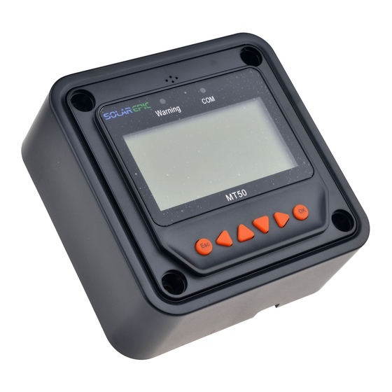
Identification of Parts Key Parts 1. Communication Indicator (Green) 2. Alarm Sound port (Alarm will be discontinued in new models) 3. Warning Indicator (Red) 4. 4 X Mounting Holes 5. Display Screen 6. Navigation Buttons 7. RS485 Port... -
Page 5: Installation
Resolve any issues before installing the meter and the meter cable. The MT-50 can be mounted in two ways: Frame Wall Mount or in a Flush Wall Mount. A plastic mounting frame has been included for the purpose of Frame Wall Mounting. If Flush Wall Mounting then the MT-50 faceplate sits flush with the mounting surface and the body of the meter would be able to rest comfortably in a hole cut-out on the mounting surface. -
Page 6: Flush Wall Mount Installation
Flush Wall Mount Installation This is a low-profile installation. The faceplate of the MT-50 sits flush with the mounting surface or wall and the body of the meter rests in a hole cut-out on the mounting surface. The meter wiring is concealed behind the mounting surface, or the interior of the wall. -
Page 7: Monitoring
NOTE: To customize charge parameters, Battery Type must be set to USER, under 4. CONTROL PARAMETERS NOTE: The values found in your controller are default values and will not necessarily match the ones listed. The values on this table are to show the user what the different screens are used for. 1. - Page 8 Demonstrates Battery Temperature, the Max. Battery Voltage detected and the Minimum Voltage 0.00 °C Temperature: Detected by the Battery. Max Voltage: 0.00 V Min Voltage: 2.4 V Battery This screen gives the user a visual of battery Charge: No Charge status beyond voltage,...
-
Page 9: Device Info
2. Device Info NOTE: Use the up and down arrows to maneuver through the monitoring menus. The left and right arrows indicate submenus and display further information regarding the system Displays device info for the charge controller and VS2024BN the next menu displays the charge controller name Rate.Vol: and screen number. - Page 10 Temperature fluctuation can affect performance in the system. Therefore, the purpose of temperature compensation is to adjust the performance of the Temp Comp. Coeff system to keep the system functioning normally. -3mV/°C/2V Choose from 0mV to -9mV Rated Voltage Choose between 12V, 24V or AUTO for rated Auto battery voltage.
-
Page 11: Load Set
If using the SOC for battery management, then Battery Charge SOC these parameters let the Charge Controller/Tracer 100% know the SOC of the battery based on these Battery Discharge SOC boundary limits. NOTE: This function will be discontinued in future models. - Page 12 In Light On/Off the user sets to load to be operated 0Manual Control by the time of day. √Light on/Off 0Light on+Timer The load terminal automatically turns ON when the 0Timer Control solar voltage goes BELOW the point of NTTV (Night Time Threshold...
-
Page 13: Device Parameters
6. Device Parameters NOTE: Use the up and down arrows to maneuver through the monitoring menus. The left and right arrows indicate submenus and display further information regarding the system NOTE: Press OK to change from reading mode to parameter setting mode. Once the parameter is highlighted, use the UP and DOWN arrows to adjust the setting and press OK once again to save the setting. -
Page 14: Failure Info
UP and DOWN arrows to adjust the setting and press OK once again to save the setting. First screen displays information regarding the Meter Parameters controller and the tracer type. Type: MT-50 Version: version # SN: SN # The Switch-Pages feature allows the menu screens, under Monitoring, to cycle through the Meter Parameters displays at every second desired by the user. -
Page 15: System Status Icons
System Status Icons BATTERY SYSTEM LOAD Day/ PV Battery System Load Charging Charging Normal Night/ PV Battery System Load Level Full Under Charging Voltage Battery System Over Over Discharge Discharged System Status Glossary PV Status Meaning Connect PV is Connected Disconnect PV is Disconnected Measure Err... -
Page 16: Failure Information
BATT Status Meaning Equalize Battery is equalizing Boost Battery is in boost mode Float Battery is in float mode NoCharge No charge to battery Low voltage disconnect Under voltage warning Normal Battery is normal Over voltage disconnect Disc.O.O.Ctrl. Battery experiencing error charging/discharging Ctrler O.Temp. -
Page 17: Device Considerations
4. Solar PV is short circuited. Check connections, disconnect and reconnect. Telecommunication Port When the meter running on individual power or the communication is cut off, the MT-50 will display graphical symbols abnormally. Press any key to stop the display and resume normal activity. -
Page 18: Troubleshooting
Troubleshooting MT-50 has no display • Verify the charge controller is powered on and that it is securely connected to the MT-50. LCD display is dim • Check the system battery voltage. The MT-50 needs a minimum of 8 V to operate. -
Page 19: Charging Parameters
Charging Parameters Battery type Sealed Flooded Default 16.0V; x2/24V 16.0V; x2/24V 16.0V; x2/24V High Volt Disconnect 17.0V; x2/24V 17.0V; x2/24V 17.0V; x2/24V 15.0V; x2/24V 15.0V; x2/24V 15.0V; x2/24V Default 15.5V; x2/24V 15.5V; x2/24V 15.5V; x2/24V Charging Limit Voltage 16.0V; x2/24V 16.0V;... -
Page 20: Threshold Voltage Parameters
Threshold Voltage Parameters The following chart demonstrates the parameters when using the Timer under load settings. Description Parameter Default 5V; x2/24V Day Time Threshold Voltage (DTTV) 10V; x2/24V 1V; x2/24V Default 6V; x2/24V Night Time Threshold Voltage (NTTV) 10V; x2/24V 1V;... -
Page 21: Cad Dimensions
CAD Dimensions NOTE: Dimensions are in millimeters...
Need help?
Do you have a question about the MT-50 and is the answer not in the manual?
Questions and answers