Table of Contents
Advertisement
Advertisement
Table of Contents
Troubleshooting

Related Manuals for DRE Waveline EZ

Summary of Contents for DRE Waveline EZ
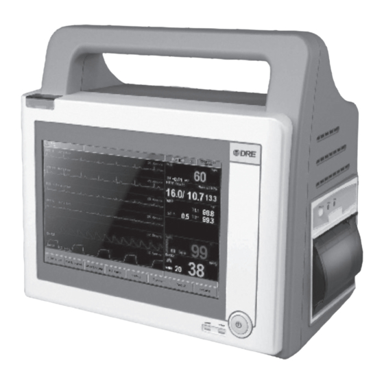
- Page 1 DRE Waveline EZ Service Manual...
- Page 2 SERVICE MANUAL Waveline EZ Patient Monitor Caution: Federal law (U.S.A.) restricts this device to sale by or on the order of a physician. © 2010 DRE, Inc. All rights reserved. Ver 1.0, Issued date: Dec 28, 2010...
- Page 3 DRE Inc. Website: www.dremed.com Address: 1800 Williamson Court Louisville, KY 40223 USA Toll Free (US call only): 502-244-4444 To obtain information about a warranty, if any, for this product, contact DRE Technical Services or your local DRE representative.
-
Page 4: Table Of Contents
SECTION 1: INTRODUCTION ........................4 1.1 MANUAL OVERVIEW ........................... 4 1.2 WARNINGS, CAUTIONS AND NOTES ....................4 1.3 Waveline EZ PATIENT MONITOR DESCRIPTION ................4 1.4 RELATED DOCUMENTS ........................5 SECTION 2: INTRODUCTION AND SYSTEM DESCRIPTION .............. 6 2.1 SYSTEM OVERVIEW ..........................6 2.2 SYSTEM BLOCK DIAGRAM ......................... - Page 5 Service Manual for Waveline EZ 3.3 PERFORMANCE TESTS ........................25 3.3.1 BATTERY CHARGE ........................ 26 3.3.2 BATTERY PERFORMANCE TEST ..................26 3.3.3 POWER-ON SELF-TEST ....................... 26 3.3.4 HARDWARE AND SOFTWARE TESTS ................27 3.3.5 OPERATION WITH A HUMAN SUBJECT ................28 3.4 SAFETY TESTS ............................
- Page 6 Table 3-5: Patient Leakage Current Values— Mains Voltage on Applied Part ………………31 Table 3-6: Test Lead Combinations …………………………………………………………………32 Table 3-7: Allowable Leakage Current ………………………………………………………………32 Table 6-1: Waveline EZ spare parts list …………………………..…………………………… 40 Table 6-2: Waveline EZ Accessories ………………………..……………………………………41 Table 7-1: Problem Categories ………………………………………………………………………43 Table 7-2: Lists recommended actions to address power problems ……………………………44...
-
Page 7: Section 1: Introduction
Built-in battery facilitates transportation of patient. The purpose and function of the Waveline EZ monitor is to monitor ECG, heart rate, NIBP (systolic, diastolic, and mean arterial pressures), SpO2, respiration, temperature, and EtCO2 for adult, neonate and pediatric patients in all hospital areas and hospital-type facilities. -
Page 8: Related Documents
Refer to the Waveline EZ user’s manual. To understand the various sensors, ECG leads, blood pressure cuffs, SPO2 probe and etc. that work with the monitor, refer to the individual directions for use that accompany these accessories. -
Page 9: Section 2: Introduction And System Description
2.1 SYSTEM OVERVIEW 2.1.1 The Complete Waveline EZ Patient Monitor System The Waveline EZ patient monitor is a full-function monitor for use on adult, notate and pediatric patients. The functions performed by the system include monitoring patient ECG, heart rate, respiration rate, non-invasive blood pressures, blood oxygen saturation, ETCO2 and temperature. -
Page 10: Power System
Service Manual for Waveline EZ in the text that follows the illustration. This is followed by more detailed descriptions of the theory of operation of each block. NIBP Patient Connectors Module SpO2 TEMP Module Power Main Board AC Input Supply... -
Page 11: Pin Assignment And Description For Ac-Dc Module
Service Manual for Waveline EZ 2-2: P IGURE OWER YSTEM LOCK IAGRAM 2.2.1.1 PIN ASSIGNMENT AND DESCRIPTION FOR AC-DC MODULE 2-3: P AC-DC IGURE IN ASSIGNMENT FOR MODULE Port CN1: Description AC 100-240V input - 8 -... -
Page 12: Pin Assignment And Description For Dc-Dc Module
Service Manual for Waveline EZ not connected AC 100-240V input Port CN2: Description Ground Ground DCX, output +15vdc for DC/DC module DCX, output +15vdc for DC/DC module 2.2.1.2 PIN ASSIGNMENT AND DESCRIPTION FOR DC-DC MODULE 2-4:P DC-DC IGURE IN ASSIGNMENT FOR MODULE CONTROL1:(Communicate with mainboard)... - Page 13 Service Manual for Waveline EZ DVCC , +5vdc for mainboard power supply DVCC , +5vdc for mainboard power supply NBP:(To NIBP module) Description NBPTXD, RS232 interface of NIBP NBPRXD, RS232 interface of NIBP +12vdc for NIBP power supply Ground Ground +12vdc NET:(To RS232 Interface)
-
Page 14: Dc-Dc Module Test Points
+12vdc output 2.2.2 MAINBOARD (ARM-FPGA SYSTEM,ERT MODULE(ECG, RESP, TEMP,SPO2)) The Waveline EZ main control system adopts control kernels including 32-bit 96 MHz ARM9E based MCU microcontroller and FPGA. The design is modularization. All functional modules communicate each other by the standard UART(Serial). -
Page 15: Pin Assignment And Description For Mainboard
Service Manual for Waveline EZ 2-5: M IGURE AINBOARD LOCK IAGRAM 2.2.2.1 PIN ASSIGNMENT AND DESCRIPTION FOR MAINBOARD Internet Interface SPO2_D CONTROL2 CONTROL1 SJTAG CPU_ LOAD shield cover SJTAG TEMP TOUCH1 SPEAKER 2-6: P IGURE IN ASSIGNMENT FOR MAINBOARD 2.2.2.2 MAINBOARD TEST POINTS... -
Page 16: Fpga
Service Manual for Waveline EZ CF77 Negative lead Primary Ground CF77 Positive lead +3.3vdc output CF65 Positive lead +1.2vdc output CF50 Positive lead +1.8vdc output CF75 Positive lead +3.3vdc output E9 Positive lead +2.5vdc output EP8 Positive lead +3.3vdc output... -
Page 17: Ert Module(Ecg, Resp, Temp, Spo2
2.2.2.5 ERT MODULE(ECG, RESP, TEMP, SPO2) 2.2.2.5.1 OVERVIEW The Waveline EZ ERT module consists of eight major blocks: interface circuit, ECG, respiration, temperature, controls, isolation, and A/D converter on the non-isolated side. The instrument incorporates the standard ECG 3-lead or 5-lead system (I, II, III). It provides two levels of low frequency noise filtering, T-wave filtering, R-wave detection, pacer detection capability and baseline reset. -
Page 18: Nibp Module
Measurement of patient temperature is accomplished by processing the signal from a probe containing a resistor whose impedance is temperature dependent. The class of such components is called thermistor. The Waveline EZ patient monitor is designed to accept the signals from electrically isolated Series... -
Page 19: Figure 2-10: Nibp System Block Diagram
Service Manual for Waveline EZ Prior to making blood pressure measurements, the cuff is placed around a limb, typically an upper arm (left or right). The NIBP measurement system is initiated by commands responding to pressing the NIBP Start/Stop switch on the front panel. The cuff is inflated at a rate controlled by the pump excitation current to a pressure above systolic, at which level the artery is effectively occluded. -
Page 20: Figure 2-11: Oscillatory Characteristics Diagram
Service Manual for Waveline EZ 2-11: O IGURE SCILLATORY HARACTERISTICS IAGRAM WARNING : The width of the cuff should be either 40% of the limb circumference (50% for neonates) or 2/3 of the upper arm length. The inflatable part of the cuff should be long enough to encircle 50-80% of the limb. -
Page 21: Pin Assignment And Description For Nibp Module
Ground +12vdc from DC/DC module 2.2.4 SPO2 MODULE See Figure 2-13. The Waveline EZ contains a saturated blood oxygen measurement module using pulse oximetry techniques for noninvasive monitoring. The SpO section is a separate minisystem with its own analog section, A/D converter and microprocessor. -
Page 22: Display
Service Manual for Waveline EZ venous blood) from the time variant parameters (arterial volume and %SpO2) to identify the pulse rate and calculate oxygen saturation. Oxygen saturation calculations can be performed because oxygen saturated blood predictably absorbs less red light than oxygen depleted blood. - Page 23 Service Manual for Waveline EZ Ground for LED circuit Power for digital circuit Power for digital circuit DE or HV mode control Note 3 Data enable Vsync signal input Hsync signal input Power ground Blue data input (MSB) Blue data input...
-
Page 24: Keyboard (Switches)
Service Manual for Waveline EZ 2.2.6 KEYBOARD (SWITCHES) The keyboard circuit contains touch panel control and two red LEDs(AC Indicator and DC indicator). The LEDs are driven by the power supply system. The keyboard system is illustrated in the diagram below. -
Page 25: Speaker
Service Manual for Waveline EZ capacitance when the overlay experiences a touch. Screen technology measures the frequency changes to determine the X/Y coordinates of the command, giving fast and accurate results. This type of touch screen technology can use a thin, sleek design and robust characteristics for touch;... -
Page 26: Pin Assignment For Recorder Module
Paper Detector UART User Interface Thermal Printer Motor Drive Motor 2-14: R IGURE ECORDER ODULE LOCK IAGRAM 2.2.9.1 PIN ASSIGNMENT FOR RECORDER MODULE 2-15:P IGURE IN ASSIGNMENT FOR ECORDER ODULE POW: Description Ground Ground +8.3vdc from DC/DC module +8.3vdc from DC/DC module SIO:... -
Page 27: Rs-232
Service Manual for Waveline EZ 2.2.10 RS-232 2.2.10.1 OVERVIEW This is a rear panel 9-pin connector providing interfaces with other computer systems or equipment. The driver for this port is a Universal Asynchronous Receive-Transmit (UART) integrated circuit that interfaces this port with the microprocessor. The baud rate for this serial transmission function is 57600 baud. -
Page 28: Section 3: Performance Verification
All tests can be performed without removing the Waveline EZ covers. If the Waveline EZ fails to perform as specified in any test, repairs must correct the problem before the monitor is returned to the user. WARNING: Do not place the Waveline EZ into operation after repair or maintenance has been performed, until all Performance Tests have been performed. -
Page 29: Battery Charge
“Battery Performance Test.” 3.3.2 BATTERY PERFORMANCE TEST 1. The Waveline EZ monitor is specified to typically operate on battery power about 60 minutes with no printing, and one NIBP measurement every 15 minutes. Before performing this test, ensure that the battery is fully charged (paragraph 3.3.1). -
Page 30: Hardware And Software Tests
3. Observe the monitor front panel. With the monitor off, press the STANDBY/ON button. The display backlight illuminates, but display is blank. The DRE logo then appears for a few seconds, with monitor type, version numbers of boot and operational software will displayed in centre of display. -
Page 31: Operation With A Human Subject
8. Verify that blood pressure values are reasonable for subject. 3.4 SAFETY TESTS Waveline EZ safety tests meet the standards of, and are performed in accordance with, IEC 601-1 for instruments classified as Class I and TYPE CF and BF. -
Page 32: Table 3-2: Earth Leakage Current Values
2. Connect the monitor’s AC mains power cord to the analyzer as recommended by the analyzer operating instructions. 3. Connect the ECG test cable between the ECG connector on the Waveline EZ and the appropriate input connector on the analyzer. -
Page 33: Table 3-4: Patient Leakage Current Values
1. Configure electrical safety analyzer as recommended by analyzer operating instructions. 2. Connect monitor’s AC mains power cord to analyzer as recommended by analyzer operating instructions. 3. Connect ECG test cable between ECG connector on Waveline EZ and appropriate input connector on analyzer. 4. Turn on Waveline EZ. -
Page 34: Table 3-5: Patient Leakage Current Values- Mains Voltage On Applied Part
3. Connect the patient test lead combination in table 3-6 to the appropriate input connector on the electrical analyzer. 4. Turn on the Waveline EZ. 5. Perform patient auxiliary current test per table 3-7 as recommended by electrical analyzer’s operating instructions. -
Page 35: Table 3-6: Test Lead Combinations
Table 3-6: Test Lead Combinations First Test Lead Second Test Lead ECG (LA) ECG (LL) ECG (LA) ECG (RA) ECG (LL) ECG (RA) ECG (LA) Temperature ECG (LL) Temperature ECG (RA) Temperature ECG (LA) SPO2 ECG (LL) SPO2 ECG (RA) SPO2 Temperature SPO2... -
Page 36: Section 4: Routine Maintenance
Department or your local DRE Medical representative. 4.3 BATTERY If the Waveline EZ has not been used for a long period of time, the battery will need charging. To charge the battery, connect the Waveline EZ to an AC outlet. -
Page 37: Environmental Protection
Service Manual for Waveline EZ Note: Storing the Waveline EZ for a long period without charging the battery may degrade the battery capacity. A complete battery recharge requires 4 hours. The battery may require a full charge/discharge cycle to restore normal capacity. -
Page 38: Section 5: Disassembly Guide
• Turn off the unit and remove the line cord • Remove all cables and hoses • Remove the battery • Perform all maintenance on a properly grounded work station. The Waveline EZ can be disassembled down to all major component parts, including: PCBs Battery Cables... -
Page 39: How To Use This Section
Service Manual for Waveline EZ 5.2 HOW TO USE THIS SECTION The step-by-step procedures that are used to access replaceable parts of the Waveline EZ are illustrated in the Disassembly Sequence Flow Charts. As indicated in the flow charts, the monitor consists of two main assemblies, the Front Case Assembly and Rear Case Assembly. -
Page 40: Figure 5-2: Waveline Ez Disassembly Sequence Flow Chart , Sheet 2
Service Manual for Waveline EZ 5-2: IGURE Waveline EZ ISASSEMBLY EQUENCE HART HEET Handling Precautions: Since front polarizer is easily damaged, pay attention not to scratch it. Be sure to turn off power supply when inserting or disconnecting from input connector. - Page 41 Service Manual for Waveline EZ Handling. Do not open nor modify the Module Assembly. Do not press or pat the panel surface by fingers, hand or tooling. Do not press the reflector sheet at the back of the module to any directions.
-
Page 42: Section 6: Parts
This section contains exploded views of the Duo monitor, internal modules, and parts list, along with part numbers, are shown in Table 6-1 partly. “Item No.” corresponds to the circled callout numbers in Figure 6-1. Figure 6-1: Waveline EZ Exploded View - 39 -... -
Page 43: Table 6-1: Waveline Ez Spare Parts List
Table 6-1: Waveline EZ parts list Item No. Description Part No. Front case assembly PA-OMNIe-103 Silicon Standby button PA-OMNIe-104 Keyboard PA-OMNIe-331 Fix board for TFT screen PA-OMNIe-004 Recharge Board PA-OMNIe-313 Thermal Recorder PA-OMNIe-801 Recorder Cover PA-OMNIe-111 EMI filter PA-OMNIe-815 RS232 & Ethernet Interface... -
Page 44: Table 6-2: Waveline Ez Accessories
Table 6-2: Waveline EZ Accessories Description Part No. PA-401 NBP Cuff for Adult NBP Cuff for Children PA-402 PA-403 NBP Cuff for Pediatric NBP Cuff for Neonate PA-404 SpO2 Sensor for Adult (Analog) PA-405 PA-406 SpO2 Sensor for Children (Analog) -
Page 45: Section 7: Troubleshooting
7.5 OBTAINING REPLACEMENT PARTS 7.6 TROUBLESHOOTING GUIDE 7.1 INTRODUCTION This section explains how to troubleshoot the Waveline EZ if problems arise. Tables are supplied that list possible monitor difficulties, along with probable causes, and recommended actions to correct the difficulty. -
Page 46: Troubleshooting Guide
Medical representative. 7.6 TROUBLESHOOTING GUIDE Problems with the Waveline EZ are separated into the categories indicated in Table 7-1. Refer to the paragraph indicated for further troubleshooting instructions. NOTE: Taking the recommended actions discussed in this section will correct the majority of problems you may encounter. -
Page 47: Table 7-2: Lists Recommended Actions To Address Power Problems
Power Table 7-2 Lists recommended actions to address power problems Condition Recommended Action 1. The Waveline EZ fails to 1. Ensure power cord is plugged into operational AC power-up when the On/Standby outlet of appropriate voltage and frequency. Ensure switch is pressed. -
Page 48: Table 7-3: Switches/Knob Problems
2. If the problem persists, check whether there is a switch is pressed. trouble on the power supply PCB. 2. Waveline EZ powers up, 1. Ensure keyboard connector and touch screen but some or no any respond on panel are plugged into mainboard. If connection is the touch screen panel. -
Page 49: Table 7-5: Operational Performance Problems
7.6.3 Operational Performance Table 7-5 lists recommended actions to address problems related to operational performance. Table 7-5: Operational Performance Problems Condition Recommended Action Monitor appears 1. Ensure internal ECG, temperature and SPO2 operational, physiological cables are connected to mainboard. Ensure hoses values are suspect or nonexistent. -
Page 50: Table 7-6: Serviceable Hardware Error Messages
Service Manual for Waveline EZ 2. Cycle power on monitor. Recorder should execute a line feed at conclusion of power up sequence. 3. If problem persists, ensure main ribbon cable is connected to recorder PCB, power supply, and mainboard. 4. If problem persists, check recorder. - Page 51 Service Manual for Waveline EZ Searching For Pulse. . . Monitor is searching for pulse oximetry signal. Search Too Long Monitor searches the pulse oximetry signal for a long time. 1. Check whether the SPO2 sensor’s LED is lit, when the sensor is clipped a finger, this LED should lit normally.
-
Page 52: Section 8: Packing For Shipment
If the original shipping carton is not available, use another suitable carton. Prior to shipping the monitor, contact DRE Medical’s Technical Services Department or your local DRE Medical representative. Mark the shipping carton and any shipping documents. -
Page 53: Section 9: Specifications
SECTION 9: SPECIFICATIONS APPLICATION Neonatal, pediatric and adult patients PHYSICAL DIMENSIONS & WEIGHT Base Unit: 229×133×210mm Weight: 2.5kgs PEFORMANCE SPECIFICATIONS Display: 7.0 inch(Diagonal)color TFT 800 × 3(RGB) × 480 Resolution: Trace: 2 or 3 waveforms Waveforms 5 lead mode: ECG(I, II, III, aVR, aVL, aVF, V1-V6), PLETH, ETCO2, RESP 3 lead mode: ECG(I, II, III), PLETH, ETCO2, RESP... - Page 54 Service Manual for Waveline EZ Pulse Rate Range: 30 bpm~250 bpm Measuring Range: Adult/Pediatric Mode 40~250 (mmHg) 15~200 (mmHg) Neonatal Mode 40~135 (mmHg) 15~100 (mmHg) Resolution: 1mmHg Maximum Mean error: ±5mmHg Pressure Accuracy: Maximum Standard deviation: 8mmHg Overpressure Protection: Adult Mode...
- Page 55 Service Manual for Waveline EZ ±1 breath Respiration Rate accuracy: Response Time: <3 seconds - includes transport time and rise time Inspired CO measurement Range: 3~50 mmHg NETWORKING Wired Networking Industry standard: 10/100 Mbps Base-T Connected bedside number: Up to 16 bedside...
Need help?
Do you have a question about the Waveline EZ and is the answer not in the manual?
Questions and answers
how do i correct the time
To correct the time on a DRE Waveline EZ, click the time in the top right corner of the display to open the Time Setup menu. Manually set the date and time, then click "Yes" to accept the new time and update the system's internal clock.
This answer is automatically generated