Table of Contents
Advertisement
Quick Links
Advertisement
Table of Contents

Related Manuals for Shenzhen mindray BeneHeart R3


Summary of Contents for Shenzhen mindray BeneHeart R3
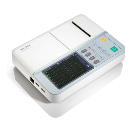
- Page 1 BeneHeart R3/BeneHeart R3A Electrocardiograph Operator’s Manual...
- Page 3 © Copyright 2013 Shenzhen Mindray Bio-Medical Electronics Co., Ltd. All rights reserved. For this Operator’s Manual, the issue date is April 2013.
- Page 4 Intellectual Property Statement SHENZHEN MINDRAY BIO-MEDICAL ELECTRONICS CO., LTD. (hereinafter called Mindray) owns the intellectual property rights to this Mindray product and this manual. This manual may refer to information protected by copyrights or patents and does not convey any license under the patent rights of Mindray, nor the rights of others.
- Page 5 Malfunction of the instrument or part whose serial number is not legible enough. Others not caused by instrument or part itself. Company Contact Manufacturer: Shenzhen Mindray Bio-Medical Electronics Co., Ltd. Address Mindray Building,Keji 12th Road South,High-tech industrial park,Nanshan,Shenzhen 518057,P.R.China Website www.mindray.com...
- Page 6 Preface Manual Purpose This manual contains the instructions necessary to operate the product safely and in accordance with its function and intended use. Observance of this manual is a prerequisite for proper product performance and correct operation and ensures patient and operator safety. This manual is based on the maximum configuration and therefore some contents may not apply to your product.
-
Page 7: Table Of Contents
Contents 1 Safety.....................................1-1 1.1 Safety Information ......................................1-1 1.1.1 Dangers ........................................1-2 1.1.2 Warnings .........................................1-2 1.1.3 Cautions ........................................1-3 1.1.4 Notes ........................................1-3 1.2 Equipment Symbols ......................................1-4 2 The Basics ..................................2-1 2.1 Intended Use........................................2-1 2.2 Main Unit ..........................................2-1 2.2.1 Front View.......................................2-1 2.2.2 Side View.........................................2-3 2.2.3 Back View ........................................2-3 2.2.4 Bottom View ......................................2-4... - Page 8 5 File Management ................................. 5-1 5.1 Accessing File Management ...................................5-1 5.2 Managing Patient Archives....................................5-1 5.2.1 Accessing the Directory Screen..............................5-1 5.2.2 Searching the Patient’s Archives..............................5-3 5.3 Managing Configuration....................................5-3 5.3.1 Loading Configuration ..................................5-3 5.3.2 Exporting Configuration...................................5-4 6 Patient Preparation ..............................6-1 6.1 Preparing a Patient ......................................6-1 6.2 Preparing the Skin ......................................6-1 6.3 Connecting Lead Wires and Electrodes ..............................6-2 6.3.1 ECG Accessories ....................................6-2...
- Page 9 9 Battery ..................................9-1 9.1 Overview ..........................................9-1 9.2 Charging the Battery......................................9-1 9.3 Replacing the Battery ......................................9-1 9.4 Battery Guidelines.......................................9-2 9.5 Battery Maintenance......................................9-3 9.5.1 Conditioning a Battery..................................9-3 9.5.2 Checking a Battery ..................................... 9-3 9.6 Battery Recycling.........................................9-4 10 Care and Maintenance ............................10-1 10.1 Cleaning and Disinfecting ..................................
- Page 10 D.6 Patient Leakage Current....................................D-3 D.7 Mains on Applied Part Leakage..................................D-4 D.8 Patient Auxiliary Current....................................D-4...
-
Page 11: Safety
Safety 1.1 Safety Information DANGER Indicates an imminent hazard that, if not avoided, will result in death or serious injury. WARNING Indicates a potential hazard or unsafe practice that, if not avoided, could result in death or serious injury. CAUTION Indicates a potential hazard or unsafe practice that, if not avoided, could result in minor personal injury or product/property damage. -
Page 12: Dangers
1.1.1 Dangers There are no dangers that refer to the product in general. Specific “Danger” statements may be given in the respective sections of this manual. 1.1.2 Warnings WARNINGS This equipment is used for single patient at a time. Before putting the system into operation, the operator must verify that the equipment, connecting cables and accessories are in correct working order and operating condition. -
Page 13: Cautions
1.1.3 Cautions CAUTIONS Use only parts and accessories specified in this manual. At the end of its service life, the equipment, as well as its accessories, must be disposed of in compliance with the guidelines regulating the disposal of such products. If you have any questions concerning disposal of the equipment, please contact us. -
Page 14: Equipment Symbols
1.2 Equipment Symbols Caution (Attention, consult ON/OFF for part of equipment accompanying documents) Battery indicator Alternating current (AC) DEFIBRILLATION-PROOF TYPE CF Equipotentiality APPLIED PART Network connector USB connector DATE OF MANUAFACTURE Serial number Environment-friendly Used Period Dispose of in accordance to your per Chinese Standard country’s requirements SJ/T11363-2006... -
Page 15: The Basics
The Basics 2.1 Intended Use BeneHeart R3/ BeneHeart R3A Electrocardiograph (hereafter referred to as “the equipment” or “the system”) is intended to acquire, analyze, display, store, and record the patient’s electrocardiographic information for clinical diagnosis and study. The equipment is intended to be used by clinical professionals or under their guidance. It must only be used by persons who have received adequate training in its use. - Page 16 Function Function key, select the option that appears at the right side of the screen. (Numerical key “1”) In numeric keypad mode, enter the number “1”. Function key, select the option that appears at the right side of the screen. (Numerical key “4”) In numeric keypad mode, enter the number “4”.
-
Page 17: Side View
Indicator Description Power indicator On: when the equipment is powered on. Off: when the equipment is powered off. Battery indicator Green: when the equipment operates on battery power or the battery is being charged. Yellow: when the equipment operates on battery power and the battery is low. Yellow, blink: when the equipment operates on battery power and the battery is depleted. -
Page 18: Bottom View
2.2.4 Bottom View Battery compartment 2.3 Display Screen Normal Screen Patient and system information area This area shows patient information including patient ID, gender, age, and heart rate, as well as system information, including Wi-Fi and USB memory connecting status, system time, battery status, and etc. Waveform area: displays ECG waveforms. -
Page 19: Operating Mode
Main Menu Heading: shows system information Options of main menu Options of submenu Function Key labels area Pressing F1 returns to previous menu. Pressing F2 and F3 selects the previous or next option, or toggles between settings when an option is selected. -
Page 20: Standby Mode
2.4.2 Standby Mode In the case that any of the limb leads is detached, the equipment automatically enters Standby Mode if there is no operation within the defined time. To set the time, Press the [Menu] key to enter the main menu. Select [System Setup]→[Auto Standby]. -
Page 21: Basic Operations
Basic Operations 3.1 Installation WARNING The equipment shall be installed by personnel authorized by us. Do not open the equipment housings. All servicing and future upgrades must be carried out by the personnel trained and authorized by our company only. The software copyright of the equipment is solely owned by us. -
Page 22: Environmental Requirements
3.1.2 Environmental Requirements The equipment is suitable for use within the patient environment. The operating environment of the equipment must meet the requirements specified in this manual. The environment where the equipment is used shall be reasonably free from noises, vibration, dust, corrosive, flammable and explosive substances. -
Page 23: Using A Battery
WARNING Use only power cord we supplied. Where the integrity of the external protective conductor in the insatllation or its arrangement is in doubt, the equipment shall be operated from the battery. Otherwise the patient or operator might be shocked. 3.2.2 Using a Battery You can run this equipment on a rechargeable lithium battery. -
Page 24: Loading Paper
3.2.3 Loading Paper Before printing ECG reports, ensure that thermal recording paper is loaded. The equipment supports both roll paper and Z-fold paper. NOTE The setting of [Paper Type] in the [System Setup] Menu must corresponds with the paper used.Otherwise, the system will prompt “Paper Type Error”. -
Page 25: Connecting The Patient Cable
To Load Z-fold paper, Press down the recorder door latch to open the recorder door. Place the Z-fold paper pack into the paper compartment. Lift the paper jam protector and click it into the little openings at the bottom of the paper roll holder. -
Page 26: Turning On The Equipment
3.2.6 Turning On the Equipment Once the equipment has been installed and checked, you can get ready for measurement and recording: Connect the equipment with AC mains. If you run the equipment on battery power, ensure that the battery is sufficiently charged. -
Page 27: System Setup
System Setup 4.1 Accessing the Main Menu Press the [Menu] key to access the main menu. Press F2 or F3 to select the desired menu item. Press F4 to confirm the selection. You can return to previous menu by pressing F1. In the main menu, you can Configure waveforms Configure recordings... -
Page 28: Wave Setup
4.2 Wave Setup Menu item Option Default Description Lead Sequence Standard, Cabrera Standard Select ECG lead sequence for displaying and recording. [Standard]: the sequence is I, II, III, aVR, aVL, aVF, V1, V2, V3, V4, V5, V6; [Cabrera]: the sequence is aVL, I, -aVR, II, aVF, III, V1, V2, V3, V4, V5, V6. -
Page 29: Record Setup
Menu item Option Default Description NOTE: BDR or 0.05-Hz selection applies to displayed ECG, printed report, and analyzed and stored data. BDR introduces around 1-second delay. We recommend use of BDR except when the delay is unacceptable. Both BDR and 0.05-Hz selections meet requirements of the 1990 American Heart Association Recommendations for Standardization and Specifications in Automated Electrocardiography:... - Page 30 Menu item Option Default Description be included in the ECG report even if enabled and you cannot set [Print Out Sequence] to [Simultaneous]. Printout Sequential, Simultaneous Sequential Set the recording method of ECG report generated Sequence by auto measurement. [Simultaneous]: Record simultaneous 12-lead ECG data.
- Page 31 Menu item Option Default Description (ms), QRSon (ms), QRSdur (ms), Qdur (ms), Rdur (ms), Sdur (ms), R'dur (ms), S'dur (ms), P+dur (ms), QRSdef (ms), P+amp (μV), P-amp (μV), QRSp2p (μV), Qamp (μV), Ramp (μV), Samp (μV), R'amp (μV), S'amp (μV), STamp (μV), 2/8STT (μV), 3/8STT (μV), T+amp (μV), T-amp (μV), QRSarea (μV*ms), Rnotch, DWconf (...
-
Page 32: File Management
Menu item Option Default Description ⎛ ⎞ HeartRate × ⎜ ⎟ ⎝ ⎠ Fridericia: ⎛ ⎞ × − ⎜ ⎟ ⎝ ⎠ HeartRate Framingham: 4.4 File Management Menu item Option Default Description Search By Date Year: 2012-2099 By selecting this option, and then setting start time and end time, you can find all the files that meet the Month: 01-12 search criteria. -
Page 33: Patient Info Setup
Menu item Option Default Description lines and 2 columns [6×2+ ]: 12-lead ECG waveforms are displayed in 6 lines and 2 columns. Additionally there is a rhythm lead at the bottom. [12×1]: 12-lead ECG waveforms are displayed in 12 lines. Record File List Print a list of all patient archives stored in the directory. -
Page 34: System Setup
Menu item Option Default Description the [patient Info] menu. 4.6 System Setup Menu item Option Default Description yyyy-mm-dd, mm-dd-yyyy, Date Format yyyy-mm-dd Select the date format. dd-mm-yyyy Time Format 12 h, 24 h 24 h Select the time format. Date Year: 2012-2099 Year: 2012 Set the current date. - Page 35 Menu item Option Default Description The equipment will not shut down if [Auto Standby] is set to [Off]. Load Import the configuration file stored in the USB Configuration memory into the equipment’s internal memory. Export Export the configuration file stored in the Configuration equipment’s internal memory to the USB memory.
- Page 36 FOR YOUR NOTES 4-10...
-
Page 37: File Management
File Management 5.1 Accessing File Management Press the [Menu] key to access the main menu. Select [File Management]. Set the options as desired. Refer to 4.4 File Management for detail. 5.2 Managing Patient Archives If you have enabled [Auto Save] in the [File Management] menu, the system automatically creates and saves a patient file at the completion of each auto measurement. - Page 38 You can view the exported PDF format files on a PC running a PDF reader. You can also print the exported reports. When printing a PDF format ECG report, properly set the printer. Taking HP LaserJet P2035n as an example, follow this procedure to set the printer: Open the PDF file to be printed.
-
Page 39: Searching The Patient's Archives
Select the [Effects] tab, and select [Actual Size]. Select [Ok] to start printing. We recommend that Adobe Reader 8.0 is used to open the PDF format ECG report. 5.2.2 Searching the Patient’s Archives The equipment has the function of searching patient archives. You can search the archives by date or by patient ID. Press the [Menu] key to access the main menu. -
Page 40: Exporting Configuration
5.3.2 Exporting Configuration You can export the configuration file stored in the equipment’s internal memory to a USB memory. Insert a USB memory into the USB connector on the left side of the equipment. Select [Menu]→[System Setup]→[Export Config]. Follow the on-screen instructions. -
Page 41: Patient Preparation
Patient Preparation Before acquiring an ECG, Prepare the patient Prepare the skin Connecting the patient cable and lead wires Place electrodes Input patient information 6.1 Preparing a Patient The following steps are necessary for patient comfort and minimizing muscle artifacts: Explain the procedure. -
Page 42: Connecting Lead Wires And Electrodes
6.3 Connecting Lead Wires and Electrodes Before acquiring the patient’s ECG, check that all electrodes are correctly connected to the lead wires and the patient cable is plugged securely into the connector on the right side of the equipment. CAUTION Ensure that the all leads are connected and all electrodes are applied to correct sites. -
Page 43: Connecting Chest Lead Wires With Chest Electrodes
Chest Electrode The chest electrode consists of a bulb and a metal electrode. On the metal electrode, there are two lead wire connectors, one for lead wire with Φ 3.0 mm connector, another for lead wire with Φ 4.0 mm connector. Bulb Lead wire connector (Φ3.0) Lead wire connector (Φ4.0) -
Page 44: Applying Electrodes
6.4 Applying Electrodes 6.4.1 Electrode Placement Electrode placement Fourth intercostal space at the right V1(C1) sternal border Fourth intercostal space at the left V4(C4) sternal border Midway between V2 (C2) and V4 (C4) V2(C2) V6(C6) electrode positions V3(C3) Fifth intercostal space at the left V5(C5) midclavicular line Left anterior axillary line, horizontal... -
Page 45: Lead Wire Colour Code
6.4.3 Lead Wire Colour Code Lead Label Colour Label Colour Right arm White Left arm Yellow Black Right leg (neutral) Black Green Left leg Green Chest 1 White/Red Brown/Red Chest 2 White /Yellow Brown /Yellow Chest 3 White /Green Brown /Green Chest 4 White /Brown Brown /Blue... -
Page 46: Applying Disposable Electrodes
Applying Chest Electrodes Check that the electrodes are clean. Connect the six chest electrodes with the chest lead wires. Route the lead wires to avoid twisting. Expose the patient’s chest. Prepare the skin as describe in 6.2 Preparing the Skin. Apply a thin layer of conductive gel on each electrode site. -
Page 47: When Lead Off Occurs
6.5 When Lead Off Occurs The system will prompt lead off when electrodes are detached, or any of the lead wires is poorly connected with the electrode, or patient cable detaches the equipment. When any of the electrodes on the patient’s left arm, left leg, or right arm is detached, or any of LA/L, LL/F, RA/R lead is off, the system will respectively prompt “LA Lead Off”(“L Lead Off”), “LLead Off”... -
Page 48: Entering Patient Information From Patient Info Screen
6.6.2 Entering Patient Information from Patient Info Screen Detailed Patient Info You can also enter patient information from the [Patient Info] screen when [ ] is enabled, see 4.5 Patient Info Setup. Press the [ID] key, or [Age] key, or [Gender] key to access the [Patient Info] menu. Input the information in the corresponding entry field. -
Page 49: Acquiring An Ecg
Acquiring an ECG WARNING This equipment is not intended to be in use with high frequency surgical units. Do not come into contact with patients during defibrillation. Otherwise serious injury or death could result. For paced patients, the equipment may mistake a pace pulse for a QRS complex if several adverse conditions exist simultaneously. -
Page 50: Rhythm Measurement
7.1.3 Rhythm Measurement In rhythm measurement mode, the equipment acquires 60 seconds of 12-lead ECG and prints the waveforms of the rhythm lead. In the rhythm ECG report, ECG waveforms are displayed in 3 cascade lines, with each line including 10 seconds of waveforms. -
Page 51: Copying An Report
7.5 Copying an Report The equipment has the function of copying the latest auto measurement report or rhythm measurement report. To print another copy of the latest auto or rhythm ECG report, press F3. You can copy the report using the current configuration, or you can also change the settings before printing another copy. -
Page 52: Ecg Report
The diagnoses of 12-lead ECG analysis is included in the ECG report by default, see the setting of [Interpretation] as described in 4.3 Record Setup. Resting 12-lead ECG analysis is not intended for the manual measurement mode and rhythm measurement mode. Refer to12-Lead ECG Interpretive Program Physician’s Guide (PN: 046-004817-00) for details. -
Page 53: Troubleshooting
Troubleshooting 8.1 General Problems This chapter lists the problems that are likely to occur. If the problem persists after corrective actions have been taken, please contact your service personnel. Symptom Possible Cause Corrective actions The equipment does not power up. 1. -
Page 54: Messages
Partially missing printout or printout 1. Dirty print head. 1. Clean the print head. not clear. 2. Some thermal points on print head 2. If the problem persists, contact your are damaged. service personnel. The equipment automatically shuts 1. Auto shutdown is enabled. 1. -
Page 55: Message List 1
8.2.1 Message List 1 Message Trigger Action Battery depleted! The battery is too low. Connect the equipment to AC mains to run the equipment and charge the battery. Recorder unavailable! 1. When recording is needed or a 1. Verify that recording paper is measurement is started. -
Page 56: Prompt Message List 2
Message Trigger Action Configuration is successfully exported. Export configuration successfully Export failed Exporting patient data failed. 1. Check that the settings are correct and a correct option is select. 2. Check that USB memory is properly inserted and file system is not damaged. - Page 57 Message Trigger Action equipment. 2. Check that patient cable is properly connected to the equipment. XX Lead off The referred lead is off. Check corresponding electrodes and lead wires. Re-apply the electrodes or (XX refers to LA/L, LL/F, V1-V6/C1-C6) reconnect the lead wires if necessary. Noise Noise or artifacts from lead I, II, V1, V2, Check the patient.
- Page 58 FOR YOUR NOTES...
-
Page 59: Battery
Battery 9.1 Overview The equipment is designed to operate from battery power during intra-hospital patient transfer or whenever AC power supply is not available. The equipment uses AC power as primary power source. In case of power failure, the equipment will automatically run power from the battery. -
Page 60: Battery Guidelines
9.4 Battery Guidelines Life expectancy of a battery depends on how frequent and how long it is used. For a properly maintained and stored lithium ion battery, its life expectancy is about 3 years. For more aggressive use models, life expectancy can be less. We recommend replacing lithium ion batteries every 3 years. -
Page 61: Battery Maintenance
9.5 Battery Maintenance 9.5.1 Conditioning a Battery A battery should be conditioned before it is used for the first time. A battery conditioning cycle is one uninterrupted charge of the battery, followed by an uninterrupted battery discharge and charge. Batteries should be conditioned regularly to maintain their useful life. -
Page 62: Battery Recycling
9.6 Battery Recycling A battery should be replaced if there are visual signs of damage, the battery fails, or the battery has been used for more than three years. To dispose of the batteries, follow local laws for proper disposal. WARNING Do not disassemble, puncture or incinerate batteries. -
Page 63: Care And Maintenance
Care and Maintenance Regular maintenance is essential to ensure that the equipment functions properly. This chapter contains information on basic care and periodic maintenance. WARNING Failure for the responsible individual, hospital or institution employing this equipment to implement a satisfactory maintenance schedule may cause undue equipment failure and possible health hazards. The safety checks or maintenance involving any disassembly of the equipment should be performed by professional servicing personnel. -
Page 64: Cleaning
10.1.1 Cleaning Recommended cleaning agents for the equipment are: sodium hypochlorite bleach (diluted) Hydrogen peroxide (3%) Ethanol (75%) Isopropanol (70%) To clean the accessories, we recommend you to use ethanol (75%). Cleaning the equipment Your equipment should be cleaned on a regular basis. If there is heavy pollution or lots of dust and sand in your place, the equipment should be cleaned more frequently. -
Page 65: Disinfecting
Cleaning Reusable Electrodes Clean reusable electrodes immediately after use on a patient. Gently wipe the electrodes surface with a soft cloth dampened with ethanol 75%, avoiding the metal connectors. Wipe off excess moisture with a dry cloth. Dry the electrodes in a ventilated, cool place. Cleaning Thermal Print head Dirty print head will deteriorate printing quality. -
Page 66: Regular Check
10.2 Regular Check Perform a visual inspection before the equipment’s first use everyday. In case of any damage or abnormity, remove the equipment from use. Contact the hospital’s biomedical engineers or your service personnel immediately. Verify that the equipment meets the following requirements: The housing and display screen are free from cracks and other damages. -
Page 67: Storing Thermal Recording Paper
10.4 Storing Thermal Recording Paper To store thermal paper, follow these rules: Store in a cool, dark, and dry place, avoiding high temperature, moisture and direct sunlight. Avoid long-term exposure to fluorescent. Do not store thermal paper with polyvinyl chloride or other chemicals which cause yellowing and fading. Do not overlap used thermal paper for a long time. - Page 68 FOR YOUR NOTES 10-6...
-
Page 69: Accessories
Accessories WARNING Use accessories specified in this chapter. Using other accessories may cause damage to the equipment or not meet the claimed specifications. Single-use accessories are not designed to be reused. Reuse may cause a risk of contamination and affect the measurement accuracy. - Page 70 FOR YOUR NOTES 11-2...
-
Page 71: A Product Specifications
Product Specifications A.1 Classifications The equipment is classified, according to IEC60601-1: CLASS I EQUIPMENT, equipment energized from an external and internal Type of protection against electrical shock electrical power source. Degree of protection against electrical DEFIBRILLATION-PROOF TYPE CF AAPPLIED PART shock Mode of operation CONTINUOUS OPERATION... -
Page 72: Power Supply Specifications
A.3 Power Supply Specifications AC power Input voltage 100-240V~ (±10%) Input power 60 VA Frequency 50 Hz/60 Hz (±3 Hz) Fuse T2A 250V Battery Battery Type Rechargeable lithium-ion battery ℃ ℃, When powered by a new fully-charged battery and at ambient temperature 25 ±5 Run time ≥500 auto measurement reports, or 2 hours of continuous recording, or 6 hours of... -
Page 73: Hardware Specifications
A.5 Hardware Specifications A.5.1 Display Screen type Colour TFT LCD Screen Size 5 inch Resolution 800×480 pixels A.5.2 Equipment Connector 1, connects patient cable for ECG acquisition Patient cable connector 2, connects USB disc for data transfer USB connector Network connector 1, standard RJ45 connector, connects the equipment to the network for software upgrade A.5.3 Indicators Power indicator... -
Page 74: Measurement Specifications
A.6 Measurement Specifications Standards IEC 60601-2-25, IEC 60601-2-51, EC11 Measurement mode Auto, manual, rhythm Lead type 12-lead ECG standard AHA, IEC 2.5 mm/mV, 5 mm/mV, 10 mm/mV, 20 mm/mV, Auto ECG size Accuracy: ±5% 5 mm/s, 12.5 mm/s, 25 mm/s, 50 mm/s Sweep speed Accuracy: ≤±5% Baseline drift removal (BDR) - Page 75 ≤0.5mm at normal sensitivity Channel crosstalk Measuring electrode: ≤0.1 μA Lead-off detection current Drive electrode: ≤1 μA Minimum signal 10Hz sinusoidal signal, with 20μVp-p deflection Baseline drift ≤1 mm, Baseline stability Average baseline drift ≤0.5mm/℃ within operation temperature range Pace pulse Pace pulses meeting the following conditions are labelled with a PACE marker: ±2 mV-±250 mV Amplitude:...
- Page 76 FOR YOUR NOTES...
- Page 77 The device meets the requirements of IEC 60601-1-2. Note Using accessories, transducers and cables other than those specified may result in increased electromagnetic emission or decreased electromagnetic immunity of the patient monitoring equipment. The device or its components should not be used adjacent to or stacked with other equipment. If adjacent or stacked use is necessary, the device or its components should be observed to verify normal operation in the configuration in which it will be used.
- Page 78 Guidance and Declaration - Electromagnetic Immunity The device is intended for use in the electromagnetic environment specified below. The customer or the user of the device should assure that it is used in such an environment. Electromagnetic environment - Immunity test IEC60601 test level Compliance level guidance...
- Page 79 Guidance and Declaration - Electromagnetic Immunity The device is intended for use in the specified electromagnetic environment. The customer or the user of the device should assure that it is used in such an environment as described below. Immunity test IEC60601 test Compliance Electromagnetic environment - guidance...
- Page 80 Recommended separation distances between portable and mobile RF communications equipment and the device The device is intended for use in an electromagnetic environment in which radiated RF disturbances are controlled. The customer or the user of the device can help prevent electromagnetic interference by maintaining a minimum distance between portable and mobile RF communications equipment (transmitters) and the device as recommended below, according to the maximum output power of the communications equipment.
-
Page 81: C Symbols And Abbreviations
Symbols and Abbreviations C.1 Units μA microampere μV microvolt μs Microsecond ampere ampere hour beat per minute bit per second ºC centigrade centimeter decibel ºF fahrenheit gram gigahertz hour hertz inch kilo kilogram kilopascal litre meter milliampere hour mega byte milligram minute milliliter... -
Page 82: Symbols
millisecond millivolt milliwatt MΩ megaohm second volt volt ampere Ω watt C.2 Symbols - minus – negative percent per; divide; or + plus = equal to < less than > greater than ≤ less than or equal to ≥ greater than or equal to ±... -
Page 83: Abbreviations And Acronyms
C.3 Abbreviations and Acronyms Association for Advancement of Medical AAMI Instrumentation alternating current adult American Heart Association ANSI American National Standard Institute left foot augmented lead left arm augmented lead right arm augmented lead cardiac (coronary) care unit Conformité Européenne clinical information system CISPR International Special Committee on Radio... - Page 84 liquid crystal display light emitting diode left leg Medical Device Directive magnetic resonance imaging not applied neonate operating room pediatric right right arm record, recording right leg uninterruptible power supply universal serial bus volts alternating current...
-
Page 85: D Electrical Safety Inspection
Electrical Safety Inspection The following electrical safety tests are recommended as part of a comprehensive preventive maintenance program. They are a proven means of detecting abnormalities that, if undetected, could prove dangerous to either the patient or the operator. Additional tests may be required according to local regulations. All tests can be performed using commercially available safety analyzer test equipment. -
Page 86: Device Enclosure And Accessories
D.2 Device Enclosure and Accessories D.2.1 Visual Inspection Test Item Acceptance Criteria No physical damage to the enclosure and accessories. No physical damage to meters, switches, connectors, etc. The enclosure and accessories No residue of fluid spillage (e.g., water, coffee, chemicals, etc.). -
Page 87: Earth Leakage Test
D.5 Earth Leakage Test Run an Earth Leakage test on the device being tested before performing any other leakage tests. The following outlet conditions apply when performing the Earth Leakage test. normal polarity( Normal Condition), reverse polarity( Normal Condition), normal polarity with open neutral(Single Fault Condition), reverse polarity with open neutral(Single Fault Condition) LIMITS For UL60601-1,... - Page 88 D.7 Mains on Applied Part Leakage The Mains on Applied Part test applies a test voltage, which is 110% of the mains voltage, through a limiting resistance, to selected applied part terminals. Current measurements are then taken between the selected applied part and earth. Measurements are taken with the test voltage (110% of mains) to applied parts in the normal and reverse polarity conditions The following outlet conditions apply when performing the Mains on Applied Part test.
- Page 90 PN: 046-004651-00 (2.0)
Need help?
Do you have a question about the BeneHeart R3 and is the answer not in the manual?
Questions and answers