
Summary of Contents for Keymile COGE5
- Page 1 User Manual COGE5, COGE5-F co5ne_r2b, co5un_r2b Control, 10 Gb Ethernet switch, uplinks, sync XMC20...
- Page 2 Copyright and Confidentiality Copyright in this document vests in KEYMILE. This document contains confi- dential information which is the property of KEYMILE. It must be held in con- fidence by the recipient and may not be used for any purposes except those specifically authorised by contract or otherwise in writing by KEYMILE.
-
Page 3: Table Of Contents
Symbols and Notations Interfaces and Circuit Categories Document History Target audience Definition of Terms Introduction General Unit View Block Diagram Specification Feature Licences COGE5 Function Overview COGE5-F Function Overview Versions Installation Prerequisites Slots Compatibility Connections and Cables Functional Description Applications Interfaces Equipment Protection EQP (Core Unit Redundancy) ©... - Page 4 User Manual COGE5, COGE5-F Synchronization Commissioning Commissioning Prerequisites for COGE5 First ESW Download to a COGE5 Unit Configuring an Ethernet Front Port Commissioning MPLS-TP Commissioning the PTP synchronization Operation and Maintenance Unit Optical Indicators Maintenance Unit and Network Element ESW Download...
- Page 5 User Manual COGE5, COGE5-F Product Training © KEYMILE December 2015 page 5 of 110 EN/LZTBU 372 144/3 RA...
- Page 6 XMC20 subracks with core unit COGE5 in slot 11 Figure 5: XMC20 subracks with core unit COGE5 in slot 11 & redundant core unit COGE5 in slot 13 Figure 6: COGE5 (left) and COGE5-F (right) front panel and interface connectors...
-
Page 7: Preface
Indicates that an action may lead to operating trouble or loss of data. → Possible actions are given. Please note: Shows significant information. → Possible actions are given. © KEYMILE December 2015 page 7 of 110 EN/LZTBU 372 144/3 RA... -
Page 8: Interfaces And Circuit Categories
1550 nm a. The listed optical properties are related to the SFPs plugged in the COGE5 unit. b. As the laser protection class 1 is complied, dangerous radiation cannot be emitted. Thus, special precautions for failures or laser warnings are not necessary. -
Page 9: Document History
Term Explanation COGE5 The COGE5 is the one slot wide core and control unit of the XMC25, the XMC23 and the XMC22. It must be operated in an actively cooled XMC20 subrack. In this user guide, the term COGE5 is used to name the COGE5 and COGE5-F. -
Page 10: Introduction
XMC20”. XMC20 TDM traffic architecture and functions for PDH and SDH. The COGE5 is the 1 slot wide core and control unit for the multiservice access nodes XMC25, XMC23 and XMC22, that must be operated in actively cooled subracks. The COGE5-F is a 2 slot wide functional equiva- lent to the COGE5 unit that can be operated in passively cooled subracks. -
Page 11: Figure 1: Coge5 Unit Application With A Subtending Xmc20
11 by insert- ing and configuring a second control unit in slot 13. The details described in this document base on a specific COGE5 or COGE5-F embedded software (ESW) version. For more details about the... -
Page 12: Unit View
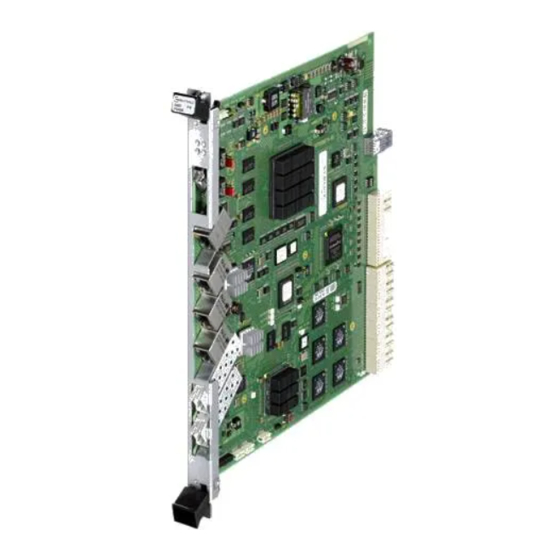
2 "COGE5 (left) and COGE5-F (right) unit view" shows the COGE5 and COGE5-F units with their front panels and interfaces. On the front plate are four LEDs for unit- and traffic status indication. Non-observance could result in minor or moderate injury. -
Page 13: Block Diagram
Introduction User Manual COGE5, COGE5-F Block Diagram The figure below shows the functional block diagram of the COGE5 unit. For more information regarding these functions, please refer to section 5 Func- tional Description (on page 31). 1 … 5 20x1GbE... -
Page 14: Specification
Specification User Manual COGE5, COGE5-F Specification The COGE5 unit uses the following feature licences, provides the functions listed below and conforms to the corresponding standards and recommenda- tions (conformance to applicable parts of the standards). Feature Licences This unit is subject to one or several feature licences. The following licences are available for this unit. -
Page 15: Coge5 Function Overview
Specification User Manual COGE5, COGE5-F COGE5 Function Overview The COGE5 unit provides the following functions and supports the following standards: Table 6: COGE5 Function Overview - system features Feature Rating or standard Release Central management point for the XMC25 network ele-... - Page 16 16 Mbit/s total - Number of MPLS interfaces a. The recommended SFP+ and SFP module types are listed in the KEYMILE Technical Bulletin “Supported SFP Trans- ceivers”. Please refer to section 4.4.2 SFP+ 10GbE optical Modules and Cables (on page 25) and section 4.4.3 SFP...
- Page 17 QoS Priority scheduler, - Strict priority - Shaped Deficit Weighted Round Robin a. The recommended SFP+ and SFP module types are listed in the KEYMILE Technical Bulletin “Supported SFP Trans- ceivers”. Please refer to section 4.4.2 SFP+ 10GbE optical Modules and Cables (on page 25) and section 4.4.3 SFP...
- Page 18 Specification User Manual COGE5, COGE5-F Table 11: COGE5 Function Overview - other standards (continued) Feature Rating or standard Release Safety refer to [201] System Description “XMC20 R6B” SFP/SFP+ modules: according to the manufacturer’s data sheets (typi- cally IEC 60825-1 Class 1 laser product)
-
Page 19: Coge5-F Function Overview
Specification User Manual COGE5, COGE5-F COGE5-F Function Overview The COGE5-F unit provides the same functions and supports the same standards as the COGE5 unit, with the following exceptions: Table 12: COGE5-F Function Overview - equipment features Feature Rating or standard... -
Page 20: Installation
[302] User Guide “XMC25/XMC23/ XMC22” For a specific description of the ESW download and assignment to a COGE5 unit which is already in service or to a redundant COGE5 unit please refer to section 7.3 Unit and Network Element ESW Download (on page 60). -
Page 21: Slots
User Manual COGE5, COGE5-F Slots For XMC20 systems with only one COGE5 unit, this unit must be placed in slot 11, as shown in Figure 4 "XMC20 subracks with core unit COGE5 in slot 11". All other slots can be equipped with service units (SU). - Page 22 Slot Slot Slot Slot Slot Slot Slot Slot Slot Figure 5: XMC20 subracks with core unit COGE5 in slot 11 & redundant core unit COGE5 in slot 13 © KEYMILE December 2015 page 22 of 110 EN/LZTBU 372 144/3 RA...
-
Page 23: Compatibility
Installation User Manual COGE5, COGE5-F Compatibility 4.3.1 XMC20 Units COGE5 is compatible with any other XMC20 unit with an ESW release of the current XMC20 system release. Please refer to [012] Release Note “XMC20 System Release R6B”. 4.3.2 Previous ESW Revisions The COGE5 unit with ESW release co5xx_r2b is compatible to the previous XMC20 system release R6A. -
Page 24: Connections And Cables
User Manual COGE5, COGE5-F Connections and Cables 4.4.1 Front Connector of the COGE5 Unit The COGE5 front panel connections are implemented as shown in Figure "COGE5 (left) and COGE5-F (right) front panel and interface connectors". Fixing screw Pull-out handle with... -
Page 25: Figure 7: Ethernet Link Leds On The Electrical Ethernet Interfaces
For details on connectors and pins for this interface, please refer to [SFF- 8431]. SFP+ DDM (Digital Diagnostic & Monitoring) is supported on the SFP+ mod- ules that are plugged in the SFP cages of the COGE5 unit provided that the module itself is supporting this feature. © KEYMILE December 2015... - Page 26 8074]. SFP DDM (Digital Diagnostic & Monitoring) is supported on the SFP mod- ules that are plugged in the SFP cages of the COGE5 unit provided that the module itself is supporting this feature. The optical 1GbE interfaces (SFP modules) are equipped with industry standard duplex LC connectors.
- Page 27 Please note: With auto negotiation switched off, a crossed cable has to be used to con- nect to another COGE5 since the interface cannot automatically select the mode. The following table shows the behaviour of COGE5 when connecting an...
- Page 28 4.4.6 Cable Fixing In the XMC25, cables connecting to the COGE5 unit or other units in general should be guided and attached to the cable tray as indicated in Figure "Side view of the subrack including cabling and cable tray".
-
Page 29: Figure 8: Side View Of The Subrack Including Cabling And Cable Tray
Figure 8: Side view of the subrack including cabling and cable tray In the XMC23 and XMC22, cables connecting to the COGE5 unit or other units should be guided and attached similarly to the way shown in Figure "Side view of the subrack including cabling and cable tray"... - Page 30 Ethernet cables to the traffic interfaces For maximum protection against failures, also electrical and optical cables from a switching or routing device to ports 1 to 5 of the COGE5 unit need to be connected to both units, the working and the standby COGE5.
-
Page 31: Functional Description
5.1.1 Hardware Control One of the main functions of the COGE5 unit is to control the service units at hardware level. This comprises the following functions: • Check the presence of service units •... - Page 32 XMC20 Switch or connecting Ethernet switch devices not being part of the XMC20 Switch. The COGE5 unit has also two internal ports of 10 Gbit/s connecting a redun- dant COGE5 unit. COGE5 permits switching traffic at wire speed between all its ports.
- Page 33 Functional Description User Manual COGE5, COGE5-F The following table summarises the main features of the COGE5 switch cir- cuit. Table 16: COGE5 switch features Feature Details Generic Main feature L2 switching No. of ports Internal packet buffer 1.5 MB MAC addresses up to 16’000...
- Page 34 A VPWS connects the Pseudo Wire Access Circuit (PWAC) ports to the MPLS-TP uplink ports. The PWAC ports are located on Ethernet service units or on the COGE5 unit, the MPLS-TP uplink ports are the external Ethernet interfaces of the COGE5 unit.
-
Page 35: Security Features
[358] User Manual “MPLS-TP”. 5.1.6 Security Features Security features as e.g. ingress storm control are features of the XMC20 Switch. Please refer to [201] System Description “XMC20 R6B”. © KEYMILE December 2015 page 35 of 110 EN/LZTBU 372 144/3 RA... -
Page 36: Interfaces
External alarms 5.2.1 Traffic Ports Traffic ports are the five Ethernet front ports of the COGE5. Traffic ports are part of the XMC20 Switch. For the VLAN Bridge application the port type of traffic ports must be config- ured to “CVP”, i.e. Customer VLAN Port. With this the ports can be config- ured to be •... - Page 37 MPLS-TP port. Please note: A COGE5 unit cannot be unassigned while at least one port is configured as PWAC port and used for a pseudo wire (VPWS), or configured as MPLS-TP port and used for a tunnel.
-
Page 38: Management Ports
5.2.3 Mirror Ports Any of the five Ethernet front ports of the COGE5 unit, and any other Ether- net port of the XMC20 Switch, can be configured to be a mirror port. In this case, frames from any other front port can be copied to this port. -
Page 39: Figure 9: Jumper Position And Setting For Esi-1 And Esi-2
Figure 9: Jumper position and setting for esi-1 and esi-2 The eso-1 and/or eso-2 output are only active on the active COGE5 unit and if the eso-1 and/or eso-2 output is not squelched. The impedance of an active output interface is 120 Ohm, the impedance of a squelched or disabled output on the standby COGE5 unit is “high”. - Page 40 PBUS The PBUS contains signals for synchronization, distribution of PDH signals, and internal communication. COGE5 and all service units have access to the PBUS in order to exchange information using the KEYMILE proprietary protocol ICN (Internal Communi- cation Network). The ICN is used for the management communication between the core unit and service units within the subrack.
-
Page 41: Equipment Protection Eqp (Core Unit Redundancy)
13 of the XMC25 or XMC23 subrack. For the redundant core unit installation procedure please refer to section 7.3.4 ESW Download on a redundant COGE5 Unit plugged in the first Time (on page 64). Please note:... -
Page 42: Synchronization
User Guide “TDM Services and Cross Connections in XMC20”. At COGE5 level, you can define the esi-1, esi-2 labels (Label 1, Label 2, and Description). In addition, in case of loss of signal, this port will generate an alarm from this access point. -
Page 43: Figure 11: Pets Synchronization With Synchronous Ethernet
COGE5, COGE5-F Please note: Only two of the three electrical Ethernet interfaces port-3 to port-5 on the COGE5 unit can be selected as synchronous Ethernet source at the same time. Risk of operating trouble! An electrical SFP based Ethernet port does not support synchronous Ether- net. - Page 44 10GBASE-x. Risk of operating trouble! The SFP-based 1 GbE interfaces port-1 and port-2 on the COGE5 unit are not operable as PTP timing sources. → The port-1 and port-2 must use the 10 GbE mode to be usable as PTP timing source.
-
Page 45: Figure 12: Pets Synchronization With Ptp, Boundary Clock
And Time - Time Sources) if the PTP is enabled and at least one PTP source is selected as PETS clock source. The PTP mode must be config- ured to “Frequency And Phase”, to “Hybrid” or to “Pure Hybrid”. © KEYMILE December 2015 page 45 of 110 EN/LZTBU 372 144/3 RA... -
Page 46: Figure 13: Ptp Boundary Clock
Master PTP mode: Ordinary/Boundary Clock Figure 13: PTP Boundary Clock For a Boundary Clock network element the XMC20 and the COGE5 have to be configured as follows: • COGE5, AP: /unit-x, Configuration - PTP - Clock Type: − Boundary Clock. -
Page 47: Figure 14: Ptp Ordinary Clock
Front port-x PTP port role: Slave Figure 14: PTP Ordinary Clock For an Ordinary Clock network element the XMC20 and the COGE5 have to be configured as follows: • COGE5, AP: /unit-x, Configuration - PTP - Clock Type: − Boundary Clock. -
Page 48: Figure 15: Ptp Transparent Clock
Master PTP mode: Transparent Clock Figure 15: PTP Transparent Clock For a Transparent Clock network element the XMC20 and the COGE5 have to be configured as follows: • COGE5, AP: /unit-x, Configuration - PTP - Clock Type: − Disabled (preferred). - Page 49 − Master Or Slave (for ports for which the role can change when the synchronization path direction changes). • COGE5, AP: /unit-x/port-y, Overview - Port Type - Usage: − CVP. • ECST “Switching” view, Switching - Bridging - bridge-1 - Ports: −...
-
Page 50: Commissioning
R6B”. Please note: When you power up the COGE5 unit for the first time (from factory default settings), all LEDs will be “ON”. This state means that the network element bootloader is active but there is no application software (ESW) to launch. - Page 51 Guide “Management Communication”. For a specific description of the ESW download and assignment to a COGE5 unit which is already in service or to a redundant COGE5 unit please refer to section 7.3 Unit and Network Element ESW Download (on page 60).
-
Page 52: First Esw Download To A Coge5 Unit
When inserting a COGE5 unit the first time into a XMC20 subrack the unit is running in the network element bootloader, no ESW is installed. You need to install valid ESW on the COGE5 unit in slot 11. If you implement core unit redundancy, you need to install the identical ESW on the COGE5 units in both slot 11 and slot 13. -
Page 53: Configuring An Ethernet Front Port
COGE5, COGE5-F Configuring an Ethernet Front Port In order to configure one of the Ethernet front ports in COGE5, the following steps have to be performed. If you are using a redundant COGE5, the steps must be performed on both COGE5, the active core unit (unit-11) and the standby core unit (unit-13). - Page 54 3. Add the VLAN 100: Click the “Create” button. The “Create a new VLAN” dialogue opens. 4. Enter the VLAN parameters: VLAN ID = 100. Name = VLAN_100. Click the “OK” button. © KEYMILE December 2015 page 54 of 110 EN/LZTBU 372 144/3 RA...
- Page 55 The port is activated. Save the configuration Proceed as follows: 1. Save the configuration to the NE flash memory: Execute “Save to NE”. Result: The configuration is saved. End of instruction © KEYMILE December 2015 page 55 of 110 EN/LZTBU 372 144/3 RA...
-
Page 56: Commissioning Mpls-Tp
AP: /unit-11/port-y or /unit-13/port-y, Configuration - PTP. An example for the “Hybrid” network element synchronization, using PTP and synchronous Ethernet, is described in [314] User Guide “TDM Services and Cross Connections in XMC20”. © KEYMILE December 2015 page 56 of 110 EN/LZTBU 372 144/3 RA... -
Page 57: Operation And Maintenance
COGE5, COGE5-F Operation and Maintenance This section presents how to operate the COGE5 unit once it has been com- missioned. For a description on how to configure and bring into operation the COGE5 unit and its main functions, refer to section 6 Commissioning page 50). - Page 58 - In the waiting state the control unit is waiting for configuration. The waiting state lasts as long as the COGE5 has no configura- tion. In this state, the COGE5 can only provide the “point to point” type of management communication. This means that only the Ethernet local management port will allow a direct connection for initial commissioning.
-
Page 59: Maintenance
Operation and Maintenance User Manual COGE5, COGE5-F Maintenance 7.2.1 Inventory Data It is possible to read inventory data from the COGE5 unit via the ECST at the following access points: • AP: /unit-x, Main - Inventory, for unit related information, and •... -
Page 60: Unit And Network Element Esw Download
Risk of operating trouble! The assignment of new unit ESW or network element ESW to COGE5 requires a restart of the unit. → Thus, the installation of new ESW on the COGE5 unit affects all traffic functions. Risk of operating trouble! An ESW upgrade may perform also a firmware upgrade which will take about 30 s. - Page 61 10. Save the configuration to the NE flash memory: Execute “Save to NE”. 11. Start the new unit software. In the MF “Main” of the AP: /unit-11, i.e. the COGE5 unit, click the command button “Start Software”. This reboots the unit ESW of the control unit.
- Page 62 6. Save the configuration to the NE flash memory: Execute “Save to NE”. 7. Start the new software. In the MF “Main” of the AP: /unit-11, i.e. the COGE5 unit, click the command button “Start Software”. This reboots the unit ESW of the control unit.
- Page 63 ESW (co5ne_rxxxx). 3. Open the MF “Main” and select the tab “Software”. Select the new COGE5 NE ESW (co5ne_r2bxx) in the list of “Soft- ware On Element Manager” and click “Download”. Wait until the download is terminated and the ESW appears in the list “Software On Unit”.
- Page 64 COGE5 - the ECST accesses the above mentioned access points. - the active COGE5 unit is plugged in slot 11, the redundant COGE5 unit is plugged in slot 13. The following actions must be performed to download and start the ‒...
- Page 65 7.3.5 Set the COGE5 Unit into the Network Element Bootloader Please note: Setting the active COGE5 unit into the bootloader while there is a standby COGE5 available, the standby COGE5 will take over the active role. Risk of operating trouble! Please be aware of the fact, that a core unit in the bootloader can only be accessed locally via the Ethernet local management port.
- Page 66 The COGE5 unit is assumed to be plugged in slot 11. Set to the unit bootloader The following actions must be performed to bring a running COGE5 unit into the unit (UN) bootloader. Bootloader procedure Proceed as follows: 1.
- Page 67 The AP: /unit-11 is now running in the network element bootloader (bco5n_rxxxx). 5. Open the MF “Main” and select the tab “Software”. If the desired NE ESW is not available on the unit select the COGE5 NE ESW (co5ne_r2bxx) in the list of “Software On Element Manager” and click “Download”.
-
Page 68: Setting Up Mirror Ports
Assuming the case where you want to mirror all frames that are sent by the port-1 of a service unit in slot 20 to the COGE5 unit, and you have one front port of the COGE5 yet unused (e.g. port-5), you may proceed as follows to get the frames to a monitoring equipment connected to that spare front port. -
Page 69: Mpls-Tp Status
Operation and Maintenance User Manual COGE5, COGE5-F Now you connect your monitoring equipment to port-5 of the COGE5 unit and start monitoring. MPLS-TP Status The management functions for the operation of MPLS-TP are located in the ECST tab “MPLS-TP”. For a description of this functionality please refer to [358] User Manual “MPLS-TP”. -
Page 70: User Interface Reference
User Manual COGE5, COGE5-F User Interface Reference This section gives a complete reference of the managed objects, properties, and commands of the COGE5 core unit as far as these are not covered in the generic descriptions in [302] User Guide “XMC25/XMC23/XMC22”. - Page 71 The iports AP contains all internal Ethernet ports. iport-b Management of the Ethernet internal ports. The internal ports connect all service units with the core unit COGE5 and connect the working and redundant core units when using equipment protection. The detailed properties are described in section 8.9 AP: / unit-x...
- Page 72 Please note: Screenshots presented in this reference are examples and show configura- tions or data that may not correspond to the view you see when managing your XMC20 equipment. © KEYMILE December 2015 page 72 of 110 EN/LZTBU 372 144/3 RA...
-
Page 73: Ap: / Unit-X: Coge5
The name “unit-x” stands for: • the “unit-11” if only one COGE5 is operated in the XMC20, or • the “unit-13” if, in addition to unit-11 a redundant COGE5 is operated in the XMC20. 8.2.1 AP: / unit-x, Overview For a description of the −... - Page 74 Descriptions / Details Clock Config Clock Type Disabled The COGE5 unit is not used as a PTP ordinary or boundary clock. It can be used as a PTP transparent clock. No PTP port can be used as PETS timing source.
- Page 75 8.2.5.1 AP: / unit-x, QoS – Rate Limiting For a description of the − “QoS - Rate Limiting” management function, please refer to [302] User Guide “XMC25/XMC23/ XMC22”. © KEYMILE December 2015 page 75 of 110 EN/LZTBU 372 144/3 RA...
-
Page 76: Ap: / Unit-X / Port-A
The COGE5 front Ethernet ports (port-a) are used for the connection of external equipment. Please note: The local management port on the COGE5 unit is part of the management interfaces and is described in [323] User Guide “Management Communica- tion”. - Page 77 8.3.2.2 AP: / unit-x / port-a, Main – SFP The Main - SFP management function is only available for the SFP based ports: • port-1, and • port-2. © KEYMILE December 2015 page 77 of 110 EN/LZTBU 372 144/3 RA...
- Page 78 Manufacturing Date 0 … 10 characters Manufacturer ID 0 … 16 characters Manufacturer Part 0 … 16 characters Number © KEYMILE December 2015 page 78 of 110 EN/LZTBU 372 144/3 RA...
- Page 79 1 Gbit/s, full duplex (for SFP modules only). The <xx> string designates the SFP type, e.g. 10GigBase<xx> 10 Gbit/s, full duplex (for SFP+ modules only). The <xx> string designates the SFP type, e.g. © KEYMILE December 2015 page 79 of 110 EN/LZTBU 372 144/3 RA...
- Page 80 Please note: For an overview on the specific characteristics of XMC20 Switch ports, please refer to [356] User Manual “Ethernet Switching” and refer to [358] User Manual “MPLS-TP”. © KEYMILE December 2015 page 80 of 110 EN/LZTBU 372 144/3 RA...
- Page 81 Channel (ESMC) for the transport of the syn- chronization status message (SSM). The PETS QL value is only transmitted if the COGE5 unit configuration parameter “Synchro- nized To NE Clock Enabled” is set to true. Other- wise the transmit timing is free running and the transmitted QL is “Do Not Use”.
- Page 82 → A 1000BASE-T Ethernet port transports timing information only from the clock master to the clock slave. Risk of operating trouble! An Ethernet port operating in 10BASE-T mode cannot be used for the syn- chronous Ethernet. © KEYMILE December 2015 page 82 of 110 EN/LZTBU 372 144/3 RA...
- Page 83 For more information regarding quality level handling please refer to [314] User Guide “TDM Services and Cross Connections in XMC20”. 8.3.3.2 AP: / unit-x / port-a, Configuration – PTP © KEYMILE December 2015 page 83 of 110 EN/LZTBU 372 144/3 RA...
- Page 84 Enter the MAC address of the remote Ethernet port (Master) when using the unicast addressing scheme. Default: A0:00:00:00:00:01 Forward Multicast Forwarding of multicast messages is required if Messages the grand master clock generates multicast frames. © KEYMILE December 2015 page 84 of 110 EN/LZTBU 372 144/3 RA...
- Page 85 Risk of operating trouble! The SFP-based 1 GbE interfaces port-1 and port-2 on the COGE5 unit are not operable as PTP timing sources. → The port-1 and port-2 must use the 10 GbE mode to be usable as PTP timing source.
- Page 86 User Interface Reference User Manual COGE5, COGE5-F Please note: A COGE5 port is only selectable as PTP source if the COGE5 is configured correspondingly: → AP: /unit-x, Configuration - PTP: Clock Type = Ordinary Clock, or Boundary Clock. → AP: /unit-x/port-y, Configuration - PTP: PTP Mode = Ordinary/Boundary Clock.
- Page 87 100BASE-TX and optical port types have the Slave Role always enabled. Please note: For more information regarding quality level handling please refer to [314] User Guide “TDM Services and Cross Connections in XMC20”. © KEYMILE December 2015 page 87 of 110 EN/LZTBU 372 144/3 RA...
- Page 88 PTP slave clock. The “Unknown” QL is sent if the port is a trans- parent port. 1 … 14 Display of the transmitted QL value < 15. © KEYMILE December 2015 page 88 of 110 EN/LZTBU 372 144/3 RA...
- Page 89 UTC day contains 61 seconds. Time Traceable The parameter is true if the timescale and the value of “Current UTC Offset” are traceable to a primary reference. © KEYMILE December 2015 page 89 of 110 EN/LZTBU 372 144/3 RA...
- Page 90 (master to slave), i.e. on a Master port. Please note: The received QL value displayed is only meaningful in the forward direction of synchronization (master to slave), i.e. on a Slave port. © KEYMILE December 2015 page 90 of 110 EN/LZTBU 372 144/3 RA...
- Page 91 Number of egress broadcast packets TX Errors 0 … 2 Number of egress errored packets Please note: The statistics counters restart with 0 when they reach their upper range limit. © KEYMILE December 2015 page 91 of 110 EN/LZTBU 372 144/3 RA...
- Page 92 User Interface Reference User Manual COGE5, COGE5-F 8.3.6.2 AP: / unit-x / port-a, Statistics – Ethernet © KEYMILE December 2015 page 92 of 110 EN/LZTBU 372 144/3 RA...
- Page 93 These counters are not available for 10 GbE interfaces. They are always 0. Please note: The statistics counters restart with 0 when they reach their upper range limit. © KEYMILE December 2015 page 93 of 110 EN/LZTBU 372 144/3 RA...
- Page 94 → First configure the port type to PWAC or to CVP. For a description of the − “QoS - Rate Limiting” management function, please refer to [302] User Guide “XMC25/XMC23/ XMC22”. © KEYMILE December 2015 page 94 of 110 EN/LZTBU 372 144/3 RA...
-
Page 95: Ap: / Unit-X / Port-A / Mau
The plugged SFP/SFP+ module is not With Configuration Alarm compatible with the unit configuration HW stored in the database. You may need to change the HW or re-create the configuration for the unit. © KEYMILE December 2015 page 95 of 110 EN/LZTBU 372 144/3 RA... -
Page 96: Ap: / Unit-X / Necontroller
Minor The ESW that is scheduled for installa- Not Available Alarm tion is not available on the unit. Make sure that the ESW is downloaded to the unit. © KEYMILE December 2015 page 96 of 110 EN/LZTBU 372 144/3 RA... - Page 97 No Application Soft- Equipment Major There is no application ESW installed on ware Alarm the unit, or the application ESW has not yet finished its boot process. © KEYMILE December 2015 page 97 of 110 EN/LZTBU 372 144/3 RA...
-
Page 98: Ap: / Unit-X / Necontroller / Esi-Y
The alarm state of the ESI-1 and ESI-2 ports on the active and standby COGE5 unit can only be active if the corresponding ESI port is selected as PETS clock source, i.e. given a PETS clock priority other than “Disabled”. -
Page 99: Ap: / Unit-X / Necontroller / Localmanagementport
COGE5, COGE5-F AP: / unit-x / neController / localManagementPort For a description of the management functions of the local management port please refer to [323] User Guide “Management Communication”. © KEYMILE December 2015 page 99 of 110 EN/LZTBU 372 144/3 RA... -
Page 100: Ap: / Unit-X / Iports
User Manual “MPLS-TP”. 8.8.2 AP: / unit-x / iports, Main For a description of the − “Main - General” management function, please refer to [302] User Guide “XMC25/XMC23/ XMC22”. © KEYMILE December 2015 page 100 of 110 EN/LZTBU 372 144/3 RA... -
Page 101: Ap: / Unit-X / Iports / Iport-B
COGE5, COGE5-F AP: / unit-x / iports / iport-b The COGE5 internal backplane Ethernet ports (iport-b) connect every ser- vice unit plugged in the same network element via the GbE star. The back- plane ports are 1GbE electrical ports. The speed of the ports is fixed. - Page 102 Shows the operational state is down. Unknown The port status is unknown. Testing Shows the port is in a testing state. 8.9.2.2 AP: / unit-x / iports / iport-b, Main – Physical © KEYMILE December 2015 page 102 of 110 EN/LZTBU 372 144/3 RA...
- Page 103 Please note: For an overview on the specific characteristics of XMC20 Switch ports, please refer to [356] User Manual “Ethernet Switching” and refer to [358] User Manual “MPLS-TP”. © KEYMILE December 2015 page 103 of 110 EN/LZTBU 372 144/3 RA...
- Page 104 Number of egress broadcast packets TX Errors 0 … 2 Number of egress errored packets Please note: The statistics counter restart with 0 when they reach their upper range limit. © KEYMILE December 2015 page 104 of 110 EN/LZTBU 372 144/3 RA...
- Page 105 User Interface Reference User Manual COGE5, COGE5-F 8.9.3.2 AP: / unit-x / iports / iport-b, Statistics – Ethernet © KEYMILE December 2015 page 105 of 110 EN/LZTBU 372 144/3 RA...
- Page 106 These counters are not available for 10 GbE interfaces. They are always 0. Please note: The statistics counter restart with 0 when they reach their upper range limit. © KEYMILE December 2015 page 106 of 110 EN/LZTBU 372 144/3 RA...
- Page 107 → First configure the port type to PWAC or to CVP. For a description of the − “QoS - Rate Limiting” management function, please refer to [302] User Guide “XMC25/XMC23/ XMC22”. © KEYMILE December 2015 page 107 of 110 EN/LZTBU 372 144/3 RA...
-
Page 108: Ap: / Unit-X / Iports / Iport-B / Mau
AP: / unit-x / iports / iport-b / mau, Main For a description of the − “Main - General” management function, please refer to [302] User Guide “XMC25/XMC23/ XMC22”. © KEYMILE December 2015 page 108 of 110 EN/LZTBU 372 144/3 RA... -
Page 109: Annex
[356] User Manual “Ethernet Switching” [358] User Manual “MPLS-TP” [359] Quick Guide “MPLS-TP” [314] User Guide “TDM Services and Cross Connections in XMC20” [340] Quick Guide “TDM Services over PDH/SDH” © KEYMILE December 2015 page 109 of 110 EN/LZTBU 372 144/3 RA... -
Page 110: Technical Support
Please refer to the KEYMILE Extranet (via http://www.keymile.com) for sup- port contact information. Product Training Training courses are available for a wide range of KEYMILE products and applications. For contact information, course descriptions, locations and dates, go to the Website http://www.keymile.com, then search for “product training”.
Need help?
Do you have a question about the COGE5 and is the answer not in the manual?
Questions and answers