Agilent Technologies E5071C Manual
Hide thumbs
Also See for E5071C:
- Service manual (385 pages) ,
- Compliance tests (45 pages) ,
- Configuration manual (18 pages)
Table of Contents
Advertisement
Quick Links
Table of Contents
Using This Help ..................................................................................... 1
What's New In E5071C .......................................................................... 8
Precautions .......................................................................................... 9
Quick Start ........................................................................................ 21
Measurement ..................................................................................... 69
Measurement with Option .................................................................. 489
Setting Control Functions .................................................................. 717
Product Information .......................................................................... 749
Using Windows ................................................................................. 943
Programming ................................................................................... 958
Controlling Multiport Test Set ........................................................... 2881
i
Advertisement
Table of Contents

Related Manuals for Agilent Technologies E5071C


Summary of Contents for Agilent Technologies E5071C
- Page 1 Table of Contents Using this Help ..................1 What's New in E5071C ................8 Precautions ..................9 Quick Start ..................21 Measurement ..................69 Measurement with Option ..............489 Setting Control Functions ..............717 Product Information ................749 Using Windows ................. 943 Programming ...................
-
Page 2: Using This Help
What's New first) To understand the conventions and navigation system used in this help system, refer to Using this Help. To know about the new features of the E5071C, refer to What's New. E5071C Firmware Revision A.09.61 Help Edition No. - Page 3 Using this Help This help provides the user and programming documentation in an searchable electronic format for the E5071C Network Analyzer. This section describes the usage of this help system. Opening E5071C Help • Closing E5071C Help • Viewing E5071C Help on PC •...
- Page 4 Viewing E5071C Help on your PC The E5071C help can be opened and viewed on a normal PC. The help file (ENA_C_Help.chm) is located in the E5071C Network Analyzer hard disk at D:\Agilent\Help. Copy it to a local hard disk drive on your PC, then double- click it to view.
-
Page 5: Navigation Bar
The toolbar can be used to navigate through the help. The Home option can be used to return to the home page of the E5071C help, containing Quick Access to chapters in the help. The Back and Forward option can be used to toggle between visited topics. - Page 6 File names and path associated with them as displayed as Bold in C:\Documents and Arial with 12 pt size. Settings\test.txt Path example2.xls Hard keys Hard Keys (Keys located on the Front panel of E5071C) are Trace max displayed in Blue color, Bold in Verdana with 12 pt size. Focus Marker...
- Page 7 2. Text Only Popup Text only Popup windows can contain only text and are displayed with a yellow background. • In real images of the E5071C, all the text marking are Graphical Popup links.
- Page 8 Hard links shifts the focus of the active window to display more information about a particular topic. • In real images of the E5071C, all the picture part of the components are Hard links. BLOCK E5071C Front Panel is divided into 7 blocks. These blocks are...
-
Page 9: What's New In E5071C
What's New in E5071C The E5071C with A.09.61 comes with the following new features: S6P/S8P are supported. • See the revision history for more information. -
Page 10: Precautions
Precautions Precautions Safety Notices Installing Software Protecting ENA System Before Contacting us ... - Page 11 The E5071C complies with INSTALLATION CATEGORY II as well • as POLLUTION DEGREE 2 in IEC61010-1. The E5071C is an INDOOR USE product. The LEDs in the E5071C are Class 1 in accordance with • IEC60825-1, CLASS 1 LED PRODUCT Ground the Instrument •...
- Page 12 Precautions substitute parts or perform unauthorized modifications to the instrument. Return the instrument to an Agilent Technologies Sales and Service Office for service and repair to ensure that safety features are maintained in operational condition. Dangerous Procedure Warnings • Warnings, such as the example below, precede potentially dangerous procedures throughout this manual.
- Page 13 Java® is registered trademark of Sun Microsystems Corporation. © Copyright 2002-2010 Agilent Technologies. All rights reserved. Certification Agilent Technologies certifies that this product met its published specifications at the time of shipment from the factory. Agilent Technologies further certifies that its calibration measurements are...
- Page 14 AGILENT TECHNOLOGIES DISCLAIMS ANY IMPLIED WARRANTY OF MERCHANTABILITY AND FITNESS FOR A PARTICULAR PURPOSE. Agilent Technologies shall not be liable for any infringement of any patent, trademark, copyright, or other proprietary right by the SAMPLE PROGRAMS or their use. Agilent Technologies does not warrant that the SAMPLE PROGRAMS are free from infringements of such rights of third parties.
- Page 15 VBA macros or modification of any part thereof. Agilent Technologies shall not be liable for any infringement of any patent, trademark, copyright, or other proprietary right by the VBA macros or their use.
- Page 16 Before updating or installing software refer to Windows Support Information in http://www.agilent.com/find/ena_support for more information. Installing User Application Software Users can install commercial application software for Windows on the E5071C with their responsibilities. Some application software may affect the measurement performance, especially measurement speed.
- Page 17 E5071C Protecting ENA System To protect your ENA, follow the instructions below: 1. Read the warning labels and specifications Do not exceed the values provided in the specifications guide or as indicated by the yellow warning labels on the front panel of ENA. Refer to the specifications for the conditions required to meet the listed specifications.
- Page 18 Precautions The ENA is always shipped with the latest service packs and critical updates that were available at the time when Firmware is updated. We recommend that you maintain the latest available protection for your ENA by automatically accepting and installing the latest critical security patches from the Microsoft Windows Update website: http://windowsupdate.microsoft.com 6.
- Page 19 E5071C required to execute the System recovery if there are any troubles with the above operations. For Option 017 users: • Do not remove removable hard disk until completely • completing the shutdown process. Do not unlock the removable hard disk key until •...
- Page 20 Precautions Do NOT pick the instrument with your hand over the front panel. If the • instrument slips, damage may occur to the keypad, knob, or input connectors. Lift the Instrument by the handles when transporting. Do NOT use styrene pellets as packaging materials as these may cause •...
- Page 21 E5071C Before Contacting us If you encounter the following problems during startup or operation of the E5071C, in which initial registration of the Windows Operating System has been properly performed, execute system recovery and update the Firmware revision. The system starts up, but the normal measurement screen does not appear The system automatically shuts down immediately after the startup, •...
-
Page 22: Quick Start
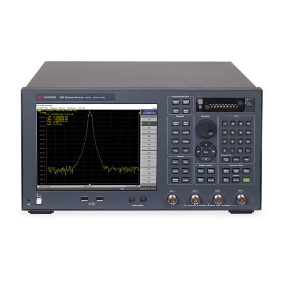
Quick Start Quick Start Quick Start helps you to understand the E5071C operation quickly. Overview Front Panel Rear Panel Screen Area Three Methods of Operation Basic Measurement Procedures Measurement Example of a Bandpass Filter... - Page 23 Used for choosing between power-on ( | ) and standby (O) state • of E5071C. To turn off the power for the E5071C, be sure to follow the steps described below: 1. First, press this standby switch or send a shutdown command from...
-
Page 24: Measurement
2. LCD Screen The E5071C is equipped with a 10.4-inch TFT color, touch-sensitive LCD screen for displaying traces, scales, settings, softkeys and other measurement related information. The touch screen LCD allows you to manipulate softkeys by touching the LCD screen directly with a finger. - Page 25 E5071C Selects the previous trace as the active trace. (Each time the key is pressed Trace causes the active trace to step down from the trace with the currently Prev designated number to one with a smaller trace number.) 4. RESPONSE Block A group of keys used mainly for setting up response measurements on the E5071C.
- Page 26 Trigger Menu enables you to specify the trigger mode and trigger source. You can specify the trigger mode for each channel. 6. Hard Disk Drive (Option 017 User only) The E5071C comes with a removable hard disk drive. For removal procedure, see Removing/Mounting Removable Hard Disk. 7. NAVIGATION Block...
- Page 27 (pressed) 8. ENTRY Block A group of keys used for entering numeric data is provided on the front panel of the E5071C. Key Name Description Type numeric characters or a decimal point at the position of the 0, 1, 2, 3 ..
- Page 28 While a dialog box is displayed, the focus is fixed on the dialog box and cannot be changed. 9. INSTR STATE Block A group of keys related to the macro function, store and call function, control/management function, and the presetting of the E5071C (returning it to the preset state). Key Name Description Displays the Macro Setup Menu on the right side of the screen.
- Page 29 E5071C Displays the Save/Recall Menu on the right side of the screen. Save/Recall Manipulating the Save/Recall Menu enables you to store the setup conditions to or read from the storage devices, calibration data, and trace data of the analyzer. First, temporarily saves the data for the image displayed on the...
- Page 30 E5071C. You can connect a banana-type plug to this terminal for grounding. 14. Probe Power The E5071C comes with two ports that can be used to provide power to external probes. See the Data sheet for the voltage and maximum current.
- Page 31 Connector type: 36-pin Ribbon (Centronics) connector 2. Ethernet Port A terminal for connecting the E5071C to a LAN (Local Area Network). Connecting this instrument to a LAN enables you to access the hard disk drive of this instrument from an external PC or to control this instrument by using SICL-LAN or telnet.
- Page 32 (on the power outlet side or device side of the cable) serves as the disconnecting device (device that cuts off power supply) of the E5071C. When the power supply must be cut off to avoid such danger as electric shock, pull out the power cable plug (on the power outlet side or device side of the cable).
- Page 33 A connector for outputting the internal frequency reference signal from the E5071C. By connecting this output connector to the external reference signal input connector of another device, the device can be phase-locked to the internal reference signal of the E5071C and used under this condition. Specification Value...
- Page 34 VBA programs inside the E5071C or to enter file names. Since the arrow keys and numeric keys on the keyboard work in the same way as the arrow keys and numeric keys on the front panel of the E5071C, you can use it instead of front panel operation.
- Page 35 E5071C Through this port, you can control the E5071C from external controllers. For more information on the measurement system using the USB port, see the USB Remote Control System. Specification Value Connector type Universal serial bus (USB) jack, type B (4 contact positions),...
- Page 36 Quick Start 22. Fuse for Bias Input Ports Fuse for Bias Input Ports is an optional component of E5071C. Valid for options: 235, 435, 285, 485. The fuse holder has been changed. The current fuse case has the black color. There is no functional differences.
- Page 37 E5071C Screen Area Screen Area: Names and Functions of Parts Channel Window Windows for displaying traces. Because a channel corresponds to a window, it is called a channel window. When the outer frame of a channel window is displayed in light gray, the channel is the active channel (the channel for which setup is being performed).
- Page 38 Quick Start 5-1. Channel Title Bar You can assign a title to each channel and have the title displayed on the bar. For more on setting up a channel title bar, see Labeling a window. 5-2. Trace Name/Measurement Parameter The names of the traces (Tr1 through Tr9)on the channel and their measurement parameters are displayed here.
- Page 39 E5071C 5-5. Trace Status Area The setup for each trace is displayed here. Trace status display Classification Contents Meaning inside [ ] Error correction Error correction: ON (OPEN (n) response (In the option TDR, calibration) this information should be ignored.)
- Page 40 Quick Start D- M (D- M&M) When a memory Execution of Data- Mem math trace is ON, see the contents inside () D*M (D*M&M) Execution of Data*Mem math D/M (D/M&M) Execution of Data/Mem math Electrical delay A numeric value other than 0 (zero) is specified as the electrical delay or phase offset.
- Page 41 E5071C (Receiver calibration) Scalar-mixer Error correction: ON correction (Scalar-mixer calibration) Equation Editor Equation Editor: ON 5-6. Reference Line Indicators The indicators that indicate the position of the reference line for the Y-axis scale in the rectangular display format. One indicator is to the right and the other is to the left of the scale ( and ).
- Page 42 Quick Start calibration coefficient for each channel. E5091A Property Displays the assignment information of the test ports on the channel. For details, see Displaying the multiport test set properties. Balanced Measurement Displays the topology for balanced measurement on the Topology Property channel.
- Page 43 E5071C Shows whether the fixture simulator is turned ON or OFF. Sim (displayed in blue) Fixture simulator: ON (not displayed) Fixture simulator: OFF 5-15. Averaging Status Displays the averaging factor and averaging count when averaging is turned on. n/m (displayed in blue) Averaging: ON (m: averaging factor;...
- Page 44 Quick Start 5-21. Marker Numbers The marker values are displayed in a list at positions 5-21, 5-22, and 5-23. Position 5-21 displays the marker numbers. For the active marker (the one for which setup and analysis are being performed), is displayed to the left >...
- Page 45 E5071C You can also move a marker to the desired position by placing the mouse pointer on the marker indicator or position of the marker itself (the pointer changes from ), moving the indicator vertically with the left mouse button pressed, and then releasing the button at the desired location.
- Page 46 Quick Start Data Entry Bar Used to enter numeric data into the E5071C. Press a hardkey or softkey to enter data, and the data entry bar will appear at the top of the screen. To assign a title to a channel window, an entry bar that allows you to enter letters and symbols by using the front panel keys or mouse is displayed instead.
- Page 47 E5071C 2-5. Enter Button After typing numeric values in the data entry area by using the keyboard or the numeric keys in the Block on the front panel, press this ENTRY button to finish the entry. Use the mouse to manipulate this button.
- Page 48 When updating of information displayed on the LCD screen is turned off, this indicator is displayed. 4-3. RF Output OFF Indicator When RF signal output is turned off, this indicator is displayed. 4-4. Measurement Status Displays the measurement status of the E5071C. Value Description Setup for measurement in progress Setup...
- Page 49 E5071C A measurement is in progress. Meas 4-5. VBA Status Displays the state of the execution of the VBA program in the E5071C. Value Description A VBA program is currently running. A VBA program has stopped. Stop 4-6. External Reference Signal Phase Lock...
- Page 50 An abnormal condition has been detected inside the E5071C. The unit (displayed in may be damaged. Notify the Customer Contact listed at the end of red) this manual or the distributor from whom the unit was purchased.
- Page 51 Block, Block, ACTIVE CH/TRACE RESPONSE STIMULUS Block, and Block on the front panel of the MKR/ANALYSIS INSTR STATE E5071C. The menus on the menu bar correspond to the key blocks, and their submenus to the hardkeys inside the key blocks.
- Page 52 Quick Start Softkey Menu Bar A group of keys on the screen called by the softkeys and menu bars. You can manipulate these keys by using the Block keys on the NAVIGATION front panel, the mouse, or the keyboard. You can perform manipulations by directly touching the screen with your finger instead of using a mouse.
- Page 53 E5071C To manipulate a menu bar, it has to be selected as the object to • manipulate (with the focus placed on it). When the focus is placed on a menu bar, the menu title area at the top is displayed in blue.
- Page 54 Quick Start 3-1. Softkey Menu Title The title of the softkey menu is displayed here. Double-clicking on this part of the menu bar displays the top layer of softkeys. 3-2. Scroll Arrow (Large) When the softkeys in a menu overflow the screen, using this key enables you to scroll the menu page by page.
- Page 55 E5071C You can scroll the softkey menu up or down by using the mouse to select and drag the scroll box (pressing the button on the object to be moved and then releasing the button at the desired location). The length and position of the scroll box indicate the length and position of the currently displayed part of the softkey menu relative to the entire menu.
- Page 56 Quick Start Three Methods of Operation You can operate the E5071C using one of three operating methods: using keys on the front panel, using a mouse and keyboard, and using the touch screen. This section illustrates these three operating methods through the example in which the channel window layout is set to the four-channel display as shown in the following figure.
- Page 57 E5071C 2. Press key to move the cursor to the Allocate Traces, then press or ( ) key. Enter 3. Press key to move the cursor to , then press key. Enter Operation Method Using a Mouse...
- Page 58 1. From the Response menu, press key. Display 2. Click Allocate Traces. 3. Click Operation Method Using the Touch Screen 1. Press key after presetting the E5071C (Executing key). Display Preset 2. Click/Press Allocate Traces. 3. Click/Press any desired setting.
- Page 59 E5071C Basic Measurement Procedures To better understanding how to use the E5071C, this section describes the basic measurement procedure using the E5071C and presents an example of the transmission measurement of a bandpass filter. Basic Measurement Flow 1. Determining measurement conditions Presetting the E5071C •...
- Page 60 947.5 MHz bandpass filter. To measure another device under test (DUT), change the measurement conditions to suit the particular DUT. STEP 1. Determining Measurement Conditions 1. Preset the E5071C. > OK Preset 2. Set the S-parameter to S21.
- Page 61 E5071C 7. Specify the IF bandwidth of the receiver as necessary. In this measurement example, the IF bandwidth is set to 10 kHz because of the need to lower the noise floor. > IF Bandwidth > > > STEP 2. Calibration To turn the error correction ON, set the calibration type to the full 2-port calibration and measure the calibration data.
- Page 62 Quick Start 4. In the same way as described above, measure the calibration data for the OPEN/SHORT/LOAD standards at the test port 2. 5. Connect the THRU standard (included in the calibration kit) between the measurement cables as shown in the figure below , and measure the thru calibration data.
- Page 63 (calculated based on the calibration data). > Save Type > State & Cal Save/Recall 8. Store the calibration file to the disk of the E5071C. The symbol "X" appearing in the operations below represent the assigned numbers to be used when the file is saved.
- Page 64 Quick Start 2. Set the appropriate scale by executing the auto scale. (See the below figure) > Auto Scale Scale You can also adjust the scale by entering arbitrary values in the Scale/Div button, Reference Position button, and Reference Value.
- Page 65 E5071C S21 trace after executing the auto scale STEP 4. Analyzing Measurement Results This section describes how to use the marker function to read out important parameters for the transmission measurement of the bandpassfilter (insertion loss, -3 dB bandwidth). Measuring the Insertion Loss 1.
- Page 66 Quick Start Measuring the -3 dB Bandwidth Using the marker bandwidth search function, the bandwidth, center frequency between two cutoff frequency points, Q value, and insertion loss are all read out. These parameters are described in the following table. If the two cutoff frequency points are not found, all data items •...
- Page 67 E5071C Frequency) frequency points Q (Q Value) Q = cent/BW loss (Insertion Loss) The measurement value of the active marker. 1. Display a marker. > Marker 1 Marker 2. Using one of the following methods, move the marker to the center frequency of the bandpass filter.
- Page 68 . Saving the Trace Data(in CSV format) You can save the trace data to the disk of the E5071C in CSV file format (extension: .csv). Since the CVS-formatted data to be saved is a text file, you can analyze the data using Microsoft Excel.
- Page 69 E5071C The image on the LCD display memorized in the volatile • memory (clipboard) (the image on the LCD display when the key is pressed) is saved. Capture/System...
- Page 70 Measurement Measurement This chapter provides information related to the measurements done through E5071C. Setting Measurement Conditions Calibration Making Measurements Data Analysis Data Output Optimizing Measurements Measurement Examples Fixture Simulator ...
- Page 71 E5071C Setting Measurement Conditions Setting Measurement Conditions Initializing Parameters Setting Channels and Traces Setting the System Z0 Setting Stimulus Conditions Selecting Measurement Parameters Selecting a Data Format Setting the Scales Setting Window Displays...
-
Page 72: Initializing Parameters
Measurement Initializing Parameters The E5071C has three different initial settings as shown below. Initial setting Restore method Preset state Press > the front panel or Execute the :SYST:PRES Preset command *RST state Execute the command *RST Factory default E5071C factory (default) settings setting The user can set items to be preset freely. - Page 73 • Other topics about Setting Measurement Conditions Overview The E5071C allows you to use up to 160 channels (when the number of traces is up to 9) to perform measurement under 160 different stimulus conditions. For each channel, up to 4, 6, 9, 12 or 16 traces (measurement parameters) can be displayed.
- Page 74 Measurement 1601 You may want to select the "1- channel, 4- trace" or "2- channel, 4- trace" configuration to save the time required to save/recall the instrument state file, since this takes longer with other configurations. More channels and traces requires longer measurement time.
- Page 75 E5071C From For these setup, A.08.10 press > System Service Menu > Channel/Trace Setup After the configuration setup is applied, memory swap From A.09.10 may occur during the measurement. The instrument may seem to pause during measurement. Its important to realize that the combination used to save a state file •...
- Page 76 Measurement setting of the window layout determines the number of channels displayed on screen. The execution of measurement for each channel does not • depend on how the channel is displayed (channels that are not displayed can be measured). For information on executing measurement for each channel (trigger mode and trigger source), refer to Making Measurements.
- Page 77 E5071C From Firmware revision A.08.10, channel display configuration of 8×9, 6×12 and 8×12 is added. Setting Trace Display Setting the number of traces Depending on the measurement parameters of the traces displayed for each channel, the sweep necessary for each channel is executed. For more information, refer to Sweep Order in Each Channel.
- Page 78 Measurement The procedure for setting the graph layout is as follows: 1. Press to select the channel for which Channel Next Channel Prev you want to set the graph layout. 2. Press > Allocate Traces. Display 3. Press the desired softkey to select the graph layout shown below. Graph Layout...
- Page 79 E5071C...
- Page 80 Measurement Active Channel active channel is the one whose settings can currently be changed. The window frame of the active channel is displayed brighter than the window frames of the other channels. To change the settings specific to a certain channel, you must first activate the channel. To change the active channel, use the following hardkeys: Hardkey Function...
- Page 81 E5071C > Sweep Sweep time/Sweep Sweep Setup delay time Time, Sweep Delay > Points Number of points Sweep Setup Segment sweep > Sweep Sweep Setup Type, Edit Segment Table, Segment Display Sweep mode > Sweep Sweep Setup Mode Trigger Settings >...
- Page 82 Measurement (ON/OFF) Smoothing > Smo Aperture/ Smoothing (ON/OFF) IF bandwidth > IF Bandwidth Calibration Marker Marker, Marker Search, Maker Fctn Analysis Fixture simulator > Fixture Analysis Simulator Time domain > Gating/ Analysis Transform Parameter conversion > Conversion Analysis Limit test >...
- Page 83 E5071C Setting the System Z The procedure for setting the system characteristic impedance (Z ) is as follows: 1. Press key. 2. Click Set Z , then input the system Z Other topics about Setting Measurement Conditions...
- Page 84 2. Press > Sweep Type. Sweep Setup 3. Press the desired softkey to select the sweep type. 4. To use the E5071C in CW Time sweep, refer to Setting CW Time Sweep Setting the Sweep Range...
- Page 85 E5071C There are two ways to set the sweep range: by specifying the lowest and the highest values and by specifying the center value and a span. Once the sweep range is set, it is possible to change the range by substituting the lowest value, the highest value, or the center value with a value (stimulus value) represented by a marker on the trace.
- Page 86 Measurement on the currently active trace. Start Sets the highest value to the stimulus value of the active marker Marker -> on the currently active trace. Stop Sets the center value to the stimulus value of the active marker Marker -> on the currently active trace.
- Page 87 E5071C...
- Page 88 Measurement Enable Stimulus Signal Output You can turn on/off the stimulus signal output, but this will prevent you from performing measurement. Therefore, you will not normally use this feature. This is mainly used to turn the output back to on after it has been turned off by the power trip feature.
- Page 89 3. Click Power > CW Freq, then enter the fixed frequency. Setting CW Time Sweep The E5071C supports sweep type of CW Time where the E5071C is set to a single frequency, and the data is displayed versus time. To use the E5071C in CW time, follow the procedure explained below: 1.
- Page 90 Setting Power Level with Auto Power Range (options 2D5, 4D5, 2K5 and 4K5 only) Auto Power range function works only with the E5071C options 2D5, • 4D5, 2K5 and 4K5 having a mechanical source attenuator. Auto power range functionality is neither required nor available in other E5071C options which are having electrical source attenuator.
- Page 91 E5071C 2. If you change the on/off setting of the level coupling, all ports are automatically changed to the same level value as that of port 1. 3. When setting level for all ports (Port Couple ON), click Power input the power level using the block keys on the front panel.
- Page 92 Measurement When Power Sweep is selected as sweep type, Step attenuation is selected with the start power condition and the maximum value of the Stop power (>= Start Power) is selected with the step ATT value. For example: Case of Start Power= -26 dBm •...
- Page 93 E5071C 1. Press to select the channel for which you Channel Prev/Channel Next want to set the correction coefficient. 2. Press key, then click Power > Slope [xxx dB/GHz] where Sweep Setup “xxx” represents the current set value and input the correction coefficient using the block keys on the front panel.
- Page 94 Measurement The following figure shows the definitions of the sweep time and the sweep delay time. Sweep delay is time before starting a sweep for each stimulus (source) port Setting Up the Sweep Time (Manual Sweep Time Mode) 1. Press keys to select the desired channel.
- Page 95 E5071C Selecting Measurement Parameters The E5071C allows users to evaluate the DUT (device under test) characteristics by using the following measurement parameters. S-parameters • Absolute • AUX Input • Other topics about Setting Measurement Conditions Operation Procedure 1. Press Prev) and...
- Page 96 This is useful in cases where the DUT (Device Under Test) works on a DC supply and it is required to measure the DC supply along with other measurements of the DUT using the E5071C. Example of AUX Input Measurement...
- Page 97 E5071C To use AUX Input Measurement: 1. Select Aux Input 1 or Aux Input 2 (depending upon the Aux port used for connection) by pressing the key. Meas 2. Select Range (1V or 10 V) [1 in the figure below].
- Page 98 Measurement Selecting a Data Format The E5071C allows you to display measured S-parameters by using the following data formats. The data format can be preset to factory settings using the Preset option. Rectangular display formats • Polar format • Smith chart format •...
- Page 99 E5071C Expanded Phase (can be displayed Degrees ( ° ) Measurement of deviation from phase format linear phase above +180 ° and below -180 ° ) Positive phase Phase (displayed in range Degrees ( ° ) Measurement of deviation from format from 0 °...
- Page 100 Measurement Real and imaginary parts • Smith chart format The Smith chart format is used to display impedances based on reflection measurement data of the DUT. In this format, traces are plotted at the same spots as in the polar format. The Smith chart format allows users to select one of the following five data groups for displaying the marker response values.
- Page 101 E5071C Use the following procedure to select a data format. 1. Press Prev) and Channel Next Channel Trace Next Trace Prev) to select the trace for which the data format will be set. 2. Press Format. 3. Press the softkey that corresponds to the desired data format.
- Page 102 Measurement Selects the Smith chart format (with log magnitude and Smith - Log / phase as the marker response values) Phase Selects the Smith chart format (with the real and Smith - Real / imaginary parts as the marker response values) Imag Selects the Smith chart format (with resistance and Smith - R + jX...
- Page 103 E5071C Setting the Scales Auto Scale • Manual scale adjustment on a rectangular display format • Other topics about Setting Measurement Conditions Auto scale The auto scale function is used to tailor each scale (scale/division and the reference line value) automatically in such a way that traces will appear at the proper size on the screen for easy observation.
- Page 104 Measurement Reference line Defines the value corresponding to the reference line. It must be value set using the unit on the Y-axis. The reference line value applies only to the active trace. (Reference Value) Manually setting scales on a rectangular display format 1.
- Page 105 E5071C It is also possible to turn off the display of graticule labels. For • details, refer to Turning_off_the_display_of_graticule_labels. Manual scale adjustment on the Smith chart/polar format Manual scale adjustment on the Smith chart format or the polar format is done by using the displacement (Scale/Div of the outermost circle).
- Page 106 Measurement 3. Click Marker -> Reference to change the reference line value to the marker response value. 4. If the reference marker is on and the stimulus value of the active marker is expressed using a value relative to the reference marker, the absolute stimulus value will be used to set the new reference line value.
- Page 107 E5071C Setting Window Displays Maximizing the specified window trace display • Turning off the display of graticule labels • Hiding Frequency Information • Labeling a Window • Setting Display Colors • Setting Display Magnification • Other topics about Setting Measurement Conditions...
- Page 108 Measurement 2. Press Display. 3. Click Graticule Label to turn graticule label display on or off. Hiding Frequency Information You can hide the frequency information from the screen in order to ensure its confidentiality or for other reasons. Hiding Frequency Information on the Screen Follow the steps below to hide frequency information on the measurement screen.
- Page 109 E5071C 1. Press keys to select the channel to be Channel Next/Channel Prev labeled. 2. Press key. Display 3. Click Edit Title Label,then the title label input dialog box appears. 3. Using the keys in the dialog box, type a label and click Enter.
- Page 110 Measurement Labels and lines of graphs • File display of the limit test and limit lines • Background • You set the color of each item by specifying the amounts of red (R), green (G), and blue (B) contained in the color. You can specify each level of R, G, and B in 6 steps (0 to 5).
- Page 111 E5071C Specifies the grid of graphs Graticule Sub Specifies the fail display in the limit test result Limit Fail Specifies the limit line Limit Line Specifies the background Background 4. Click Red (or, Green, or Blue). 5. Select the amount of the selected color from 0 to 5.
- Page 112 Measurement Calibration Calibration Overview Measurement Errors and their Characteristics Calibration Types and Characteristics Checking Calibration Status Clear Calibration Basic Calibration Selecting Calibration Kit OPEN/SHORT Response Calibration (reflection test) THRU Response Calibration (transmission test) Enhanced Response Calibration ...
- Page 113 E5071C Modifying Calibration Kit Definition Specifying Different Standard for Each Frequency Receiver Calibration Power Calibration Partial Overwrite Simplified Calibration Adapter Removal-Insertion Unknown Thru Calibration Performing 8 term Calibration using External PC ...
- Page 114 Measurement Measurement Errors and their Characteristics Overview • Drift Errors • Random Errors • Systematic Errors • Other topics about Calibration Overview It is important to understand the factors contributing to measurement errors in order to determine the appropriate measures that should be taken to improve accuracy.
- Page 115 E5071C (You don't need to worry about these errors since the E5071C does not have mechanical RF switches). Connector repeatability errors Connector repeatability errors are caused by fluctuations in the electrical characteristics of connectors due to wear. These errors may be reduced by handling connectors with care.
- Page 116 The number of directivity errors of the E5071C is the number of stimulus ports you use.
- Page 117 When a certain port is a stimulus port, a load match error is defined for each of the other ports. Therefore, the number of load match errors for the E5071C is the total number of combinations of stimulus ports and response ports.
- Page 118 The number of reflection tracking errors for the E5071C is simply the number of stimulus ports you use.
- Page 119 E5071C Calibration Types and Characteristics The table shows the different types of calibrations and the features of each method. Calibra tion Standard (s) Measurement Characteristic Corrected Error Factor Used Parameters Metho • Low accuracy calibra None None All parameters •...
- Page 120 Measurement chance of operator error • • OPEN Highly accurate 1- • SHORT port • measurement LOAD • Highly accurate 2- port measurement (higher than Following 5 error terms: response Ecal module calibration) (2-port) • Directivity (Ed1) Enhan • Quick •...
- Page 121 E5071C (Es1,Es2,Es3) • Load Match (El21,El31,El12,El32,El • OPEN • 13,El23) Highly • SHORT accurate 3- • Transmission Tracking port • LOAD (Et21,Et31,Et12,Et32,Et measurement 13,Et23) • THRU • Reflection Tracking (Er1,Er2,Er3) • High- accuracy 3- S11, S21, S31, S12, • OPEN...
- Page 122 Measurement tion SHORT) • ports) measurement Source Match (Es1,Es2) • • THRU • Effective for Load Match (El1,El2) non-coaxial • LINE • Transmission Tracking device (Et21,Et12) • measurement MATCH • Reflection Tracking (Er1,Er2) Following 27 error terms: • Directivity (Ed1,Ed2,Ed3) •...
- Page 123 E5071C • Reflection Tracking (Er1,Er2,Er3,Er4) • High- accuracy 4- port S11, S21, S31, [S41], measurement • Reflection S12, S22, [S32], Effective for Simplif (open or [S42], S13, [S23], non-coaxial ied 4- short) S33, S43, [S14], device port Same as 4-port TRL [S24], S34, S44 •...
- Page 124 Measurement Checking Calibration Status Execution Status of Error Correction for Each Channel • Execution Status of Error Correction for Each Trace • Acquisition Status of Calibration Coefficient for Each Channel • Other topics about Calibration Execution Status of Error Correction for Each Channel You can check the execution status of error correction for each channel with the error correction status.
- Page 125 E5071C You can check the status of the error correction actually executed for each trace with the trace status area. For a trace for which error correction is executed, the applied calibration type is indicated in the trace status area by the symbols in the table below.
- Page 126 Measurement The simplified full 3/4-port calibration and the simplified 3/4- • port TRL calibration are not discriminated from the normal full- port and TRL calibrations, and F is displayed. Procedure to turn on/off calibration property display Follow these steps to turn on/off the calibration property display. 1.
- Page 127 Clear Calibration This softkey clears the user calibration data. When Calibration is done for a particular DUT, the data get stored in the E5071C. To clear this data, Clear Calibration can be used which removes the User calibration data from the E5071C.
- Page 128 Measurement Basic Calibrations Selecting Calibration Kit Overview • Procedure • Other topics about Basic Calibration Overview Before executing calibration, you need to select a calibration kit. If you use a calibration kit other than a predefined one, you need to define it.
- Page 129 E5071C OPEN/SHORT Response Calibration (reflection test) Overview • Procedure • Other topics about Basic Calibration Overview In OPEN or SHORT response calibration, calibration data are measured by connecting an OPEN or SHORT standard, respectively, to the desired test port. For frequency response, these calibrations effectively eliminate the reflection tracking error from the test setup reflection test using that port.
- Page 130 Measurement 2. Press key. 3. Click Calibrate. 4. Select OPEN or SHORT response calibration. Softkey Function Displays softkeys for performing an OPEN response Response calibration (response calibration with an OPEN (Open) standard) Displays softkeys for performing a SHORT response Response calibration (response calibration with a SHORT (Short) standard)
- Page 131 E5071C...
- Page 132 Measurement THRU Response Calibration (transmission test) Overview • Procedure • Other topics about Basic Calibration Overview In THRU response calibration, calibration data are measured by connecting a THRU standard to the desired test port. This calibration effectively eliminates the frequency response transmission tracking error from the test setup in a transmission test using that port.
- Page 133 E5071C 4. Select the test ports (and corresponding S parameters) upon which a THRU response calibration is to be performed. 5. Make a between the selected test ports (between the connectors to which the DUT will be connected). 6. Click Thru to start the calibration measurement.
- Page 134 Measurement b. Click Isolation (Optional) to start the calibration measurement. 7. Click Done to terminate the response calibration (and the LOAD isolation calibration) process. Upon pressing this key, calibration coefficients will be calculated and saved. The error correction function will also be automatically enabled.
- Page 135 E5071C Enhanced Response Calibration Overview • Procedure • Other topics about Basic Calibration Overview In enhanced response calibration, calibration data are measured by connecting an OPEN standard, a SHORT standard, or a LOAD standard to the output port (or a THRU standard between two ports).This calibration...
- Page 136 Measurement 1. Press keys to select the channel for which Channel Next/Channel Prev you want to perform the calibration. 2. Press key. 3. Click Calibrate. 4. Click Enhanced Response. 5. Click Ports to select the test ports on which an enhanced response calibration will be performed.
- Page 137 E5071C b. Click Isolation (Optional) to start the calibration measurement. c. Click Return. 14. Click Done to terminate the enhanced response calibration process. Upon pressing the key, calibration coefficients will be calculated and saved. The error correction function will also be...
- Page 138 Measurement 1-Port Calibration (reflection test) Overview • Procedure • Other topics about Basic Calibration Overview In 1-port calibration, calibration data are measured by connecting an OPEN standard, a SHORT standard, and a LOAD standard to the desired test port. This calibration effectively eliminates the frequency response reflection tracking error, directivity error, and source match error from the test setup in a reflection test using that port.
- Page 139 E5071C 7. Connect a SHORT calibration standard to the selected test port (connector to which the DUT is to be connected). 8. Click Short to start the calibration measurement. 9. Connect a LOAD calibration standard to the selected test port (connector to which the DUT is to be connected).
- Page 140 Measurement Full 2-Port Calibration Overview • Procedure • Other topics about Basic Calibration Overview In full 2-port calibration, calibration data are measured by connecting an OPEN standard, a SHORT standard, or a LOAD standard to two desired test ports (or a THRU standard between two ports).This calibration effectively eliminates the directivity error, crosstalk, source match error, frequency response reflection tracking error, and frequency response transmission tracking error from the test setup in a transmission or reflection test using...
- Page 141 E5071C 3. Click Calibrate > 2-Port Cal. 4. Click Select Ports, then select the test ports on which you will perform full 2-port calibration. (In the procedure below, the selected test ports are denoted as x and y.) 5. Click Reflection.
- Page 142 Measurement Click Port x-y Isol to start the calibration measurement (x and denote the port numbers to which the LOAD standard is connected). Click Return. Click Done to terminate the full 2-port calibration process. Upon pressing this key, calibration coefficients will be calculated and saved.
- Page 143 E5071C Full 3-Port Calibration Overview • Procedure • Other topics about Basic Calibration Overview In full 3-port calibration, calibration data are measured by connecting an OPEN standard, a SHORT standard, or a LOAD standard to three desired test ports (or a THRU standard between three ports). This calibration...
- Page 144 Measurement Procedure 1. Press keys to select the channel for which Channel Next/Channel Prev you want to perform the calibration. 2. Press key. 3. Click Calibrate > 3-Port Cal. 4. Click Select Ports, then select the test ports on which you will perform full 3-port calibration.
- Page 145 E5071C 5. Click Return. 6. If an isolation calibration must be performed using a LOAD standard, follow the procedure below. 7. Click Isolation (Optional). 8. Connect a LOAD standard to each of the three test ports (connectors to which the DUT is to be connected).
- Page 146 Measurement Full 4-Port Calibration Overview • Procedure • Other topics about Basic Calibration Overview In full 4-port calibration, calibration data are measured by connecting an OPEN standard, a SHORT standard, or a LOAD standard to the four test ports (or a THRU standard between the four ports). This calibration effectively eliminates the directivity error, crosstalk, source match error, load match error, frequency response reflection tracking error, and frequency response transmission tracking error from the test setup in a...
- Page 147 E5071C 1. Press keys to select the channel for which Channel Next/Channel Prev you want to perform the calibration. 2. Press key. 3. Click Calibrate > 4-Port Cal. Reflection 1. Click Reflection. 2. Connect an OPEN calibration standard to test port 1.
- Page 148 Measurement Connect a LOAD standard to each of the four test ports (connectors to which the DUT is to be connected). Click Port 1-2 Isol to start the calibration measurement. Perform the each calibrations by clicking Port 1-3 Isol, Port 1-4 Isol, Port 2-3 Isol and Port 2-4 Isol.
- Page 149 ECal, the calibration data for the minimum frequency or maximum frequency are used for the exceeding frequency range and extrapolation is being executed. When using Ecal with the E5071C options 2D5, 4D5, 2K5 and • 4K5 , wait time is inserted automatically for stable calibration results.
- Page 150 When the ECal is connected with USB ports at the first time, ECal driver installation is required. 1. Connect a Ecal to the USB port of the E5071C. 2. Select No, not this time, then click Next. 3. Select Install the software automatically (Recommended), then click...
- Page 151 E5071C 4. Click Finish.
- Page 152 > ECal > ECal. If a single ECal is connected, only one ECal is listed here. When multiple ECal are connected E5071C, all the connected ECals are listed here. The first line indicates the model number of the ECal and the second line...
- Page 153 E5071C E5071C revision A.9.60 and above allows multiple ECal to be connected at any one time. To perform calibration using your preferred ECal module, select the desired ECal from the list and perform 1-Port, 2-Port, 3-Port or 4-Port calibration just as its performed in single ECal.
- Page 154 ECal module. 1. Connect the USB port on the ECal module with the USB port on the E5071C via a USB cable. This connection may be made while the E5071C's power is on. 2. Allows the ECal module to warm up for 15 minutes until the module indicates from WAIT to READY.
- Page 155 E5071C Other topics about Calibration with ECal...
- Page 156 Procedure 1. Connect the USB cable between the USB port of the 4-port ECal module and the USB port of the E5071C. You can make this connection while the E5071C's power is on. 2. Allows the ECal module to warm up for 20 minutes until the module indicates from WAIT to READY.
- Page 157 Select a port and start calibration. If you do not have to select a port, this step is skipped. The E5071C detects the test ports connected to the ECal and then measurement starts. If the selected test ports to be calibrated is not connected to the ECal module, an error occurs.
- Page 158 5. Press key. 6. Click ECal. 7. Click 2 Port ECal. When using a 2-port E5071C, pressing this key performs a 2-port ECal. When using a 3-port or 4-port E5071C, click one of the softkeys to start a full 2-port calibration.
- Page 159 E5071C You can connect the ports of the ECal and the test ports of the • E5071C arbitrarily. Connected ports can be manually specified although they are automatically detected before data measurement. For more information, Turning off ECal auto- detect function...
- Page 160 • Other topics about Calibration with ECal Overview A VBA macro (ECal Assistant) is pre-installed in the E5071C to carry out a full 3-port or a full 4-port calibration using the 2-port ECal. ECal Assistant does not perform isolation calibration.
- Page 161 4-Port (for a full 4-port calibration) radio button. When a full 3-port calibration is carried out on an E5071C, select the test ports to be calibrated from the drop-down list box below the 3-Port button (either 1-2-3, 1-2-4, 1-3-4, or 2-3-4).
- Page 162 Measurement Upon completion of measurement, the following dialog box appears. Click the Next button. The following dialog box appears. Re-connect the ECal module following the instructions given in each dialog box and continue the calibration process. When all calibration data have been collected, a dialog box with the Complete! sign appears as shown in the following figure, click Done to finish the calibration.
- Page 163 E5071C...
- Page 164 Unknown Thru Calibration E5071C allows you to perform Thru calibration of ECal as the unknown Thru calibration. In this function, the Thru calibration is performed with the Thru standard in ECal, however, the stored Thru calibration data in ECal is not used.
- Page 165 The E5071C can set ECal to the state used to verify the measurement parameters and then copy the appropriate characteristics of that verification state to the memory trace from the ECal's built-in memory.
- Page 166 Measurement When using an adapter to the ECal, click Characterization and then press the softkey corresponding to the characterization for the adapter you are using. Click Confidence Check. Compare the data trace and the memory trace and verify whether measurement is correct. The following is the procedure for comparison when simultaneously displaying the data trace and the memory trace.
- Page 167 E5071C...
- Page 168 3. Click ECal > Orientation, and select Manual. 4. Specify a test port of the E5071C. 5. Specify an Ecal port for the port of the E5071C you specified. Even if the connection is wrong with the auto-detect function •...
- Page 169 • Other topics about Calibration with ECal Overview The E5071C allows you to execute ECal calibration with user-defined characteristics instead of the ECal characteristics defined as the factory default. This feature is called User-characterized ECal, and it is used to execute ECal calibration when an adapter is connected to the ECal module.
- Page 170 1. Connecting ECal Module Connect the USB cable between the USB port of the ECal module and that of the E5071C. You can make this connection while the E5071C's power is 2. Setting Stimulus Condition Set the stimulus condition of the channel for which you want to measure the user characteristics.
- Page 171 1601 with 1 channel and 4 traces. Click OK. e. The ECal part (1 in the figure below) displays the information of the ECal module connected to the E5071C. f. Click Refresh (2 in the figure below) to update the information if you have connected another ECal module after the macro has been started.
- Page 172 Click Measure (4 in the figure) to start measurement. a. You can select any port of the ECal module and any test port of the E5071C for connection; the E5071C automatically recognizes the connected ports before measurement. 6. Storing the User Characteristics to the Memory a.
- Page 173 E5071C parts Characterization, Connectors, and Adapter Description are left blank; if already used, the stored contents are displayed. Characterization Enter the information (operator, used analyzer, and so on) when measuring user characteristics as necessary. Connectors Select the connector types of the adapters for the ECal module's test ports.
- Page 174 Measurement f. The following dialog box is displayed to confirm execution. Click OK to start storing the user characteristics. a. Do not disconnect the USB cable or terminate the VBA macro by force while the VBA macro is storing data to the ECal's built-in flash memory.
- Page 175 1. Connect the USB cable between the USB port of the ECal module and that of the E5071C. You can make this connection while the E5071C's power is ON. 2. Start the VBA macro according to Starting the VBA MACRO 3.
- Page 176 Measurement The execution procedure for the User-characterized ECal is the same as for normal ECal except that it requires the user characteristics to be selected in advance. 1. Press keys to select the channel for which Channel Next/Channel Prev you want to execute calibration. 2.
- Page 177 E5071C The information you entered in Connectors ( 3 of User Characterization Info screen)
- Page 178 Measurement Advanced Calibrations Setting the trigger source for calibration Overview of Trigger Source • Setting Trigger Source • Other topics about Advanced Calibration Overview of Trigger Source You can set the trigger source for calibration before executing calibration. You can select it from "Internal" or "System." Setting it to "System" allows you to use the same trigger source setting for calibration and measurement.
- Page 179 E5071C Selects "System." System...
- Page 180 Measurement Sliding and Offset Load Calibration Supported Calibration • Sliding Load Calibration • Offset Load Calibration • Other topics about Advanced Calibration Supported Calibration The following table shows the supported calibration for the sliding load and offset load. Enhan Adapt Scal Calibra Respo...
- Page 181 E5071C Follow these steps to perform calibration using sliding load. The example demonstrates re-calibration for full 1-port calibration. 1. Press keys to select the channel for which Channel Next/Channel Prev you want to perform the calibration. 2. Press key. 3. Click Calibrate > Cal Kit.
- Page 182 Measurement shorter offset element can be a zero-length (Flush-thru) offset. The load element is defined as a 1-port reflection standard. An offset load standard is used when the response of the offset elements are more precisely known than the response of the load element. This is the case with waveguide. Measurement of an offset load standard consists of two measurements, one with each of the two offset elements terminated by the load element.
- Page 183 E5071C Click Offset Line 1 Thru. Make a LOAD connection on the selected test port with a offset load (X-band Delay line). Click X-band Delay Line. Click Done. Click Return twice. Now, all Short, Open and Load should have check mark on their left.
- Page 184 The terms used in this section are defined as follows: Standard An accurate physical device, for which the model is clearly defined, used to determine system errors. With the E5071C, the user may define up to 21 standards per calibration kit. Each standard is numbered from 1 through...
- Page 185 E5071C 21. For example, standard 1 for the 85033E 3.5-mm calibration kit is a SHORT standard. Standard type The type of standard used to classify a standard model based on its form and construction. Six standard types are available: SHORT, OPEN, LOAD, delay/THRU, Unknown Through, and arbitrary impedance.
- Page 186 Measurement Transmission Standard Model (THRU)
- Page 187 E5071C Offset Z0 The offset impedance between the standard to be defined and the actual measurement plane. Normally, this is set to the system's characteristic impedance. Offset Delay The delay that occurs depending on the length of the transmission line between the standard to be defined and the actual measurement plane.
- Page 188 Measurement C2 unit: (Farads/Hz C3 unit: (Farads/Hz L0, L1, L2, L3 It is extremely rare for a SHORT standard to have perfect reflection characteristics at high frequencies. This is because the residual inductance of the standard causes a phase shift that varies along with the frequency. It is not possible to eliminate this effect.
- Page 189 E5071C 3. Click Modify Kit. To change the pre-defined connector type (e.g. OPEN(f) to OPEN (m)) skip to the specifty classes. 4. Click Define STDs. 5. Select the standard to be redefined from among standards numbered 1 through 21. 6. Click No Name > Label and input a new label for the standard using the keypad displayed on the screen.
- Page 190 Measurement Sets C1 Sets C2 Sets C3 Sets L0 Sets L1 Sets L2 Sets L3 Sets the offset delay Offset Delay Sets the offset Z0. Specify 1 ohm when Offset Z0 Waveguide is set for the media type. Sets the offset loss Offset Loss Arb.
- Page 191 E5071C 8. Repeat step 1 to step 5 to redefine all standards for which changes are necessary, then click Return. Procedure to define standard class 1. Press key. 2. Click Modify Kit. 3. Click Specify CLSs, then select the class.
- Page 192 Measurement Selects port 2 and port 4. Port 2-4 Selects port 3 and port 4. Port 3-4 7. Select the test port. Select Set All to use the same standards for all test ports. 8. Select the standards to be registered in the class from among standards numbered 1 through 21.
- Page 193 E5071C 3. Select STD Type > Delay/Thru. 4. Set Offset Loss to 1.3Gohm/s, and Offset Delay to 0. 5. Click Return to return to the Define STD menu. 6. In the same way, repeat the procedure to enter the definition of REFLECT to No.
- Page 194 Measurement Procedure to register Line 1/2 to subclass 2/3 1. Click Sub Class2. 2. Click TRL Line/Match > Set All > LINE <7G > Return. 3. Click Sub Class3. 4. Click TRL Line/Match > Set All > LINE >7G > Return. 5.
- Page 195 E5071C test port impedance differ. 5. Click Reference Plane to select the measurement data of the standard used for calculating the reference plane. Softkey Function Uses the length of the thru/line standard to calculate the Thru calibration plane. Uses the reflection coefficient of the reflection standard Reflect to calculate the calibration plane.
- Page 196 3. Select > Modify Cal Kit > Specify CLSs > Sub Class. The subclass gender is set from the E5071C side and not from the Calibration kit side. If both male/female are set using subclass in advance, the gender which is used for the calibration can also be changed programmatically using SCPI.SENSe(Ch).CORRection.COLLect.ACQuire.SUBClass...
- Page 197 E5071C 3. Click Modify Cal Kit > Import Cal Kit... to open the dialog box. 4. Specify a folder, enter a file name, and click Open. Restoring Definition File of Calibration Kit 1. Press key. 2. Click Cal Kit, then select a calibration kit.
- Page 198 Measurement Specifying Different Standards for Each Frequency Overview • Defining Standards for Each Subclass • Disabling Standards Defined for a Subclass • Possible Cases of Frequency Ranges Using Subclasses • Other topics about Advanced Calibration Overview This section demonstrates the procedure to define a different open standard for each frequency band, based on the following information: Standard Label name...
- Page 199 E5071C This section demonstrates the procedure to specify a different OPEN standard for each frequency band, using subclasses #1 and #2. In this example, the standards created in Defining different standard for each frequency band are used. 1. Press Key.
- Page 200 Measurement Possible cases of frequency ranges Execution of calibration Example 1, When frequency ranges specified with Possible subclasses overlap Example 2, When frequency ranges specified with Impossible subclasses do not cover a part of a measurement frequency range Example 3, When a frequency range specified with Possible a subclass lies outside the measurement frequency range...
- Page 201 E5071C Example 3, When a frequency range specified with a subclass lies outside the measurement frequency range For a measurement frequency range (1 GHz to 5 GHz), if you define a standard of subclass 1 (1 GHz to 5 GHz) and a standard of subclass 2 (5 GHz to 8 GHz), calibration possible for subclass 2 although it is out of the measurement frequency range.
- Page 202 Measurement...
- Page 203 • Other topics about Advanced Calibration Overview The E5071C has a function to calibrate the gain of the individual receivers in absolute value measurement. The receiver calibration function calibrates the gain of the receiver by inputting the output power of a stimulus port that has been assigned a correct value by the power calibration to the port of the receiver you need to calibrate.
- Page 204 Measurement blue) receiver ports. Extrapolated calibration data is used. (displayed in Error correction is performed for some of the grey) receiver ports. Extrapolated calibration data is used. (displayed in Error correction is not performed. gray) (At least one receiver port is turned on for error correction, but valid calibration data are not available.) None...
- Page 205 E5071C 5. Click the softkey corresponding to the port you want to calibrate. Measuring Calibration Data The power calibration information on both the receiver port and • source port is used to calculate calibration coefficients. The accuracy of receiver calibration will increase if power calibration is implemented for both the receiver port and the source port before starting receiver calibration.
- Page 206 • calibration would be -20 dBm. The value of offset is independent for each channel. 8. The E5071C provides an option to calibrate both the Receiver and Transmitter end, or only the Receiver end, or only the Transmitter end: Click Receiver Calibration > Calibrate Both to start •...
- Page 207 E5071C Click Receiver Calibration > Calibrate R to calibrate the • receiver end only. When Calibrate R is selected, the Select Port setting is used and • the Source Port setting is ignored. Click Receiver Calibration > Calibrate T to calibrate the •...
- Page 208 • Other topics about Advanced Calibration Overview The E5071C has a calibration feature for power level output that uses the power meter (power calibration). The power calibration function outputs a stimulus signal with a more accurate power level (closer to the set value) by measuring calibration data (power level) in advance with the power meter and sensor.
- Page 209 E5071C gray) ports; interpolated calibration data is used. If you turn on the error correction function when the stimulus setting is different from that when the power calibration data were acquired, power level error correction is performed with interpolated calibration data only when calibration data can be interpolated (extrapolation is not performed for calibration data).
- Page 210 GPIB or USB (for USB enabled Power Meters) from the E5071C. To control the power meter through GPIB from the E5071C, connect the USB port of the E5071C and the GPIB/USB connector of the power meter through the USB/GPIB interface and set the GPIB address of the connected power meter with the E5071C.
- Page 211 E5071C, this setting would be ignored. If you use the E4418A, E4419A, EPM-441A, or EPM-442A with • Firmware revision Ax.02.00 or earlier and you set the calibration factor table with the E5071C, calibration is executed by both the...
- Page 212 Measurement power meter and the E5071C due to this Firmware revision, and thus you cannot obtain correct measurement results. Therefore, never set the calibration factor table under this condition with the E5071C. Use the following procedure to set the power sensor's calibration factor table: 1.
- Page 213 E5071C 4. Click Export to CSV File to open the Save As dialog box. At this time, CSV File (extension *.csv) is selected as the file type. 5. Enter a file name in the File Name box and press the Save button to save the power sensor calibration factor table.
- Page 214 Measurement 2. Click Power Calibration > Sensor A/B Settings > Zero Type > INT|EXT to select from internal or external zeroing. 3. Click Power Calibration > Sensor A/B Settings > Zero/Calibrate Sensor 4. For U2000 Series USB power sensors, Sensor B setting is disabled.
- Page 215 E5071C 4. Click Loss Compen > Compensation. Each press toggles the selection between ON/OFF. Creating loss compensation table Follow the steps below to set the loss compensation table. 1. Press key. 2. Click Power Calibration. 3. Select a port (refer to Selecting target port of error correction).
- Page 216 Setting a tolerance for power calibration The E5071C provides an option to set the tolerance value for power calibration. This function is to save time for the power calibration by aborting the calibration process once the measurement value goes outside the specified tolerance and is NOT to settle the power level within the specified tolerance.
- Page 217 When using the power sensor calibration factor table of the E5071C, set the calibration factor to 100% and execute the calibration of the power sensor.
- Page 218 When the calibration coefficients become inappropriate over • time or the status on the E5071C side from the calibration surface changes due to replacement of a cable or connector, you need to also perform thru measurement when partial overwrite is required for reflection or isolation measurement.
- Page 219 E5071C 5. Click Transmission. 6. Make a thru connection between selected test ports x and y (between the connectors to which the DUT is connected). 7. Click Port x-y Thru (x and y are the thru-connected port numbers) to start the re-measurement of the calibration standard.
- Page 220 Measurement Simplified Calibration Overview • Simplified Full 3/4-port Calibration • Simplified 3/4-port TRL Calibration • Other topics about Advanced Calibration Overview The simplified calibration calculates the calibration coefficients by skipping part of thru measurement (and line measurement for TRL measurement) that is necessary for the full 3/4-port calibration and the 3/4-port TRL calibration.
- Page 221 E5071C The types of thru measurement you can omit are determined by the ports you select. Some types of thru measurement cannot be omitted. The table below shows the types of thru measurement that can be omitted. Omissible Thru Type at Full 3-port Calibration...
- Page 222 Measurement The types of thru/line measurement and line/match measurement you can omit are determined by the ports you select. Some types of measurement cannot be omitted. You cannot omit thru/line measurement only or line/match measurement only, even for an omissible measurement path. Omissible Thru type at 3-port TRL calibration Ports used Omissible measurement...
- Page 223 E5071C (Recommended) is displayed. The display after the execution of the omissible line/match measurement is 2-3 Line/Match, and the display for the remaining omissible line/match measurement is 2-3 (Optional). The softkeys (Fwd and Rvs) for forward measurement and reverse measurement for the omissible line/match measurement do not change.
- Page 224 Other topics about Advanced Calibration About Adapter Removal Adapter Removal is a technique used to remove any adapter characteristics from the calibration plane. The E5071C uses the following adapter removal process to remove adapter characteristics: 1. Perform calibration with the adapter in use.
- Page 225 This above described method also makes it possible to add adapter characteristics to a port with n-port full calibration. This allows you to make a measurement with the adapter. E5071C uses the following adapter insertion process to insert adapter characteristics: 1.
- Page 226 Some calibration kits such as the waveguide calibration kit have • operational frequency range defined by Minimum and Maximum frequency. When the E5071C stimulus setting is out of the operational frequency range, you cannot click Done key or finish the calibration by remote control. In this case, use a...
- Page 227 E5071C 1. Using Adapter Insertion: a. Perform a SOLT F2P Calibration at Port 1 (3.5mm) using Z0=50 ohm b. Perform Adapter insertion at Port 2 (Z0=1) using P11644A...
- Page 228 Measurement 3. Using Adaptor Removal: a. Perform a SOLT/TRL F2P Calibration at P band WG (Z0 = 1) b. Perform Adapter removal at port 1 (Z0=50) using 85052D 4. Using Port Extension: a. Perform a SOLT F2P calibration at Port 1 (3.5mm) with Z0 = b.
- Page 229 E5071C Procedure for Adapter Removal/Insertion The S parameter of a reciprocal adapter can be determined when the following data is available: 1. Open, Short, and Load measurements. 2. Actual values derived from the CalKit definitions. 3. An approximate length of the adapter.
- Page 230 Measurement calibration plane (adapter insertion) to connect your DUT, perform the calibration without an adapter. 2. Open the Adapter Removal menu: > Calibrate > Adapter Removal 3. Select the Port in/from which you want to insert/remove Adapter characteristics from Select Port (e.g. 1) (1 in the above figure). A * sign appears in front of the port is a valid port to conduct adapter removal/insertion as the full n-port calibration has been performed on the port.
- Page 231 In this case, use a calibration kit that has proper frequency range, or change the E5071C stimulus setting to proper range that the calibration kit can cover. Refer to the calibration kit manual or definition in the...
- Page 232 Adapter to move the phase of adapter (which is removed or inserted) to 180 degrees. Difference between Traditional Network Analyzer & E5071C Adapter Calibration Usually, two-port network analyzers removes adapter characteristics by performing two sets of Full 2 Port Calibration as shown below:...
- Page 233 However, this method is not suitable for a multi-port network analyzer because it will require as many sets of Full 2 Port Calibration as twice the number of port combinations. Therefore, the E5071C uses an advanced method to remove Adapter characteristics described in About Adapter...
- Page 234 Measurement Unknown Thru Calibration Overview • Procedure • Other topics about Advanced Calibration Overview Unknown Thru Cal is the preferred THRU method of calibrating the ENA to measure a non-insertable device. The major benefits of using a unknown Thru calibration are: It is easy to perform.
- Page 235 E5071C The electrical delay is automatically measured and can be confirmed. Press > Port Extensions > Extension Port 1 {Value} 4. If there is an offset in the short circuit used to terminate the Unknown Thru standard, remember to subtract its electrical length from the measurement result.
- Page 236 Procedure Turning off the "System Calibration" In its default setting, the E5071C applies "system calibration" to the measured S-parameter data. Because the "system calibration" is applied only to the S-parameter measurement data and NOT to the absolute value measurement data, it interferes with 8-term error model calibration when calculating error coefficients on external computer.
- Page 237 Set the "RF ranging mode" to MANual (3 GHz, 4.5 GHz, 6.5 GHz and 8.5 GHz option only) There is a hardware function called "RF ranging mode" on E5071C. The default setting of this state is AUTO, and this state interferes with 8-term error model calibration when calculating error coefficients on external computer.
- Page 238 Since the "RF ranging" is hold during the measurement, the • system dynamic range of the E5071C will degrade by 6dB, as a result of the 8-term calibration performed externally. However, there is NO dynamic range degrade by 8-term error model calibration with internal calibration of the ENA.
- Page 239 • Other topics about Mixer Calibration Overview The E5071C has a scalar-mixer calibration function for measuring frequency conversion devices. Scalar-mixer calibration allows you to measure the magnitude value and reflection parameter of the mixer's conversion loss with very high accuracy by performing calibration using calibration standards (OPEN/SHORT/LOAD) in combination as well as a power meter.
- Page 240 Measurement be divided into two types of errors: one associated with the stimulus side at the input frequencies and the other associated with the response side at the output frequencies. As previously discussed, calculating the transmission tracking (ETF) based on both stimulus and response sides is the key to using error correction during frequency-offset measurements.
- Page 241 E5071C You can confirm the progress of error correction for each channel by viewing the error calibration status. For the traces in which the scalar- mixer is valid, the status [S2] is added. In scalar-mixer calibration, the normal calibration coefficient is •...
- Page 242 Measurement 6. For the scalar-mixer calibration, only one direction with 2-ports calibration is available. "One direction" means the forward or reverse direction. Two directions may be used among the same ports, but this would not be full 2-port scalar-mixer calibration but simply the simultaneous operation of single-direction scalar- mixer calibrations..
- Page 243 E5071C Click Port x@Freq x Short to start measurement of the calibration standard. Click Port x@Freq y Short to start measurement of the calibration standard. Disconnect the SHORT calibration standard, then connect LOAD calibration standard in its place. Click Port x@Freq x Load to start measurement of the calibration standard.
- Page 244 Measurement Click Done to exit the scalar-mixer calibration. This step allows the calibration coefficient to be calculated, turning on the error correction function automatically. Procedure Using ECal Kit 1. Before starting scalar-mixer calibration, verify that the frequency- offset is activated by clicking key >...
- Page 245 Click ECal & Done. The calibration coefficient will be calculated, turning on the error correction function automatically. If the ECal module is not connected to the E5071C or power • calibration have not been done yet, the ECal & Done menu item will not be not available.
- Page 246 • Other topics about Mixer Calibration Overview of Vector-Mixer Calibration The E5071C has a vector-mixer calibration function for use in measuring frequency conversion devices. The vector-mixer calibration allows you to measure the magnitude, phase and group delay of the mixer's conversion loss by using in combination...
- Page 247 E5071C Since the up/down conversion method is used in vector-mixer • calibration, the frequency-offset function is not used. But, option 008 is required to use the VMC macro, SG control, and etc. Overview of Vector-Mixer Calibration The vector-mixer calibration requires the characteristics data for the calibration mixer with IF filter.
- Page 248 Measurement characteristics of the calibration mixer from the measurement result. You can use the IF filter to select any required frequency conversion component such as RF+LO, RF-LO, and LO-RF. The calibration mixer and IF filter can be seen as a part of the test system setup, just like the network analyzer and the test cable;...
- Page 249 Exceeding 15 dB of the conversion loss in any direction may deteriorate the calibration accuracy significantly. Characterizing procedure for calibration mixer (with IF filter) The E5071C has a pre-installed VBA macro (Vector Mixer Characterization) for characterizing the calibration mixer with an IF filter. Storage Folder...
- Page 250 Select IF frequency from RF+LO, RF-LO and LO-RF (2 in menu), depending on the IF frequency of the calibration mixer. The number displayed in the Vector Mixer Characterization • macro is the frequency set in the E5071C and read from it. You...
- Page 251 The mechanical calibration kit displayed in the Vector Mixer • Characterization macro is the frequency registered in the E5071C and read from it. If an ECal module is connected to the E5071C, ECal will be selected automatically. 6. Measuring Calibration Mixer with IF Filter (when using calibration kit) Connect the calibration mixer to one of the test ports on which 1-port calibration has been done, as shown in the following figure.
- Page 252 Measurement where the up/down conversion method is used, the power of the LO signal is distributed to the calibration mixer and the measured mixer through the power splitter. During a characteristics evaluation of the calibration mixer, the LO power level used by the drive of the calibration mixer must be equal to the LO power level with the measured mixer connected.
- Page 253 3. Click the Close button (10 in menu) to exit the macro. Characterizing Calibration Mixer (with IF filter) for Balance Mixer Measurement The VBA macro (Vector Mixer Characterization) provided with the E5071C allows you to characterize the calibration mixer (with IF filter) to be used for the balanced mixer measurement.
- Page 254 Measurement We recommend that you use the same products of calibration • mixers, IF filters and cables between the balanced ports to which each calibration mixer (with IF filter) is connected. You should keep the following electrical lengths the same between the two ports to which the calibration mixer is connected as much as possible - the electrical length from the external signal source output port (a) to the extended...
- Page 255 E5071C Measure the characteristic data of each calibration mixer with the IF filter used for balanced mixer measurement, using any two ports. Set the stimulus conditions for the channel you want to calibrate. For the necessary steps, refer to Setting Stimulus Conditions.
- Page 256 Measurement 8. As the Vector Mixer Characterization Macro is running, the data files of the pre-measured calibration mixer with IF filter (MIXER_1.s2p, MIXER_2.s2p) are read automatically into the macro (1 in menu). If failure occurs when reading the data file for the calibration •...
- Page 257 E5071C 2. Pressing the Execute (3 in menu) button executes a phase error correction and overwrites the results on the original data file. You cannot run the Execute function when selecting the • measurement port if the data file of the calibration mixer with IF filter (*.s2p) has not been set for the network removal function...
- Page 258 Measurement TRL Calibration 2-port TRL Calibration Overview • Procedure • Other topics about TRL Calibration Overview The 2-port TRL calibration function lets you measure calibration data by connecting thru, reflection (open or short), line, or match calibration standards to (between) 2 desired test ports. This calibration provides the most accurate measurement for non-coaxial parts, using 12 error terms model in total for calibration in the same way as full 2-port calibration.
- Page 259 E5071C Line/Match 1. Click Line/Match. 2. Click softkey to execute Line/Match calibration. Softkey Function Executes line/match calibration for test ports x and y. Use this to perform forward-direction measurement and reverse-direction measurement at the same time. Line/Match This is equivalent to measuring both x-y Fwd (Syx) and x-y Rvs (Sxy).
- Page 260 Measurement 3-port TRL Calibration Overview • Procedure • Other topics about TRL Calibration Overview The 3-port TRL calibration function lets you measure calibration data by connecting thru, reflection (open or short), line, or match calibration standards to (between) 3 desired test ports. This calibration provides the most accurate measurement for non-coaxial parts, using 27 error terms model in total for calibration in the same way as full 3-port calibration.
- Page 261 E5071C measurement only. Executes line/match calibration for test ports x and z. Use this to perform forward-direction Line/Match measurement and reverse-direction measurement at the same time. Executes line/match calibration for test ports x and x-z Fwd z. Use this to perform forward-direction (Szx) measurement only.
- Page 262 Measurement 4-port TRL Calibration Overview • Procedure • Other topics about TRL Calibration Overview The 4-port TRL calibration function lets you measure calibration data by connecting thru, reflection (open or short), line, or match calibration standards to (between) 4 test ports. This calibration provides the most accurate measurement for non-coaxial parts, using 48 error terms model in total for calibration in the same way as full 4-port calibration.
- Page 263 E5071C 2.Use this to perform forward-direction measurement (S21) only. Executes line/match calibration for test ports 1 and 1-2 Rvs 2.Use this to perform reverse-direction measurement (S12) only. Executes line/match calibration for test ports 1 and 3.Use this to perform forward-direction measurement Line/Match and reverse-direction measurement at the same time.
- Page 264 Measurement and reverse-direction measurement at the same time. Executes line/match calibration for test ports 2 and 2-4 Fwd 4.Use this to perform forward-direction measurement (S42) only. Executes line/match calibration for test ports 2 and 2-4 Rvs 4.Use this to perform reverse-direction measurement (S24) only.
- Page 265 E5071C Making Measurements Making Measurements Setting Up Trigger and Making Measurements Setting Point Trigger Setting Low-Latency External Trigger Mode Setting Averaging Trigger Function Setting External Trigger Output ...
- Page 266 Other topics about Making Measurement Overview The E5071C has one trigger source. When this trigger source detects a trigger signal that has occurred, a sweep is performed for channels in the "Initiate" state in the order of channel 1 to channel 36. You set the "Initiate"...
- Page 267 When this function is enabled with a value of "ACTive", only active channel is triggered. When this function is enabled with a value of "ALL", all channels of the E5071C are triggered. For example, if Trigger Scope is set to "ACTive" when >...
- Page 268 Measurement sweep is not performed. Single sweep An "Initiate" status. When a trigger signal is (Single) detected, a sweep is performed. After completion of the sweep, the "Idle" status is activated. Continuous An "Initiate" status. When a trigger signal is sweep detected, a sweep is performed.
- Page 269 E5071C 3. Click the softkey that corresponds to the desired trigger scope: Trigger Scope Function All Channel Triggers ALL channels Active Channel Triggers Active channel alone. 3. Selecting a Trigger Mode Follow the procedure below to select a trigger mode.
- Page 270 Measurement Setting Point Trigger Overview • Setting Point Trigger • Other topics about Making Measurement Overview The point trigger provides a point measurement at every trigger, and it can be used to change the trigger event to point trigger mode. Function Trigger event name...
- Page 271 The time required for measurement at each measurement point • varies depending on the settings of the E5071C and the type of measurement. For more information, see External trigger delay time and point trigger interval.
- Page 272 Measurement If the trigger source is set to "External" and the trigger event to "On" (On Point), set the low-latency external trigger mode. 1. Press key. Trigger 2. Click Low Latency. 3. Click ON to activate the-low latency external trigger mode. 2.
- Page 273 Low level after completing measurement of all measurement points. Point Time until the E5071C is ready to accept a trigger for the Trigger next measurement point. The value depends on the Period measurement conditions and the settings of the E5071C.
- Page 274 Measurement frequency band, and so on. For zero-span measurement, td2 = 13±1 µs (Typ.).
- Page 275 E5071C Setting Averaging Trigger Function Overview • Averaging Trigger Function • Other topics about Making Measurement Overview The averaging trigger function is used to execute the sweep the number of times specified by the averaging factor with a single trigger when the sweep averaging function is ON.
- Page 276 The External Trigger Output port (located at the rear panel) can be used to provide trigger to an external device. This is useful in cases where an external device needs to be triggered through the E5071C. Setting External Trigger Output 1.
- Page 277 E5071C External trigger output function displays the difference result by setting the Point trigger as follows: After Point:Pulse is generated after every measurement point. Before Point:Pulse is generated before first measurement point. Rest of pulse are same timing as After Point. Number of pulse is same as number of measurement point.
- Page 278 Measurement Data Analysis Data Analysis Analyzing Data on the Trace Using the Marker Searching for Positions that Match Specified Criteria Determining the Bandwidth of the Trace (Bandwidth Search) Determining the Bandwidth of the Trace (Notch Search) Determining the Mean, Standard Deviation, and p-p of the Trace ...
- Page 279 Setting the Sweep Range Using the Marker and Setting the value of a reference line using the marker. The E5071C is capable of displaying up to 10 markers including the reference marker on each trace. Each marker has a stimulus value (the value on the X-axis in rectangular display format) and a response value (the value on the Y-axis in rectangular display format).
- Page 280 Measurement Marker response value Softkey for selecting data format Main Auxiliary Linear Smith - Lin / Phase Phase amplitude Smith - Log / Phase Log amplitude Phase Real Imaginary Smith - Real / Imag component component Smith - R + jX Resistance Reactance Smith - G + jB...
- Page 281 E5071C 2. Read the marker stimulus value and marker response value displayed in the upper-left part of the trace screen. Turning off the marker 1. Press key. Marker 2. Click Clear Marker Menu and then click one of the options.
- Page 282 Measurement Reading Actual Measurement Point/Value Interpolated between Measurement Points The point on the trace on which a marker can be placed differs depending on how the discrete marker mode is set up. Value Description Turning A marker moves only between actual measurement points. When a specific marker stimulus value is specified as a discrete numerical value, the marker is placed at the measurement...
- Page 283 E5071C 1. Press keys and Channel Next/Channel Prev Trace Next/Trace Prev activate the trace on which the discrete mode is set up. 2. Press key. Marker Fctn 3. Click Discrete to turn the discrete mode on or off. Setting up Markers for Each Trace/Setting up Markers for Coupled...
- Page 284 Measurement You can list all of the marker values in all of the displayed channels on the screen. Turning On the Marker Table Display 1. Press key. Marker Fctn 2. Click Marker Table to turn on the marker table display. The marker table appears in the lower part of the screen.
- Page 285 E5071C Value Description Marker Info X Specifies the horizontal display position by the width of the display area as a percentage. Marker Info Y Specifies the vertical display position by the height of the display area as a percentage. Operational procedure 1.
- Page 286 Measurement Value Description Displays marker values to align to the display position of (Align ON) trace 1. Displays marker values in the display position defined for (Align each trace. OFF) 1. Press key. Marker Fctn 2. Click Annotation Options. 3. Click Align to toggle ON/OFF. Displaying All Marker Values for Displayed Traces This section describes how to display all marker values for displayed traces.
- Page 287 E5071C Value Description Displays all Displays all marker values for displayed (Active Only OFF) traces. Displays active Displays markers for the active trace only. markers (Active Only ON) 1. Press key. Marker Fctn 2. Click Annotation Options. 3. Click Active Only to toggle ON/OFF.
- Page 288 Measurement Searching for Positions that Match Specified Criteria Overview • Setting Search Range • Setting Multiple Range • Automatically Executing a Search (Search Tracking) • Searching for Maximum and Minimum Values • Searching for the target value (Target search) • Searching for the peak •...
- Page 289 E5071C 3. Click Search Range. 4. Click Couple to toggle ON/OFF trace coupling within the search range. Procedure to Set Search Range 1. Press keys and keys Channel Next/Channel Prev Trace Next/Trace Prev to activate the trace for which you want to set the search range.
- Page 290 Measurement > 8.0000 GHz. Stop > Autoscale All. Scale Turning ON and setting up multiple range 1. Select Trace 1. 2. Press key. Marker Search 3. Click Search Range > Search Range > ON to turn ON the partial search feature. 4.
- Page 291 E5071C > Marker 2 to activate it. Marker > Min. Marker 2 is placed at the minimum point within Marker Search search range 1. Using search range coupling and marker coupling in multiple search range 1. Select Trace 2. 2. By default, search range coupling is turned ON.
- Page 292 Measurement Performing Search Tracking 1. Press keys and keys Channel Next/Channel Prev Trace Next/Trace Prev to activate the trace on which you want to set up search tracking. 2. Press key. Marker Search 3. Click Tracking and turn the search tracking function ON/OFF. Searching for Maximum and Minimum Values You can search for the maximum or minimum measured value on the trace and move a marker to that point.
- Page 293 E5071C The target search is a function that searches for a target that matches the pre-defined target value and transition type(s) (positive, negative, or both positive and negative) and then moves the marker to that target. Target and Transition Types A target is a point that has a specific measured value on the trace.
- Page 294 Measurement Search right Executes the search from the current marker position (Search to the larger stimulus values and moves the marker to first target encountered. Right) Procedure 1. Activate the marker you are using for the target search. 2. Press key.
- Page 295 E5071C A peak is a measurement point whose value is greater or smaller than the adjoining measurement points on its right and left sides. Peaks are classified into the following two types depending on the difference in magnitude from the measurement points on either side of it.
- Page 296 Measurement search smaller stimulus values and moves the marker to first (Search peak encountered. Left) Right Execute the search from current marker position to the search larger stimulus values and moves the marker to first peak (Search encountered. Right) Procedure 1.
- Page 297 E5071C Determining the Bandwidth of the Trace (Bandwidth Search) Overview • Executing a Bandwidth Search • Other topics about Data Analysis Overview The bandwidth search is a function for determining the bandwidth of the trace, center frequency, cut-off points (on the higher frequency and the...
- Page 298 Measurement Higher frequency Highest frequency of two measurement points, cut-off point both separated by the defined bandwidth value (high) from the active marker position. Center frequency Frequency at the midpoint between the lower (cent) frequency cut-off and higher frequency cut-off points.
- Page 299 E5071C...
- Page 300 Measurement Determining the Bandwidth of the Trace (Notch Search) Overview • Executing a Notch Search • Other topics about Data Analysis Overview The notch search function is used to obtain the bandwidth, center frequency, cutoff points (high-frequency side and low-frequency side), Q, and insertion loss of a trace based on the active marker position.
- Page 301 E5071C Lower cutoff Lower frequency of the 2 points on both sides that point (low) have the measurement value apart from the active marker position by the notch value. Higher cutoff Higher frequency of the 2 points on both sides that...
- Page 302 Measurement 5. For more information on displaying the notch search result, see Notch Search...
- Page 303 E5071C Determining the Mean, Standard Deviation, and p-p of the Trace Overview • Displaying Statistical Data • Other topics about Data Analysis Overview You can easily determine the statistics data for a trace (mean, standard deviation, and peak-to-peak). The definitions for the statistics data elements are shown below.
- Page 304 Measurement Standard deviation (s. dev) (n: number of points; x : measured value at the i-th measurement point; mean: Mean) Peak-to-peak (p Max - Min - p) (Max: greatest measured value; Min: smallest measured value Displaying Statistical Data 1. Press keys and keys Channel Next/Channel Prev...
- Page 305 E5071C Comparing Traces/Performing Data Math Overview • Performing Data Math Operations • Other topics about Data Analysis Overview Each of the traces for which measured data is displayed is provided with an additional trace, called a memory trace, that temporarily stores measured data.
- Page 306 Measurement Performing Parameter Conversion of Measurement Results Overview • Procedure • Other topics about Data Analysis Overview You can use the parameter conversion function to convert the measurement results of the S-parameter (S ) to the following parameters. Equivalent impedance (Z ) and equivalent admittance (Y ) in •...
- Page 307 E5071C Conjugation • Conjugation converts the measurement value to complex conjugate number. When the fixture simulator function is ON and the port impedance function is ON, the value set in the port impedance conversion is used. In other cases, the system Z0 (preset value: 50 ohm) is used.
- Page 308 Measurement Limit Test Overview • Concept of Limit Test • Displaying Judgement Result of Limit Test • Defining Limit Line • Limit line offset • Initializing the limit table • Other topics about Data Analysis Overview The limit test feature allows you to set the limit line for each trace and then perform the pass/fail judgment for the measurement result.
- Page 309 E5071C Beep that occurs when the judgment result is fail. • Using the status register. • Displaying Judgement Result of Limit Test Judgment result of measurement points and trace Measurement points that fail are displayed in red on the screen. The judgment result of the trace is indicated by Pass or Fail displayed in the upper right part of the graph.
- Page 310 Measurement 2. Click Limit Test. 3. Click Fail Sign. Each press toggles between on/off. Defining Limit Line To use the limit test, you must first define the limit line. You can define a limit table for each trace, and you can define up to 100 limit lines (segments) in a limit table.
- Page 311 500 G to +500 G. When a value outside the range is entered, a suitable value within the range is specified. Once the stimulus value is specified, changing the sweep range of the E5071C does not affect the stimulus value.
- Page 312 • minimum (MIN) exist, the largest one is used as the minimum. Even if the span of the sweep range on the E5071C is set to 0, • enter the two parameters of Begin Stimulus and End Stimulus. When two or more response values are returned as a result of •...
- Page 313 E5071C 1. Display the limit table. 2. In the Edit Limit Line menu, press Export to CSV File to open the Save As dialog box. In this step, CSV (extension: *.csv) is selected as the file type 3. Specify the folder in which to save the file and enter the file name.
- Page 314 Measurement Softkey Function Sets the limit test ON/OFF. Limit Test Sets the limit line display ON/OFF. Limit Line Opens the limit table for editing the limit line. See Edit Limit Defining_the_limit_line. Line Limit line offset By adding a certain offset to the limit value, you can adjust the limit line so that it conforms to the device output.
- Page 315 E5071C Amplitude offset Initializing the limit table The following operations initialize the limit table.
- Page 316 Measurement At power-on • When presetting • When calling a limit table with zero segments • When Clear Limit Table - OK is pressed in the Edit Limit Line menu •...
- Page 317 E5071C Bandwidth Test Overview • Displaying Bandwidth Test Results • Bandwidth Test Setup • Turning Bandwidth Test and Displaying Results ON/OFF • Other topics about Data Analysis Overview The bandwidth test function can be used for testing bandwidth for the band-pass filters.
- Page 318 Measurement For information on how to display the results, see Turning On/Off Bandwidth Test and Displaying Results. Test Results for Channel If any channel is unsatisfactory, the message will be displayed as shown in Judgment result of channels. (It will be judged as failed if one or more failed traces are found for the limit test, ripple test, or bandwidth test within the channel.) You can also specify this On/Off setting from the Fail Sign, which is...
- Page 319 E5071C You must set up the bandwidth threshold and the upper and lower limits before you can use the bandwidth test function. You can specify the threshold, upper limit, and lower limit for each trace. Operational procedure Follow the steps below to set up the bandwidth test.
- Page 320 Measurement Ripple Test Overview • Concept of Ripple Test • Displaying Ripple Test Results • Configuring Ripple Limit • Saving/Recalling Ripple Limit Table • Turning ON/OFF Ripple Test and Result Display • Initializing Limit Table • Other topics about Data Analysis Overview Independently of the limit test, you can evaluate the measurement results on a pass/fail basis by setting a limit for the ripple.
- Page 321 E5071C Displaying Ripple Test Results Measurement point and test results Failed measurement points will be displayed in red on the screen. The test result for the trace will be indicated as Pass or Fail in the upper-right area of the graph. You can also display the ripple value at the selected frequency band.
- Page 322 Measurement You can also specify the On/Off setting for the Fail Sign in the limit test menu and as well as in the bandwidth test menu. From the ripple test menu, follow the steps below to turn it on/off. 1. Press key.
- Page 323 E5071C 4. Click Edit Ripple Limit to display the ripple limit table shown below. 5. Create or edit the bands by using softkeys. Note that no frequency band is provided in the ripple limit table by default. The Edit Ripple Limit menu is also displayed, which can be used for creating or editing the frequency band.
- Page 324 • each other; in this case, the ripple limit test is performed for each frequency band. Even if the E5071C's span value is set to zero, you must enter a • parameter for both Begin Stimulus and End Stimulus. If the data format is Smith chart or polar, the limit test is •...
- Page 325 E5071C 3. Specify any folder in which you want to save the file, and enter the file name. Click Save to save the ripple limit table displayed on the screen to a file. 4. To recall the saved ripple limit table, click Import from CSV File from the Edit RippleLimit menu to display the Open dialog box.
- Page 326 Measurement Test Sets the ripple limit line display ON/OFF. Ripple Limit Sets how the ripple values are displayed. Available Ripple settings are off, absolute value (difference between Value maximum and minimum values within the band) display, and margin (difference between absolute value of ripple and ripple limit) display.
- Page 327 Equation Editor allows you to enter an algebraic equation of standard mathematical operators and functions, referencing data that is available in the E5071C. Once a valid equation is entered and enabled, the display of the active trace is replaced with the results of the equation, and updated in real-time as new data is acquired.
- Page 328 Measurement 1. Select a trace in which you want to enter the equation and activate the trace. 2. Activating a trace is required as Equation Editor works on traces. 2. Follow the steps below to enter an equation: 1. Press Display. 2.
- Page 329 E5071C 3. Follow the steps below to apply the defined equation. When a valid equation is entered, the Equation Enabled check box becomes available for checking. 1. Check Equation Enabled check box (2a in the figure above). 2. Click Apply. The equation becomes visible and annotation of [Equ] (2b in the figure above) is displayed in the trace title area.
- Page 330 Measurement where: data (1) - a trace that measures Scc21 with Fixture Simulator data (2) - a trace that measures Sdd21 with Fixture Simulator Equation History Equation Editor has the capability to save and recall all previously defined equations, which can be accessed by clicking the ... button (shown as 5 in the figure e5071c282).
- Page 331 (equation). Functions and Constants The following table describes the different functions and constant available in the E5071C Equation Editor. In the following table: Function(scalar x) means that the function requires a scalar value. If • a complex value is entered, it is automatically converted to a scalar value;...
- Page 332 Measurement cpx(scalar a, scalar returns a complex value (a+ib) from two scalar values exp(complex a) returns the exponential of a im(complex a) returns the imaginary part of a as the scalar part of the result (zeroes the imaginary part) ln(complex a) returns the natural logarithm of a log10(complex a) returns the base 10 logarithm of a...
- Page 333 E5071C returns the K-factor of 2-port measurement between port 1 and port 2 of the ENA. When a scalar argument of the port number in the function is • out of range (i.e. mu1(1,3) for the 2-port ENA), the ENA indicates an error message, “Equation runtime error”...
- Page 334 Measurement H21(complex a, complex b, conversion = -2*b/((1-a)*(1+d) + b*c) complex c, complex d) H21(scalar i, scalar j) returns H21(Sii, Sji, Sij, Sjj) H22(complex a, complex b, conversion = (1/Z0)*((1-a)*(1-d) - complex c, complex d) b*c)/((1-a)*(1+d) + b*c) H22(scalar i, scalar j) returns H22(Sii, Sji, Sij, Sjj) kfac(complex a, complex b, k-factor = (1 - abs(a)^2 - abs(d)^2 + (abs(a*d...
- Page 335 E5071C T21(complex a, complex b, conversion = -d/b complex c, complex d) T21(scalar i, scalar j) returns T21(Sii, Sji, Sij, Sjj) T22(complex a, complex b, conversion = 1/b complex c, complex d) T22(scalar i, scalar j) returns T22(Sii, Sji, Sij, Sjj)
- Page 336 Measurement complex c, complex d) a)*(1-d) - b*c) Z22(scalar i, scalar j) returns Z22(Sii, Sji, Sij, Sjj) 1. For both mu1 and mu2, conj is the complex conjugate. For scalars a and b, conj(a+ib)=(a-ib). Channel Parameter Data data corrected data data(scalar i) corrected data of trace i (trace number) memory data...
- Page 337 E5071C 3. Impedance parameters (Z) Fundamental parameters (F) 5. Scattering transfer parameters (T)
- Page 338 Measurement S-parameters of 2-port network can be converted to Hybrid parameters (H), Admittance parameters (Y), Impedance parameters (Z), Fundamental parameters (F) and Scattering transfer parameters (T) using the following functions: 1. Converting S-parameters to H-parameters 2. Converting S-parameters to Y-parameters...
- Page 339 E5071C 3. Converting S-parameters to Z-parameters 4. Converting S-parameters to F-parameters...
- Page 340 Measurement 5. Converting S-parameters to T-parameters Where: Operators used in Equation Editor...
- Page 341 E5071C Operator Description Addition Subtraction Multiplication Division Power Open parenthesis Close parenthesis Comma - separator for arguments Equal (optional) Exponent (as in 23.45E6) 1. Priority of operators is: 1. ^ 2. *,/ 3. +,-...
- Page 342 Measurement Data Output Data Output Saving and Recalling Instrument State Saving/Recalling Instrument State for Each Channel into/from Memory Saving Trace Data to a File Saving the Screen Image to a File Printing Displayed Screen ...
- Page 343 Other topics about Data Output Overview You can save the instrument state of the E5071C into a file on mass storage and then recall it later to reproduce that state. You can select the stored data from the following four types.
- Page 344 Measurement Compatibility of Files (Saving and Recalling) Files saved with the E5071C cannot be recalled with the E507xA/B. The other compatibility of saving/recalling the instrument state file is as follows: Compatibility between different frequency models Recalling by E5071C...
- Page 345 E5071C E5070A/ E5071A/ Y: Recall is possible, N: Recall is impossible There is no compatibility of saving/recalling the instrument state • between options 2D5, 4D5, 2K5 and 4K5 and ENA-B/Other ENA- C Option. When state files with calibration data that are saved with •...
- Page 346 Measurement Option: 2 Ports number Ports of port Saved 2 Ports Y/ c File 4 Ports Y: Recall is possible N: Recall is impossible Y/ c: Only when the stored data is "state only (State Only)," recall is possible. Compatibility when the maximum number of channels/traces is different You cannot recall files saved by specifying all channels/traces (All) as •...
- Page 347 In Firmware revision A.08.0x or later, hidden channels are not made preset and results in a faster recall. Saving Instrument State Follow the procedure below to save internal data from the E5071C. 1. Press key.
- Page 348 Input from the front panel Dialog... buttons on the dialog box when storing a file. If D:\Autorec.sta is found on the system at startup, the E5071C • is automatically configured using the saved settings. When the external floppy disk drive is connected as A: drive, then if A:\Autorec.sta is found at startup, the E5071C is also...
- Page 349 E5071C Unsupported This message is displayed when the state file generated Version from a newer version of Firmware is recalled. Invalid No. of This message is displayed when the state file generated Ports from a Firmware having different Port Options is recalled.
- Page 350 Press the key for the file you want to recall. Priority of Recalling Configuration File at Startup If several instrument configuration files exist at the startup of the E5071C, only one file is recalled and set at a time in the following order of priority.
- Page 351 E5071C Executed when the preset operation mode is User and the file (D:\UserPreset.sta) exists.
- Page 352 Other topics about Data Output Overview The E5071C allows you to save/recall the instrument state for each channel independently. This function allows you to save the instrument state of the active channel independently into one of four registers (A to D, volatile memory) and to recall the instrument state from the register to restore it as the state of the currently active channel.
- Page 353 E5071C 4. Click the softkey of the register in which the state you want to restore is saved. This instrument state is recalled to the active channel. Deleting Saved Instrument State (Clearing all Registers) 1. Press key. Save/Recall 2. Click Save Channel.
- Page 354 Other topics about Data Output Saving Data in CSV Format The E5071C allows the user to save data for the active trace on the active channel to a CSV file (file extension *.csv) and to load the data into PC application software for further processing.
- Page 355 E5071C You can also save trace data of a E5071C active channel to a Touchstone format file, based on 1- to 4-port models. Touchstone file data format You can save data in "log magnitude - angle", "linear magnitude - angle", or "real number - imaginary number."...
-
Page 356: Parameter Description
Option line includes format information. • The header parts of s1p and s4p are shown below. Header of s1p Header of s1p !Agilent Technologies,E5071C,<ID>,<FW Revision> !Date <Date> !Data & Calibration Information !Freq Sww:Method(Stat) !PortZ PORT-w:R+jX !Above PortZ is port Z conversion or system Z0 setting when saving the data. - Page 357 E5071C setting (ON, OFF, or --) ON = Error correction is set to ON OFF =Error correction is set to OFF -- = Calibration is not performed PORT-w to Single-end port impedance setting when saving the PORT-z: data. This is not valid when reading the file. When reading, the reference impedance value Z0 at option line is always used.
- Page 358 Measurement 2-port Touchstone file 3-port Touchstone file...
- Page 359 E5071C 4-port Touchstone file Restrictions when saving data in Touchstone format The following restrictions apply when saving measurement data into Touchstone format.
- Page 360 Measurement When both fixture simulation and port impedance conversion are on, • all Z0 of the ports to be saved must be set to the same value. If Z0 is different among the ports, no error occurs, but only the Z0 of the smallest port number is output to the header.
- Page 361 E5071C displayed are 1-2-3, 1-2-4, 1-3-4, and 2-3-4. If you want to save the data of the channel for which port 1, port 2, and port 4 are measured, press 1-2-4. 7. SaveAs dialog box opens. For its operations, use an external keyboard and mouse.
- Page 362 • Other topics about Data Output Overview Along with printing, the E5071C allows the user to save screen images as bitmap (.bmp) or portable network graphics (.png) files. Saved files can be loaded into PC application software for further processing.
- Page 363 Print Procedure • Other topics about Data Output Overview By connecting a printer to the USB port of the E5071C, you can print the displayed screen of the E5071C. Printed/Saved Images The display image saved in the volatile memory (clipboard) is printed/saved.
- Page 364 Measurement 8. Click Close in the File menu. Executing print Follow these steps to print the screen information: 1. Display the screen you want to print. 2. Press key to save the currently displayed screen onto the System clipboard. 3. As necessary, press Invert Image to toggle between [OFF] for printing in colors close to the actually displayed screen and [ON] for printing in inverse colors.
-
Page 365: Optimizing Measurements
E5071C Optimizing Measurements Optimizing Measurements Expanding Dynamic Range Reducing Trace Noise Improving Phase Measurement Accuracy Improving Measurement Throughput Performing Segment-by-Segment Sweep (segment sweep) ... - Page 366 Measurement Expanding Dynamic Range Overview • Lowering Receiver Noise Floor • Other topics about Optimizing Measurement Overview The dynamic range is the finite difference between the maximum input power level and the minimum measurement power level (noise floor) of the analyzer. In evaluating a characteristic accompanied by a large change in the amplitude (the pass band and stop band of a filter, for example), it is important to increase the dynamic range.
- Page 367 E5071C To specify the IF bandwidth, follow the steps described below. 1. Press keys to select a channel on which to Channel Next/Channel Prev specify the IF bandwidth. 2. Press key. 3. Click IF Bandwidth, then Change the IF bandwidth in the data entry area.
- Page 368 Measurement = Result of the calculation of sweep averaging for the nth sweep • operation at the point in question (a vector quantity) = Measurement value obtained at the nth sweep operation at the • point in question (a vector quantity) F = Sweep averaging factor (an integer between 1 and 999) •...
- Page 369 E5071C Reducing Trace Noise Any of the following methods can be used to lower the trace noise. This section provides the description of Turing on Smoothing. Turning on Smoothing • Turning on Sweep Averaging • Narrowing IF Bandwidth • Other topics about Optimizing Measurements Turning on Smoothing Smoothing can be used to reduce noise that has relatively small peaks.
- Page 370 Measurement Setting up smoothing Set up the smoothing operation by following the steps below: 1. Press keys and keys Channel Next/Channel Prev Trace Next/Trace prev to activate the trace on which smoothing will be defined. 2. Press key. 3. Click Smo Aperture, then change the smoothing aperture (%) in the data entry area.
- Page 371 E5071C Improving Phase Measurement Accuracy This section describes the following functions that can be used to improve phase measurement accuracy. Electrical Delay • Velocity Factor • Phase Offset • Port Extensions and Loss Values • Other topics about Optimizing Measurements...
- Page 372 Measurement For how to determine the deviation from a linear phase, see Measuring the Deviation from a Linear Phase. Procedure using marker 1. Press keys and keys Channel Next/Channel Prev Trace Next/Trace prev to activate the trace for which you want to set the electrical delay. 2.
- Page 373 E5071C 2. Press key. 3. Click Velocity Factor, then the velocity factor in the data entry area. Port Extensions and Loss Values Setting port extensions Port Extension is a function for moving the calibration reference plane by specifying the electrical delay. This function is useful, for example, when you cannot directly perform calibration at the DUT terminal because the DUT is inside the test fixture.
- Page 374 • operational frequency range defined by Minimum and Maximum frequency. When the E5071C stimulus setting is out of the operational frequency range, you cannot click Done key or finish the calibration by remote control. In this case, use a calibration...
- Page 375 E5071C There are two types of loss value settings: loss values at two frequency points for a specified port, and a DC loss value. You can make these settings at the same time for each port. You can set loss values channel by channel. Setting loss values •...
- Page 376 Measurement 1. Press keys to activate the channel for Channel Next/Channel Prev which you want to set DC loss values. 2. Press key. 3. Click Port Extensions > Loss. 4. Click Select Port to select the port for which you want to set a DC loss value.
- Page 377 E5071C You can set the auto port extension function channel by • channel. Setting the auto port extension function for one particular channel does not affect other channels. When the sweep type is power sweep or the frequency offset •...
- Page 378 Measurement If you have selected User Span, use User Span Start and User Span Stop to set a start value and a stop value. For Current Span and User Span, a frequency point at 1/4 of the frequency range is set to Freq1; a frequency point at 3/4 of the frequency range is set to Freq2.
- Page 379 E5071C 1. Press keys to activate the channel for Channel Next/Channel Prev which you want to set auto port extension. 2. Press key. 3. Click Port Extensions > Auto Port Extension > Adjust Mismatch to turn it on. If the setting is not made before starting the measurement of •...
- Page 380 Turning off the updating of information displayed on the LCD screen • Turning off system error correction • Other topics about Optimizing Measurements Change Sweep Mode The E5071C provides the two sweep modes: Stepped Mode and Swept Mode. Mode Stepped Swept Measurement...
- Page 381 E5071C In the stepped mode, a certain time should be allowed until the frequency becomes stable at each measurement point, since the frequency is changed stepwise. Therefore, the sweep time in the swept mode is generally shorter than that in the stepped mode. However, if the...
- Page 382 Instrument Status Bar. Turning off system error correction The E5071C executes Port Characteristics Correction in the data processing flow shown in Data Processing Flowchart, by using the system calibration data set at the factory. This system error correction process is not required...
- Page 383 E5071C By turning off system error correction, you can reduce the data processing time needed during measurement and thus improve measurement throughput. When you turn ON/OFF system error correction, all calibration • data set by user calibration is deleted. 1. Press key.
- Page 384 Measurement Performing a Segment-by-Segment Sweep This section describes the concept of the segment sweep and how to perform it. Concept of Segment Sweep • Conditions for Setting Segment Sweep • Items that can be set for Each Segment • Sweep Delay/Sweep Time in Segment Sweep •...
- Page 385 E5071C Frequency ranges (segments) from the figure above and their measurement conditions Start Stop Numb Swee Stat frequen frequen er of Bandwidt points mode 440 MHz 915 MHz 50 kHz Steppe 915 MHz 980 MHz 70 kHz Steppe 980 MHz 1.035...
- Page 386 Measurement The start frequency of segment 1 must be greater than lowest • frequency and the stop frequency of the last segment less than highest frequency, as per the frequency range depending on the option. When the start frequency and stop frequency of a segment are not •...
- Page 387 E5071C The definitions for sweep delay time and sweep time, which you can specify in the segment sweep, are shown in figure below. Turning ON/OFF Segments Individually From the firmware revision A.09.60, each segment can be turned ON or OFF individually. The minimum number of points turned ON must be 2.
- Page 388 Measurement...
- Page 389 E5071C...
- Page 390 Measurement Procedure Creating a segment table 1. Press keys to select the channel for which Channel Next Channel Prev you want to create the segment table. 2. Press key. Sweep Setup 3. Click Edit Segment Table. The segment table appears in the lower part of the screen.
- Page 391 E5071C Toggles ON/OFF the state of each segment; the row for List State setting (State) only appears in the segment table when this is ON 5. Enter each item in the following table for each added segment (line) to create the segment table. To create the segment table, use the hardkeys and softkeys.
- Page 392 Measurement Pastes the value data in the clipboard to a newly selected cell Paste Adds a new line above the selected cell Insert Deletes the line containing the selected cell Delete In the character-by-character edit mode, you can also use the following shortcut menu.
- Page 393 3. Type the file name in the File Name area and Click Save to save the segment table. Calling a segment table saved in CSV Format By importing a segment table file saved by E5071C, you can set up the segment table. It is possible to recall a file from a different channel where it •...
- Page 394 Measurement Measurement Examples Measurement Examples Measuring the SAW Bandpass Filter Using the Segment Sweep Evaluating a Duplexer Measuring the Deviation from a Linear Phase Measuring an Unbalanced and Balanced Bandpass Filter Measuring Parameters with Cable Evaluating Transmission Characteristics of a Front End Module ...
- Page 395 Conditions determined according to the characteristics of the DUT. Create a Segment Sweep Table The segment sweep conditions are entered in the E5071C. Select the Segment Sweep as the The segment sweep is selected as Sweep Type the sweep type.
- Page 396 Measurement The measurement conditions are determined for each frequency range. Here, the segment sweep is performed following the sweep conditions shown in the following table. Frequency Range Measurement Conditions Start Stop Number of Points IF Bandwidth 440 MHz 915 MHz 70 kHz (Marker 1) 915 MHz...
- Page 397 E5071C 2. Create a Segment Sweep Table Follow the steps below to make entries in the segment sweep table. 1. Display the segment table. Setup Description Key Operation Presetting > OK Preset > Edit Segment Table Displaying the segment table Sweep Setup 2.
- Page 398 Measurement Number of points: 130 > > > IF bandwidth: 100 kHz > > > Segment 3 Start frequency: 980 MHz > > > M/µ Stop frequency: 1.035 GHz > > > > > Number of points: 55 > > IF bandwidth: 70 kHz >...
- Page 399 E5071C 3. Select the Segment Sweep as the Sweep Type The segment sweep is selected as the sweep type. Setup Description Key Operation Sweep type: Segment sweep > Sweep Type > Segment Sweep Setup 4. Execute the Calibration In this step, a 2-port ECal is executed on the two ports to be used.
- Page 400 Measurement 2. Execute the 2-port ECal. Setup Description Key Operation Executing a 2-port ECal between test > ECal > 2 Port ECal ports 1 and 2 > Port 1-2 5. Connect the DUT The DUT is connected across test ports 1 and 2. Connecting the DUT...
- Page 401 E5071C 6. Execute the Measurement A trigger is applied to perform the measurement. Setup Description Key Operation Trigger mode: Single > Single (Or Continuous) Trigger 7. Define the Setup for Display The choice is made between frequency base and order base as the segment display mode.
- Page 402 Measurement...
- Page 403 Sweep Conditions according to the characteristics of the DUT. Create a Segment Sweep The segment sweep conditions are entered in Table the E5071C. Select the Segment The segment sweep is selected as the sweep Sweep as the Sweep Type type.
- Page 404 Measurement A segment sweep is performed by following the sweep conditions shown in table below. Start Stop Number of Points 1.73 GHz 1.83 GHz 1.83 GHz 2.03 GHz 2.03 GHz 2.13 GHz 3.65 GHz 4.03 GHz 5.5 GHz 6.02 GHz 2.
- Page 405 4. Execute the Calibration In this step, a 2-port ECal module and 3-/4-port module installed in the E5071C are used to execute calibration on the three ports used in the measurement. 1. Connect the USB port of the 2-port ECal module and the USB port of the E5071C with a USB cable.
- Page 406 Measurement Executing the program Macro Run 3. The EcalAssistant (start) dialog box appears. 4. Click Next to display the EcalAssistant (port/channel selection) dialog box. 5. Following the instructions in the dialog box, select the type of ECal, test ports, and the channel. Setup Description Key Operation Select Ports...
- Page 407 E5071C ECal type: Full 3-port calibration 3 Port Test ports to be used for ECal: 1, 2, and 3 1, 2, 3 Select Channel Channel on which ECal is to be executed: Channel 1 Channel: 1 6. Click Next. The EcalAssistant (connection) dialog box appears. Select 3-port/Channel:1.
- Page 408 Measurement 7. Click Next. The calibration dialog box for Port 1-2 appears. 8. Click Measure to Calibrate Port 1-2 settings. After successful calibration of Port 1-2, a new dialog box appears. 9. Click Next. The dialog box for the calibration of port 1-3 appears. Click Measure to Calibrate Port 1-3 settings.
- Page 409 E5071C Click Next. The dialog box for the calibration of port 2-3 appears. Click Measure to Calibrate Port 2-3 settings. After successful calibration of Port 2-3, a new dialog box appears.
- Page 410 Measurement The EcalAssistant (complete) dialog box appears. Click Done to terminate the calibration. ECalAssistant (complete) dialog box 5. Connect the DUT The DUT is connected to test ports 1, 2, and 3. 6. Define the Setup for Display The setup for display is defined. Setup Description Key Operation Number of traces to be displayed: 5...
- Page 411 E5071C Trace placement: Trisected Allocate Traces > Measurement Parameter Trace 1: S13 - S13 Meas Trace 2: S21 > > S21 Trace Next Meas Trace 3: S23 > > S23 Trace Next Meas Trace 4: S33 > > S33 Trace Next...
- Page 412 Measurement 9. Analyze the Parameters The parameters for the duplexer are determined. 1. Determine the insertion loss and 3-dB bandwidth for Tx. Setup Description Key Operation Marker coupling: OFF > Couple (Turn it Marker Fctn OFF) Activating Trace 1 Trace Next Marker 1: ON Marker Search/Tracking: ON...
- Page 413 E5071C Setup Description Key Operation Activating Trace 2 Trace Next Marker 1: ON Marker Search/Tracking: ON > Tracking (Turn it Marker Search ON.) Moving Marker 1 to the trace maximum Bandwidth search: ON Bandwidth (Turn it ON) The insertion loss (loss) in this example is -1.627 dB and the 3-dB bandwidth (BW) is 71.04 MHz.
- Page 414 Measurement Setup Description Key Operation Activating Trace 5 Trace Next Marker 1: ON Marker Search/Tracking: ON > Tracking (Turn it Marker Search Moving Marker 1 to the peak Peak > Search Left|Search Right ( in the pass band press as many times as necessary) The return loss (response value of Marker 1) in this example is 13.80 6.
- Page 415 E5071C 1. Display the limit table for Trace 1 (S13). Setup Description Key Operation Activating Trace 1 Trace Next Displaying a limit table > Limit Test > Edit Limit Line Analysis 2. Enter the setup data in the limit table for trace 1.
- Page 416 Measurement Limit Test: ON Limit Test (Turn it ON) 2. Turn on the limit line and limit test for Trace 2. Setup Description Key Operation Activating Trace 2 Trace Next Limit Line: ON Limit Line (Turn it ON) Limit Test: ON Limit Test (Turn it ON) 3.
- Page 417 E5071C Setup Description Key Operation Activating Trace 1 Trace Prev Maximizing the display of Trace 1 Trace Max Enlarged display of trace 1 5. Maximize the screen display of Trace 2 to examine its details. Setup Key Operation Description Activating Trace...
- Page 418 Measurement...
- Page 419 E5071C Measuring the Deviation from a Linear Phase Overview • Procedure • Other Measurement Examples Overview This section illustrates how to determine the deviation from a linear phase in the pass band of a 1.09-GHz bandpass filter. Procedure Here, the DUT is evaluated by following the steps.
- Page 420 Measurement 2. Define the Measurement Conditions The measurement conditions are defined by following the steps described below. Setup Description Key Operation Presetting > OK Preset Center frequency: 1.09 GHz > > > > > Center Frequency span: 20 MHz > >...
- Page 421 E5071C Done 4. Connect the DUT and Execute the Auto Scale The DUT is connected again as shown in Connect the DUT to execute the auto scale. Setup Description Key Operation Executing the auto scale > Auto Scale Scale 5. Specify the Electrical Delay The electrical delay is entered to flatten the phase trace.
- Page 422 Measurement Setup Description Key Operation Executing the auto scale Scale > Auto Scale Displaying the statistics > Statistics (Turn it Marker Function data ON.)
- Page 423 E5071C Measuring Unbalanced-Balanced Bandpass Filter Overview • Procedure • Other Measurement Examples Overview This section introduces an example of actually evaluating the unbalanced and balanced SAW bandpass filter with a center frequency of 942.5 MHz. The following figure shows the measurement circuit in the condition for evaluating a DUT.
- Page 424 8. Adding a Matching Circuit A matching circuit is added. 1. Connecting the DUT Connect the DUT to the E5071C by using the instrument's three test ports. 2. Setting the Measurement Conditions Follow the procedure below to set the measurement conditions. The measurement parameters for balanced measurements should be set after unbalanced-balanced conversion.
- Page 425 E5071C > > > > Center frequency: 940 Center > > > > Frequency span: 200 Span Number of traces: 2 > Num of Traces > 2 Display Trace-1 measurement > S21 Meas parameter: S21 Trace-2 measurement > > S31...
- Page 426 Measurement 3. Performing Calibration Perform a full three-port calibration for the three ports to be used. 1. Set the type and conditions of calibration. Setting Description Key Operation Calibration kit to use: 85033D > Cal Kit > 85033D Type of calibration: Full three port Calibrate >...
- Page 427 E5071C 3. Perform a transmission calibration. Setting Description Key Operation Select transmission calibration Return > Reflection Perform a Port 1-to-Port 2 (With thru connection) Port 1-2 calibration Thru Perform a Port 1-to-Port 3 (With thru connection) Port 1-3 calibration Thru...
- Page 428 Measurement Setting Description Key Operation Number of traces: 4 > Number of Traces > 4 Display Trace allocation: 4-part split Allocate Traces > 2. Set the measurement parameter (mixed mode S-parameter) and data format for trace 1. Setting Description Key Operation Fixture simulator: ON >...
- Page 429 E5071C 3. Set the measurement parameter (mixed mode S-parameter) and data format for trace 2. Setting Description Key Operation Unbalanced-balanced conversion > > Fixture Trace next Analysis of trace 2: ON Simulator > BalUn (turns it ON) Measurement parameter: Scs21 >...
- Page 430 Measurement Data format: Smith chart > Smith > R + jX Format (marker display: R+jX) 5. Set the measurement parameter (mixed mode S-parameter) and data format for trace 4. Setting Description Key Operation Unbalanced-balanced conversion > > Fixture Trace next Analysis Simulator >...
- Page 431 E5071C 6. Extending the Calibration Plane (removing the cause of error) In this section you will use the port extension function to remove an electrical delay caused by cables or fixtures located between the calibration reference plane and the DUT to be evaluated. If you can provide a two-port...
- Page 432 Measurement 7. Setting the Port Reference Impedances With the reference impedances of two test ports in unbalanced measurements set to Z0, conversion of those ports into balanced ports permits the impedance of the balanced ports' common mode to be automatically set to Z0/2 and the impedance of their differential mode to be automatically set to 2Z0.
- Page 433 E5071C 100 ohm > Reference impedance of test port 3: Port 3 Z0 Real > > > > 100 ohm 3. Always set the reference impedances of the two test ports before balanced conversion to the same value. 4. Turn on the port reference impedance conversion function.
- Page 434 Measurement Inductance: 47 nH L > > > C=0, G=0, R=0 (checks that C, G, and R have been set to 0.) Differential matching Diff. Matching (turns it ON) circuit function: ON...
- Page 435 E5071C Measuring Parameters with Cable Overview • Procedure • Other Measurement Examples Overview This section introduces an example of how to detect the location of a mismatch that occurs in a cable by using the time domain function. Procedure In this example, a DUT is evaluated according to the steps.
- Page 436 Measurement By following 1-Port Calibration (reflection test), execute 1-port calibration on port 1. 3. Connecting the DUT Connect the DUT as shown below. 4. Auto Scale Execute the auto scale function. Setting Description Key Operation Executing auto scale > Auto Scale Scale...
- Page 437 E5071C 5. Setting the Time Domain Function Set the conversion function to display the response in the time domain. If you enable this setting, the response in time domain is displayed as shown figure below. A peak indicating a small mismatch appears at the location of the connector.
- Page 438 Measurement...
- Page 439 This example shows how to measure the transmission characteristics of a 6-port front end module, as shown in the following figure, by using the E5071C and the E5091A. Procedure In this example, a DUT is evaluated according to the procedure shown in table below.
- Page 440 Measurement 4. Setting Control Line Set the E5091A's control line. 5. Setting Sweep Conditions Set the sweep range and the number of points. 6. Setting Balance Conversion Set the balance port and unbalance Topology port assignment. 7. Selecting Measurement Parameter Set the measurement parameter.
- Page 441 E5071C Port Port 4 - 1.665 2.015 Line Port R1- Line 2. Setting Channel Window Allocation Set the screen to split into 2 rows and 2 columns to assign channel windows after preset. Setting Description Key Operation Execute preset Preset >...
- Page 442 Measurement Assign test port T1 to port 2. Port2 > T1 Assign test port R1+ to port 3. Port3 > R1+ Assign test port R1- to port 4. Port4 > R1- 4. Assign test ports for channels 2, 3, and 4. Press the Channel Next to switch the active channel and then make the same setting of channel 1.
- Page 443 Channel Next channel. channel 1 is activated) Measurement parameter for > S12 Meas trace 1: S12 2. The subscript of the measurement parameter means the test port of the E5071C. Check the test port assignment and select the measurement parameter.
- Page 444 Measurement 2. Set measurement parameter for channels 2, 3, and 4 according to the same setting of channel 1. 8. Executing Calibration 1. Display the Ecal menu. Setting Description Key Operation Display the ECal menu. > ECal 2. Set channel 1 to the active channel. Setting Description Key Operation Switch the active channel.
- Page 445 E5071C Setting Description Key Operation Select full 2-port calibration. 2-Port ECal Select the port and execute the calibration. 5. Perform calibration for channels 2, 3, and 4 according to the same procedure as in Step 2 to Step 4. Because the test port assignment setting for channels 1 and 2 •...
- Page 446 Measurement Display the trigger menu. Trigger 2. Set the trigger source to "manual." Setting Description Key Operation Set the trigger source to "manual." Trigger Source > Manual Set the trigger mode for channel 1 to "continuous." Setting Description Key Operation Set channel 1 to the active channel.
- Page 447 In this example, power calibration is executed according to the steps shown in table below. Step Description 1. Connecting Power Connects the power meter to the E5071C. Meter 2. Selecting Power Meter Configures the power meter's USB/GPIB interface and GPIB address with the a.
- Page 448 1. Connecting Power Meter Connect the GPIB connector on the E4418B (GPIB address: 14) to the E5071C through USB/GPIB Interface. From Firmware revision 9.2, E5071C supports USB enabled • power sensors. When you connect USB enabled power sensor for the first time, new hardware wizard runs. For more...
- Page 449 E5071C Presetting > OK Preset Sweep type: Power > Sweep Type > Power Sweep Sweep Setup Fixed frequency: 1 GHz > Power > CW Freq > > Sweep Setup Start value: -40 dBm > > > > Start Stop value: -10 dBm >...
- Page 450 Measurement 7. Measuring Calibration Data Follow this step to measure the calibration data: Setting Description Key Operation Measuring calibration data > Power Calibration > Take Cal Sweep...
- Page 451 E5071C Fixture Simulator Fixture Simulator Overview of Fixture Simulator Extending the Calibration Plane using Network De-embedding Converting the Port Impedance of the Measurement Result Determining Characteristics After Adding a Matching Circuit Obtaining Characteristics After Embedding/De-embedding 4-port ...
- Page 452 • Other topics about Fixture Simulator Overview The Fixture Simulator is a function that uses software in the E5071C to simulate various measurement conditions based on the measurement results. The functions available in Fixture Simulator are as follows: Network de-embedding •...
- Page 453 E5071C The E5071C adopts the power wave definition for its S- parameter calculation. Reference document: "Power waves and Scattering Matrix. K. Kurokawa" Port extension is an independent function from the fixture simulator, but if the fixture simulator function is on, data processing is automatically executed as a function of the fixture simulator to improve the data processing efficiency.
- Page 454 Measurement extension can eliminate only electrical delay (phase shift) for each single- ended port. Loss or mismatch cannot be eliminated by this function. Functions for Single-Ended (Unbalanced) Port The following three functions are applied to single-ended ports (unbalanced ports). Balance-unbalance conversion can additionally be applied to single- ended ports.
- Page 455 DUT state, which are obtained by connecting the DUT to the test port of the E5071C, into measurement results in a balanced state. Two test ports of the E5071C are connected to one balanced port of the DUT. For the setup procedure used for balance-unbalance conversion, see Evaluating Balanced Devices (balance-unbalance conversion function).
- Page 456 Measurement Extending the Calibration Plane Using Network De-embedding Overview • Using Network De-embedding Function • Other topics about Fixture Simulator Overview Network de-embedding is a function for performing measurements, test port by test port, by removing the characteristics of an arbitrary network defined by a Touchstone data file.
- Page 457 E5071C 4. Click 1, 2, 3, or 4 to select the test port from which the network de- embedding is performed. 5. Click User File. 6. Using the dialog box that appears, select the Touchstone data file defining the characteristics of the network to be removed. Once the file is selected, the selection of Select Type automatically changes to User.
- Page 458 Measurement Converting the Port Impedance of the Measurement Result Overview • Converting Port Impedance • Other topics about Fixture Simulator Overview The measured value obtained by using a port impedance of 50 ohm can be converted into a measured value at an arbitrary port impedance. When using balance conversion, be sure to set the impedances of the two unbalanced ports equal to each other.
- Page 459 E5071C Select Port 1 Z0 Real and Port 1 Z0 Imag, Port 2 Z0 Real and Port2 • Z0 Imag, Port 3 Z0 Real and Port 3 Z0 Imag, or Port 4 Z0 Real and Port 4 Z0 Imag to set the port reference impedance in Complex format.
- Page 460 Measurement Determining Characteristics After Adding a Matching Circuit Overview • Using Matching Circuit Function • Other topics about Fixture Simulator Overview Using the matching circuit embedding function, you can easily obtain the resulting characteristics after adding a matching circuit for each test port. Matching circuit function Define the matching circuit to be added by one of the following methods: Select one of the five predetermined circuit models and specify the...
- Page 461 E5071C In the 2-port matching circuit embedding or the 2-port network • de-embedding feature, if the normalized impedance value specified in the user file (2-port Touchstone data file) is different from the port reference impedance setting value of the analyzer, it is automatically converted to adapt to the analyzer setting.
- Page 462 Measurement the number of frequency points in the file is greater than 3202, excess data are ignored. For a network defined in the user file, it is assumed that port 1 is connected to the test port and port 2 is connected to the DUT. Using Matching Circuit Function 1.
- Page 463 E5071C A Touchstone data file is defined for a single normalized impedance value (real). Thus, when preparing a Touchstone data file for the matching circuit feature, be sure to specify the same port reference impedance value (real) to both 2-port network in the file.
- Page 464 Measurement Obtaining Characteristics After Embedding/De-embedding 4/6/8- port Network Overview • Procedure • Other topics about Fixture Simulator Overview The 4/6/8-port network embedding/de-embedding feature allows you to add (embed) or remove (de-embed) data of your desired 4/6/8-port network defined in a 4/6/8-port Touchstone data file to or from measurement values through software-based processing.
- Page 465 E5071C Touchstone Data File Definition When defined in the 4-port Touchstone data file, a 4-port network assumes that ports 1 and 2 are connected to the analyzer and that ports 3 and 4 are connected to the DUT. When defined in the 6-port Touchstone data file, a 6-port network assumes that ports 1, 2 and 3 are connected to the analyzer and that ports 4, 5 and 6 are connected to the DUT.
- Page 466 Measurement 3, and nwk4-4. For example, when you connect nwk4-1, nwk4- 2, nwk4-3, and nwk4-4 to measurement ports 1, 2, 3, and 4, respectively, specify Ports="1-2-3-4". 6. Click User File (nwkn) and select a Touchstone data file you want to use for network n.
- Page 467 E5071C Evaluating Balanced Devices (Balance-Unbalance Conversion Function) Overview • Measurement Parameters of Balanced Devices • Procedure for Balance-Unbalance Conversion • Measurement Parameter Setup • Checking Device Type and Port Assignment • Other topics about Fixture Simulator Overview The balance-unbalance conversion function simulates a measurement under a balanced state based on measurement results obtained in an unbalanced state.
- Page 468 Measurement The types of devices that can be evaluated using the E5071C are shown below. To evaluate a balanced device, an E5071C with at least three test ports is required. Types of balanced devices that can be evaluated with E5071C...
- Page 469 E5071C...
- Page 470 In the terminology of the E5071C, ports after the balance conversion are called logical ports (or DUT ports). You can freely assign the test ports of the E5071C to logical ports (ports a to d in the figure above). Measurement Parameters of Balanced Devices Turn on the balance-unbalance conversion function to measure the following parameters.
- Page 471 E5071C The following two figures show the mixed mode S-parameter when measuring each balanced device. Mixed mode S-parameter when measuring a single-ended - balanced device...
- Page 472 Measurement Mixed mode S-parameter when measuring a balanced - balanced device Mixed mode S-parameter when measuring a single-ended - single- ended - balanced device...
- Page 473 E5071C Mixed mode S-parameter when measuring a balanced device Imbalance Parameter By turning on the balance-unbalance conversion function, you can select the imbalance parameter of the balanced port as the measurement parameter. The following three figures show the imbalance parameter you can select when measuring each balanced device.
- Page 474 Measurement Parameter when measuring a balanced - balanced device (Imbalance1, Imbalance2) Parameter when measuring a single-ended - single-ended - balanced device (Imbalance1, Imbalance2, Imbalance3, Imbalance4) The balance matching circuit (Differential matching circuit • embedding) is not applied to single-ended S-parameter results. For example, the balance matching circuit is not applied to the...
- Page 475 E5071C imbalance parameter as it is derived from single-ended S- parameters. CMRR (Common Mode Rejection Ratio) By turning on the balance-unbalance conversion function, you can select CMRR (ratio between the transmission characteristic in the differential mode and that in the common mode) of the balanced port as the measurement parameter.
- Page 476 Measurement Establishes port 1 on the DUT as balanced ports 4. Select each port on the analyzer to which a port on the DUT is connected. When you have selected SE-Bal: • Softkey Function Selects a port on the analyzer from among 1, 2, 3, Port 1 and 4 for connection to logical 1 (Port a) (se)
- Page 477 E5071C Selects two ports on the analyzer from among 1-2, 1-3, Port 1 1-4, 2-1, 2-3, 2-4, 3-1, 3-2, 3-4, 4-1, 4-2, and 4-3 for (bal) connection to logical port 1 ( Port a) 5. Click Return. 6. Click BalUn to turn on the balanced/unbalanced state conversion function.
- Page 478 Measurement Converting Reference Impedance of Balanced Port Overview • Converting Port Reference Impedance in Differential Mode • Converting Port Reference Impedance in Common Mode • Other topics about Fixture Simulator Overview By using the port impedance conversion function, you can specify the impedance of each test port.
- Page 479 E5071C can be changed to an arbitrary value by using the differential port impedance conversion function and the common port impedance conversion function. Converting Port Reference Impedance in Differential Mode If you turn on the differential port impedance conversion function, the port reference impedance in the differential mode is converted to an arbitrary value specified with this function instead of the value in the above figure.
- Page 480 Measurement 2. Specify the port reference impedance in common mode. 3. Select the balanced port from Port 1 (bal) Real, Port 2 (bal) Real, or Port 3 (bal) Real to set the common port reference impedance in "Real" format. 4. Select Port 1 (bal) Real and Port 1 (bal) Imag, Port 2 (bal) Real and Port2 (bal) Imag, or Port 3 (bal) Real and Port 3 (bal) Imag to set the common port reference impedance in "Complex"...
- Page 481 E5071C Determining the Characteristics that Result from Adding a Matching Circuit to a Differential Port Overview • Procedure • Other topics about Fixture Simulator Overview You can obtain the characteristics resulting from the pseudo addition of a balance matching circuit to a balanced port created by balance-unbalance conversion.
- Page 482 Measurement Use a predetermined circuit model and specify the values for the • elements in the circuit model. Use a user file (in two-port Touchstone format) to define the • matching circuit to be added. The following figure shows the circuit models used in defining a balance matching circuit.
- Page 483 E5071C Softkey Function The matching circuit is not added. None Selects a circuit model consisting of a shunt Shunt L - inductor and a shunt capacitor Shunt C Selects the circuit model defined in the user file User imported in Step4.
- Page 484 Measurement Circuit Example: DUT with Balanced Port • Evaluation Using Actual Test Fixture • Problems in Measurement with Actual Test Fixture • DUT Evaluation using E5071C's Fixture Simulator • Advantages of Balanced DUT Evaluation using Fixture Simulator • Other topics about Fixture Simulator Overview In this section, the fixture simulation function is explained based on an evaluation example for a DUT (balanced SAW filter) with a balanced port.
- Page 485 E5071C On the other hand, DUT port 2 is a balanced port that cannot be connected directly to the test port of the network analyzer. Usually, a balun (BALance-UNbalance transformer) is used to convert the DUT's balanced port to an unbalanced port and to connect the converted port to the test port of the network analyzer.
- Page 486 The following figure shows an example connection for evaluating a DUT with the E5071C's fixture simulator function. The unbalanced port of the DUT should be directly connected to a test port of the E5071C, and the balanced port of the DUT should be connected to two other test ports of the E5071C.
- Page 487 E5071C The following figure shows the measurement circuit simulated by the fixture simulator based on actual measurement with the test fixture shown in figure above. Measurement circuit simulated by fixture simulator...
- Page 488 In the above figure (Measurement circuit simulated by fixture simulator), since the single- ended port of the DUT is connected to the E5071C's test port (50 ohm , single-ended), port reference impedance conversion is not required. This function is performed for a single-ended port even if balance-unbalance conversion is applied to the port.
- Page 489 E5071C Differential matching circuit embedding converts measured S-parameters to those when a matching circuit is added to the DUT's differential mode port.(L2 in there figure Measurement circuit simulated by fixture simulator) Differential port reference impedance conversion converts a differential port reference impedance to an arbitrary impedance. Port reference...
-
Page 490: Setting Control Functions
Checking the product information Activating Software Option Locking the Front Keys, Keyboard, and/or Mouse (Touch Screen) Setting the Beeper (Built-in Speaker) Setting the preset function Overload Detection and Power Trip Feature Exit/Restart E5071C Measurement Application ... - Page 491 Setting system controller (USB/GPIB interface) When controlling an external device from the E5071C, connect the USB port of the E5071C and the GPIB port of the external device through the USB/GPIB interface. Do not connect two or more USB/GPIB interfaces.
- Page 492 Setting Control Functions 2. Select No, not this time, then click Next. 3. Select Install the software automatically (Recommended), then click Next.
- Page 493 E5071C 4. Click Finish.
- Page 494 Setting Control Functions 5. The Found New Hardware Wizard appears again. Repeat the step 2 to 4 again.
- Page 495 E5071C...
- Page 496 Setting Control Functions 6. Select When a new 82357 is plugged in, then click OK. 7. Select "When a new <USB device> is plugged in." or "Never show this dialog" instead of "Each time a USB devices is plugged in". Changing the setting of the USB/GPIB interface If you need to check/change the setting of the USB/GPIB interface after connecting the USB/GPIB interface, follow these steps:...
- Page 497 E5071C 3. Select USB/GPIB (GPIBx) 4. Click Change Propetries... 5. Change the setting of USB/GPIB interface. 6. It is required to connect the USB/GPIB Interface to "GPIB0" as VISA Interface ID, in order to control: Power Meter for the Power Calibration •...
- Page 498 To use web server, you have to configure the E5071C's network correctly. For detailed information on configuration and notes, see Configuring the Network. Enabling Web Server Enable the web server for the E5071C so that it may allow access from an external PC. Follow these steps: 1. Press Key.
- Page 499 E5071C To change LAN (TCP/IP) configration of you ENA. 1. Click View & Modify Configuration (1 in the Figure below). The following screen appears:...
- Page 500 Setting Control Functions 2. Click Modify Configuration (2 in the Figure above). Modifying this setup affects the Windows Internet Protocol (TCP/IP) property. The following screen appears:...
- Page 501 E5071C 3. Enter the password (Default: "Agilent") in the Password field (1 in the figure above) and click Login (2 in the figure above). The following screen appears:...
- Page 502 Setting Control Functions Browser Web Control Browser Web Control function allows you to control your ENA from web browser. This function is executed by the VNC server. The external PC must have the Java Runtime Environment • installed otherwise the Browser Web Control function might not work properly.
- Page 503 E5071C 3. Click VNC Server Configuration to start the VNC Server Properties. 4. To restrict external access, set a password for the VNC server configuration. The default password at factory shipment is blank.
- Page 504 Setting Control Functions Turning on/off the Date/Time Display The date/time display in the instrument status bar can be switched on/off using the following procedure. 1. Press > Misc Setup > Clock Setup. System 2. Click Show Clock to toggle the date/time display on/off. Other topics about Setting Control Functions...
- Page 505 Turning off the LCD Screen Backlight You can switch off the backlight (illumination) of the LCD screen of the E5071C. This extends the life of the backlight when using it continuously over a long period. Turning off the LCD Screen Backlight 1.
- Page 506 Setting Control Functions Calibration of the Touch Screen When you have executed system recovery on the E5071C, you have to calibrate the touch screen. Follow the procedure described below to calibrate the touch screen. 1. Press Key. System 2. Click Service Menu > Test Menu > Adjust Touch Screen.
- Page 507 E5071C Initial Source Port Control function It protects the output amplifier inside the instrument against any potential damage due to transient voltage that may be externally applied. After the firmware is installed, this feature is activated at power-on. When activated, this feature attenuates the output signal and turns off the test port LED each time a sweep finishes.
- Page 508 Setting Control Functions We recommended you to use this feature in single measurement (when performing manual measurement) or :INIT:CONT OFF (when using a program) since the stimulus signal output destination is switched to the selected test port only in the trigger hold state Usage: When performing manual measurement Trigger:...
- Page 509 S-parameter test set built in the E5071C. When you want to use the E5071C for such purposes, use the external test set mode function. Example of using the external test set mode function To apply amplified output signal of the E5071C to the DUT, an amplifier is connected to the port used for the source to the E5071C.
- Page 510 Setting Control Functions Setting the external test set mode You can select the status of the external test set mode from 3 types: OFF, Mode 1, or Mode 2. When OFF is selected, the instrument operates as a network analyzer •...
- Page 511 E5071C When Mode 1 or Mode 2 is selected, the instrument operates as a • network analyzer with a built-in 2-port T/R test set. 1. Mode 1...
- Page 512 Calibration and Measurement Parameters When the external test set mode (Mode 1 or Mode 2) is used with the E5071C, only limited types of calibrations and measurement parameters are available. Calibration when using the external test set When the external test set mode (Mode 1 or Mode 2) is used with the E5071C, the following calibrations are available.
- Page 513 Measurement parameters When the external test set mode (Mode 1 or Mode 2) is used with the E5071C, only the S11/S21 measurement and absolute value measurement are available. When Mode 1 or Mode 2 is selected, the fixture simulator's balance...
-
Page 514: Product Information
• Checking HDD Revision • Other topics about Setting Control Functions Checking Serial number and Options The serial number and options of the E5071C can be checked using the following procedure. 1. Press > Firmware Revision. System 2. The Firmware Revision dialog which shows the serial number and options is displayed. - Page 515 E5071C...
- Page 516 Backing Up License Key File • Other topics about Setting Control Functions Activating Option The software options can be purchased separately to enhance the E5071C measurement functionality. When you purchase the software option upgrade kit, Agilent provides the software entitlement certificate. Procedure 1.
- Page 517 E5071C Locking the Front Keys, Keyboard, and/or Mouse (Touch Screen) You can lock (disable) the front keys, keyboard, and/or mouse (touch screen). This feature prevents erroneous operation caused by inadvertently touching any of these devices. Locking the Front Keys, Keyboard, and/or Mouse 1.
- Page 518 Setting the Operation Complete Beeper • Setting the Warning Beeper • Other topics about Setting Control Functions The E5071C has a built-in speaker that sounds a beep tone. The beeper allows you to make two types of settings. Type Function Operation...
- Page 519 3. Confirm to toggle on (show)/off (hide) the confirmation buttons. Setting the user preset function You can save the instrument state of the E5071C into a file in the mass storage, and then recall it with the preset function to reproduce that state.
- Page 520 Overload Detection and Power Trip Feature Overload detection and Power Trip function is a safety feature to protect your E5071C from over-input. When an overload is detected, the power output is automatically turned off by the power trip feature. If the power output is turned off by the power trip, remove the cause of the over-input and turn on the power output to restart the measurement .
- Page 521 E5071C Exit/Restart E5071C Measurement Application Pressing > Service Menu > Exit Firmware shuts down the firmware System of E5071C. Pressing > Service Menu > Restart Firmware restarts the firmware of System the E5071C. Other topics about Setting Control Functions...
- Page 522 Specifications • Customer Contacts • Error Messages (Warning Message) • TDR Error Messages (TDR Warning Message) • Default Conditions • Troubleshooting • Maintenance • Measurement Accessories • General Principles of Operation • Revision History • Replacing 8753ES with E5071C •...
- Page 523 E5071C Options for E5071C Test Port & Frequency Options • Software Options • Hardware Options • Timebase Options • Accessary Options • Calibration Option • System Rack Options • Other topics about Product Information Test Port & Frequency Options Frequency...
- Page 524 (9 kHz to 4.5 GHz) and (100 kHz to 4.5 GHz). Upgrade kit is available. Contact your nearest Agilent Technologies sales office for more details. 14/20 GHz options (2D5, 4D5, 2K5 and 4K5) are available to •...
- Page 525 E5071C Option Description Number Standard Stability Timebase High Stability Timebase Accessary Options Option Description Number Add Keyboard Add Mouse Calibration Option Option Description Number ANSI Z540 Compliant Calibration ISO 17025 Compliant Calibration System Rack Options Description Option Equivalent Agilent Part...
- Page 526 Installation Provides information about start up setup and system Guide recovery information when the Windows cannot be boot up. This is furnished with E5071C as a paper manual. Service Provides information about the parts, troubleshooting, Guide performance test, adjustment and service menu.
-
Page 527: Specifications
E5071C Specifications The latest version of data sheet is available at http://cp.literature.agilent.com/litweb/pdf/5989-5479EN.pdf For its history, see the Data Sheet Revision History. Other topics about Product Information... - Page 528 Product Information Customer Contacts For assistance on E5071C, refer to http://www.agilent.com/find/assist your regional customer contacts. Click Select a Country or Area on the upper right of the web page to select your region. Other topics about Product Information...
-
Page 529: Error Messages
E5071C Error Messages Error Messages An error message is displayed against a red background in the instrument message/warning area in the lower left part of the screen. Pushing a front panel key or executing :DISP:CCL command clears the error message. - Page 530 Product Information data not position where this instrument does not accept allowed one. Message Description Calibration This error occurs when a file containing the data lost system calibration data is not found or in a damaged state at time of the startup of this instrument, indicating a failure of this instrument.
- Page 531 E5071C Message Description Data out A data element (not violating the standard) of range outside the range defined by this instrument has been received. This error occurs when an integer- based command for which the parameter can be rounded exceeds the range of -65536 to +65536...
- Page 532 Product Information error The trace number in • data(tr)/mem(tr)/xAxis(tr) is out of range # of trace available depends on the maximum number of channel/traces The port number in Advanced math • function is out of range # of port available depends on the model option Execution An error associated with execution has been...
- Page 533 E5071C signal enabled (SENS:OFFS:LOC:STAT ON and generator SENS:OFFS:LOC:CONT ON). Ensure the connection of the external signal source. Failed to This error occurs when copying a file copy file (MMEM:COPY command) fails. Failed to This error occurs when creating a directory create (MMEM:MDIR command) fails.
- Page 534 Product Information error command is not executed correctly. This error occurs when you try to copy to an unsuitable file name, for example. File name The file name specified is not found and hence the not found command is not executed correctly. This error occurs when you try to read a file that does not exist in a disk or a disk is not correctly inserted into the drive to read or write a file, for example.
- Page 535 E5071C allowed IEEE488.2). Message Description -114 Header suffix The unit of the header is outside the range. out of range The header is invalid in the unit for numeric parameters following a SCPI command. Message Description -224 Illegal The parameter value is not suitable. This...
- Page 536 -131 Invalid suffix The suffix does not comply with the syntax defined in 7.7.3.2, IEEE488.2. Or it does not suit E5071C. Message Description Log sweep The span of sweep range is not satisfied the...
- Page 537 E5071C requires 2 requirement for logarithmic sweep. The octave sweep type is automatically changed to minimum linear sweep when this error occurs. span For example, this error occurs when, with the start and stop frequency are set 1 MHz and 2 MHz respectively, the sweep type is changed to logarithmic sweep.
- Page 538 Product Information Ensure the connection of USB/GPIB interface and its setting. No valid This error occurs when you have executed memory trace either DISP:WIND:TRAC:MEM ON command to display memory trace, or any other command to enable data calculation using memory trace (CALC:MATH:FUNC command with other than NORM is specified), though no valid data exists in memory trace.
- Page 539 E5071C -220 Parameter When a parameter-related error other error than Errors -221 through -229 occurs, that error is displayed. -108 Parameter not The number of parameters exceeds that allowed required for the command. For instance, when a program message ":SENS1:SWE:TYPE LIN, SEGM" is sent instead of a correct program message with a command ":SENS1:SWE:TYPE LIN"...
- Page 540 Product Information instrument is faulty. Contact an Agilent Technology sales office or the company from which you bought the instrument. If this error occurs, the stimulus signal output is automatically turned to off. For more information, see • Overload Detection and Power Trip Function.
- Page 541 E5071C Port 4 receiver The input to Test Port 4 exceeds the overload maximum input level. The measurement value is not correct. When a DUT is an amplifier or the like, this error may occur, damaging the receiver in the worst case.
- Page 542 Product Information unleveled range. For example, if the level after correction exceeds the power level that can be outputted when correcting the power level with the power calibration and power slope feature, this error occurs. Check that the power level is set correctly, the power calibration has been performed correctly and the correction value of the power slope is set correctly.
- Page 543 E5071C -400 Query error A comprehensive query error has occurred showing that this instrument cannot detect a more detailed error. This code simply shows that a query error defined in 11.5.1.1.7 and 6.3, IEEE488.2 has occurred. -410 Query The state that generates a INTERRUPTED "INTERRUPTED"...
- Page 544 Product Information Save failed This error occurs when writing an instrument status file (State01.sta, etc.) (MMEM:STOR:STAT command) fails. Selected This error occurs when the mix mode parameter not S parameter has been selected for the valid for S parameter you want to check, while confidence using the confidence check function check...
- Page 545 E5071C avoid duplication of ports. This error is not generated by front key operations. Specified trace This error occurs when CALC:PAR:SEL dose not exist command is executed to activate more traces than specified by CALC:PAR:COUN command. This error is not generated by front key operations.
- Page 546 PCC2.00 and above. This instrument advanced should be sent to service centre for system adjustment (with the firmware Rev calibration 9.50 and above) to suit E5071C-TDR option. -124 Too many digits The number of digits of the argument of the decimal numeric-value-data element exceeds 255 with the preceding 0 removed (see 7.7.2.4.1,...
- Page 547 E5071C characters exceeds 254 in a character-string parameter. Transform, Gate This message appears when you turn not allowed on the gating/conversion function of the time domain feature, while frequency offset is enabled, measurement points are set to two, or sweep type is set to other than...
- Page 548 This error is not generated by front key operations. Valid power Valid power meter is not connected . meter not This error occurs when the E5071C found. and the power meter is not connected with USB/GPIB interface, the GPIB addresses do not match...
- Page 549 E5071C mixer calibration. It also occurs when inoperable power meter is connected or an unspecified power sensor is set using :SYST:COMM:PSEN command. Ensure the connection of the power meter, GPIB addresses and power supply. Valid power This error occurs when no power...
- Page 550 Product Information Warning Message A warning message is displayed in the instrument message/Warning area in the lower left part of the display against a gray background. Pushing a front panel key or executing :DISP:CCL command clears the message. This message simply appears on the display, being not known to a remote environment such as a GPIB.
- Page 551 E5071C span frequency span (the stop frequency is about 4 times or more of the start frequency) when the sweep type is set to the log sweep, this message is displayed. If this message is displayed, the sweep type is automatically set to the linear sweep.
- Page 552 Product Information found the tracking turned on, the target specified by the marker search has not been found by the time the sweep is finished (with the tracking executed). This warning message is displayed also when, with the bandwidth marker displayed, the setting for the bandwidth marker is changed at the end of the sweep, or when, with the active...
- Page 553 E5071C TDR Error Message TDR Error Messages An error message is displayed on a dialog box. In E5071C-TDR application on PC (remote control), the error message is displayed at the Error Message area of the application. An error with a positive error number is one uniquely defined for this instrument.
- Page 554 Product Information rounded exceeds the range of -65536 to +65536 or when a real-number-based command for which the parameter can be rounded exceeds the range of -9.9e37 to +9.9e37, for example. Data type The parser has recognized a data element that error must not exist.
- Page 555 E5071C File name A file name error. This message appears when an error error exists in the file name and hence a command is not executed correctly. This error occurs when you try to copy to an unsuitable file name, for example.
- Page 556 -131 Invalid suffix The suffix does not comply with the syntax defined in 7.7.3.2, IEEE488.2. Or it does not suit E5071C. Message Description -109 Missing The number of parameters is less than that...
- Page 557 E5071C parameter required for the command, or the parameter has not been entered. For example, the command "SENS:AVER:COUN" requires one more parameter. Therefore, when a message "SENS:AVER:COUN" is sent to a correct program message "SENS:AVER:COUN 16" this instrument receives the former message as an invalid one because all parameters have not been entered.
- Page 558 Product Information ":CALC:DEV SEND1, SEND2" is sent instead of a correct program message with a command ":CALC:DEV SEND1" which requires a parameter, the instrument receives the message as the number of parameters is invalid. See the command reference to confirm the required number of parameters.
- Page 559 E5071C message is received, for example. -440 Query After a query asking for an indefinite UNTERMINATED response has been run, another query after indefinite is received in the same program response message (See 6.5.7.5.7, IEEE488.2). -350 Queue overflow The queue contains a specific code in place of the code which caused this error.
- Page 560 In this instrument, this error occurs when the number of characters exceeds 254 in a character-string parameter. TDR option Advanced system calibration has to requires be performed on the E5071C so that advanced the TDR option functions accurately. system calibration Message Description...
- Page 561 TDR - ON. If its already at ON state, then click Start TDR. Failed to connect This message appears when there's start-up <address> error in the E5071C-TDR option remote mode. <address> shows the specified VISA address. E5071C ENA option This message appears if E5071C-TDR option is TDR already exist turned ON when there's another E5071C-TDR option already turned ON and is running.
- Page 562 Product Information Advanced/cal mode This message appears in E5071C-TDR option mismatch when you recall a setting which was saved in Advanced Mode, in Basic Mode. Note that, when you save the setting in the Advanced Mode, you cannot recall the file in the Basic mode.
-
Page 563: Default Conditions
E5071C Default Conditions Analysis Key Operation Default Pres Save/Rec Value ← ← Fixture Fixture √ Simulato Simulator ← ← Topology Device SE-BAL √ ← ← Port1 √ (se) (When SE-Bal is selected as the device) (When SE-SE-Bal selected as the device) ←... - Page 564 Product Information ← ← Port2 √ (se) (When SE-SE-Bal selected as the device) ← ← Port3 √ (bal) (When SE-SE-Bal selected as the device) ← ← Property √ ← ← BalUn √ ← ← Port Port √ Matching Matching ← ←...
- Page 565 E5071C ← ← Port2 Z0 50.000 √ Real ← ← Port2 Z0 0.000 √ Imag ← ← Port3 Z0 50.000 √ Real ← ← Port3 Z0 0.000 √ Imag ← ← Port4 Z0 50.000 √ Real ← ← Port4 Z0 0.000...
- Page 566 Product Information ← ← Port1 0.00 ohm √ (bal) Imag ← ← Port2 100.00 √ (bal) Real ← ← Port2 0.00 ohm √ (bal) Imag ← ← Port3 100.00 √ (bal) Real ← ← Port3 0.00 ohm √ (bal) Imag ←...
- Page 567 E5071C ← ← Gating Gating √ ← ← Start -10.000 √ ← ← Stop 10.000 ns √ ← ← Center 0.0000 s √ ← ← Span 20.000 ns √ ← ← Type Bandpass √ ← ← Shape Normal √ ←...
- Page 568 Product Information ← ← Fail Sign √ ← ← Ripple Ripple √ Limit Limit Test ← ← Ripple √ Limit ← ← Ripple √ value ← ← Ripple √ Band ← ← Fail Sign √ ← ← Bandwidt BW Test √...
- Page 569 E5071C Key Operation Default Value Preset *RST Save/Recall ← ← Avg Factor √ ← ← Averaging √ ← ← Avg Trigger √ ← ← SMO Aperture 1.5000% √ ← ← Smoothing √ ← ← IF Bandwidth 70 kHz √...
- Page 570 Product Information Key Operation Defaul Prese Save/Re call Value ← ← Correction √ ← ← Calibrate Respo Select Port (Open) ← ← Respo Select Port (Short ← ← Respo Select Ports (S21) (Thru) ← ← Enhan Select Ports (S21 Respo S11) ←...
- Page 571 E5071C ← ← ECal Enhanced Response √ (S21 S11) ← ← Isolation √ ← ← Characterization Factor √ ← ← Orientation Auto √ ECal ← ← Property √ ← ← Cal Kit 85033 √ ← ← Modify Cal Define STDs Define √...
- Page 572 Product Information freque range ← ← Meth User Maxim √ value Stop freque range ← ← Adjust √ Mismatch ← ← Include Loss √ ← ← Extension Port1 0.0000 √ ← ← Extension Port2 0.0000 √ ← ← Extension Port3 0.0000 √...
- Page 573 E5071C ← ← Set Z0 50.000 √ ← ← Power Select Port √ Calibration ← ← Correction √ ← ← User Sensor √ ← ← Num of Readings √ ← ← Tolerance 5 dB √ ← ← Loss Compensation √...
- Page 574 Product Information Sens (Manu Mete ← ← Scalar Select Ports (fwd) (ECal) ← ← Scalar Powe Sens (ECal) Mete ← ← Cal Trig Source Intern √...
- Page 575 E5071C Center Default Value Preset *RST Save/Recall Operation ← ← (Maximum Frequency - √ 10E5)/2...
- Page 576 Product Information Display Key Operation Default Value Preset *RST Save/Recall ← ← Allocate Channels √ ← ← Number of Traces √ ← ← Allocate Traces √ ← ← Display Data √ ← ← Data Math √ ← ← Title Label √...
- Page 577 E5071C Format Key Operation Default value Preset *RST Save/Recall ← ← Log Mag √...
- Page 578 Product Information Macro Setup Key Operation Default Value Preset *RST Save/Recall ← ← Echo Window √...
- Page 579 E5071C Marker Fctn Key Operation Default Preset *RST Save/Recall Value ← ← Discrete √ ← ← Couple √ ← ← Marker Table √ ← ← Statistics √ ← ← Annotation Marker Info √ Options X Pos ← ← Marker Info √...
- Page 580 Product Information Marker Search Default Prese Save/Recal Operatio Value Peak Search Peak ← ← Peak 3.0000 √ Excursion ← ← Peak Positive √ Polarity ← ← Target Search √ Target ← ← Target 0.0000 √ Value (When Target is selected ←...
- Page 581 E5071C ← ← Stop 0.0000 √ ← ← Bandwidth √ ← ← Bandwidth Value -3.0000 √ (When one of marker is on) ← ← Notch √ ← ← Notch Value -3.0000 √ (When one of marker is on)
- Page 582 Product Information Marker Default Value Preset *RST Save/Recall Operation ← ← Marker1 Marker 1 is turned on √ immediately after the marker softkey menu is displayed ← ← Ref Marker √ Mode...
- Page 583 E5071C Meas Key Operation Default value Preset *RST Save/Recall ← ← √ ← ← Sss11 √ (When Fixture Simulator is set on, set Topology at SE-Bal, and, BalUn on in Analysis mode) ← ← Sdd11 √ (When Fixture Simulator is...
- Page 584 Product Information Save/Recall Default Preset *RST Save/Recall Operation Value ← ← Save Type State & Cal √ ← ← Channel/Trace Disp Only √ ← ← Save SnP Auto √ Format...
- Page 585 E5071C Scale Key Operation Default value Preset *RST Save/Recall ← ← Divisions √ ← ← Scale/Div 10.000 dB/div √ ← ← Reference Position 5 Div √ ← ← Reference Value 0.0000 dB √ ← ← Electrical Delay 0.0000 s √...
- Page 586 Product Information Span Default Value Preset *RST Save/Recall Operation ← ← Maximum Frequency - √ 10E5...
- Page 587 E5071C Start Key Operation Default Value Preset *RST Save/Recall ← ← 100.00 kHz √...
- Page 588 Product Information Stop Default Value Preset *RST Save/Recall Operation ← ← Maximum value in √ frequency range...
- Page 589 E5071C Sweep Setup Key Operation Default Preset *RST Save/Recall Value ← ← Power Power 0 dBm √ ← ← Port Couple √ ← ← Port Port 1 0 dBm √ Power Power ← ← Port 2 0 dBm √ Power ←...
- Page 590 Product Information Base ← ← Frequency Frequency Offset √ Offset ← ← Port 1 Multiplier 1.0000 √ ← ← Divisor 1.0000 √ ← ← Offset 0.0000 Hz √ ← ← Start 9.00 KHz √ ← ← Stop 8.5000 √ ← ←...
- Page 591 E5071C ← ← Power -10 dBm √ ← ← Slope 0 dB/GHz √ [xxdB/GHz] ← ← Slope √ [ON/OFF] ← ← X-Axis Normal √ (When Frequency Offset is set off.) ← ← X-Axis Response √ (When Frequency Offset is set on.)
- Page 592 Product Information System Key Operation Pres Save/ ault Recall Valu ← ← Invert Image √ ← ← Multi Test Select Test Set √ port Test ← ← Control √ Setu ← ← Property √ ← ← Port1 √ ← ← Port2 √...
- Page 593 E5071C ← ← Test Select Test Set √ ← ← Control √ ← ← Property √ ← ← Port1 √ ← ← Port2 √ ← ← Port3 √ ← ← Port4 √ ← ← Port5 √ ← ← Port6 √...
- Page 594 Product Information ← Power Meter Address Non- chan ging ← ← Signal Address √ Generator Address ← ← Switching Time 100. √ ← ← Custo Prese "" √ mand ← ← Turn "R3" √ ← ← "FR √ Frequ ency HZ"...
- Page 595 E5071C ← Web Server Non- chan ging ← MAC Address Non- chan ging ← ← Cloc Show Clock √ ← ← Front Panel & Keyboard Lock ← ← Touch Screen & Mouse Lock ← ← Disp Data Trace 1 Red: √...
- Page 596 Product Information ← ← Data Trace 6 Red: √ Gree Blue ← ← Data Trace 7 Red: √ Gree Blue ← ← Data Trace 8 Red: √ Gree Blue ← ← Data Trace 9 Red: √ Gree Blue ← ← Mem Trace 1 Red: √...
- Page 597 E5071C ← ← Mem Trace 4 Red: √ Gree Blue ← ← Mem Trace 5 Red: √ Gree Blue ← ← Mem Trace 6 Red: √ Gree Blue ← ← Mem Trace 7 Red: √ Gree Blue ← ← Mem Trace 8 Red: √...
- Page 598 Product Information Blue ← ← Limit Fail Red: √ Gree Blue ← ← Limit Line Red: √ Gree Blue ← ← Background Red: √ Gree Blue Magnification ← Channel/Trace Setup Non- chan nnel ging Trac ← Pres State Fact Non- chan ging ←...
- Page 599 E5071C ← ← Security Level √...
- Page 600 Product Information Trigger Default Preset *RST Save/Recall Operation ← Continuous Continuous Hold (all √ (Ch1) channels) Hold (Other Ch) ← ← Trigger Source Internal √ ← ← Trigger Event On Sweep √ ← ← Ext Trig Input Negative Edge √ ←...
- Page 601 Troubleshooting This section describes the steps you should take when you believe the Agilent E5071C is operating improperly. The results of these simple investigative procedures may help you avoid the down-time and inconvenience of repair service. The troubleshooting instructions are divided into three categories.
- Page 602 Product Information message/warning area in the lower left part of the screen. Troubleshooting during Operation Symptom Solution The Error Message "Port N Disconnect any cables and • receiver overload" (N denotes a adapter on test ports. port number) is Displayed. Change the measurement •...
- Page 603 E5071C signal output is turned on. The System Cannot be Operated Confirm that the keyboard or • Manually (Front Panel Keys, mouse is connected Keyboard, Touch Screen and correctly. When it is Mouse) connected correctly, turn off the power once, and restart The keyboard or mouse becomes the system.
- Page 604 Product Information The Screen Freezes and All Press the standby switch to • Operations Become Impossible. turn off the power once, and restart the system. The measurement in progress or screen update is stalled and all of the front panel keys, keyboard, mouse, and touch screen are inoperable.
- Page 605 5. Put this file into C:\WINDOWS\PNPDRVRS\AGILENT. 6. Reinstall the firmware. 7. Install the Ecal Driver. The E5071C hung up When you install the firmware A.09.60 and when two (or more) above in the HDD revision CN954 and below, ECals are this symptom may occur.
- Page 606 Product Information 5. Put these two files into C:\WINDOWS\PNPDRVRS\AGILENT. 6. Reinstall the firmware. 7. Install the Ecal Driver.
- Page 607 E5071C Maintenance Maintenance Backing Up the Data Cautions Applicable to Requesting Repair, Replacement, Regular Calibration, etc. Cleaning this Instrument Removing Log Data Removing/Mounting Removable Hard Disk Replacement of Parts with Limited Service Life System Recovery ...
- Page 608 You can make backup files on the hard disk of an external PC using following methods. You can access to drive D: of the E5071C from an external PC via LAN, and copy your important data files on the drive D: to the external PC. See Accessing Hard Disk of E5071C from External PC for details.
- Page 609 Equipment to be Sent When requesting repair or regular calibration of the unit by our Service Center, send only the E5071C main unit without any installed option you may have ordered. Unless specifically instructed, it is not necessary to send accessories and calibration kits.
- Page 610 Product Information For online information about Agilent's service and support, visit:http://www.agilent.com/find/tm_services.
- Page 611 Maintenance of Test Ports and Other Connectors/Ports Test ports on the front panel of the E5071C are fitted with N Type connectors (f). Stains or other damage to these connectors would significantly affect the accuracy in measurements in the RF range. Always pay attention to the following precautions.
- Page 612 Product Information Removing Log Data The E5071C creates automatic log of data for troubleshooting purpose. For security reasons, if this data needs to be deleted, then SCPI.SERVice.LOGGing.CLEar command can be used to clear the log recorded by the E5071C. The log file stores data related to: Power ON time •...
- Page 613 This section provides information on how to mount and remove a removable hard disk as well as write the system correction data. For calibration or repair of the E5071C, send it with the removable hard disk mounted. If you replace the removable hard disk, make sure to retrieve the system...
- Page 614 4. Turn on the E5071C. 5. The "U" is displayed at the 8 segment LED on next to the removal hard disk when E5071C is turned on without key lock. The key is available to remove even in Unlocked state. Before •...
- Page 615 E5071C 3. Open the screw in clockwise direction.
- Page 616 Product Information 4. Press the button under the screw.
- Page 617 3. Turn the key to the right until it is locked. 4. Remove the key. 5. Turn on the E5071C. 6. The key is available to remove even in Unlocked state. Before power on, confirm if Removable hard disk is locked completely.
- Page 618 4. Select RestoreSysCorFile.vba from the D:\Agilent\Service folder and then press the Open button. 5. Press Macro Run 6. The RestoreSysCorFile dialog box appears. 7. Click OK. 8. Once the program has terminated, restart the E5071C to enable the system correction data.
- Page 619 Battery on 50,000 operating hours. The service 5 years Mother life may be shorter if E5071C power board has not been turned on for long time. Power 50,000 operating hours (Depends on 5 years...
- Page 620 Product Information measurements in a production line and the on-screen information is not required, the life of the LCD backlight can be saved by turning it off. As for the method of turning the backlight off, refer to Turning off the LCD Screen Backlight.
- Page 621 System Recovery By executing system recovery, you can return the Windows operating system of the E5071C to the factory state or the user state at the setting the user performed save user state. User state recovery function is available at HDD revision CN924 and below.
-
Page 622: Updating Firmware
3. Run the E5071C_xx.xx.exe to extract the E5071C.msi. 4. If you use your local PC to download, save the file to a USB mass storage device in order to move it to E5071C. Connect the USB mass storage device into the front USB port of the E5071C. - Page 623 E5071C_opt_TDR.msi. 6. If you use your local PC to download, save the file to a USB mass storage device in order to move it to E5071C. Connect the USB mass storage device into the front USB port of the E5071C.
- Page 624 > Service Menu > Test and Service Functions) provides information related to various test related to the E5071C. For more information about any test related to the E5071C, like System Test, please refer to the E5071C Service manual available at http://www.agilent.com/find/e5071c-manual.
-
Page 625: System Verification
A network analyzer measurement “system” includes the analyzer, calibration kit, test cables, and any necessary adapters. The system verification software in the E5071C is used to verify the system’s conformance to the “system” specifications. A “pass” result demonstrates that the analyzer, test cables, and adapters, perform correctly as a system. - Page 626 Product Information measurements are less important for verifying system performance. Therefore, the limit lines will not appear on the printouts. Equipment Used in the System Verification Supported Verification Kit: 85053B, 3.5 mm, 300 kHz - 26.5 GHz • 85055A, Type-N, 300 kHz - 18.0 GHz •...
- Page 627 E5071C 85032 Mechani Type-N 85055A 6 GHz Mechani 85032F Type-N 85055A 9 GHz 85054 Mechani Type-N 85055A 18 GHz 85092 Type-N ECal** 85055A 300 kHz 9 GHz 85092 Type-N ECal** 85055A 300 kHz 9 GHz N4432 Type-N ECal** 85055A 300 kHz...
- Page 628 ** The supported connector type is "male-female". Cable Substitution The test port cables specified for the E5071C have been characterized for connector repeatability, magnitude and phase stability with flexing, return loss, insertion loss, and aging rate. Since test port cable performance is a significant contributor to the system performance, cables of lower performance will increase the uncertainty of your measurement.
- Page 629 E5071C Flex Factor determines how much of the cable phase uncertainty to include in determining the limit lines. Set to 0% (zero) if the cables are held down in a fixture and are not allowed to move during the calibration and verification.
- Page 630 Product Information Flow Diagram of Procedure The operational flow of the software is depicted by the flowchart shown below.
- Page 631 E5071C System Verification Program There are four tabs in the E5071C System Verification program: • Configure • Overview • Help •...
- Page 632 Calibration Kit and Verification Kit to E5071C with the same cable connection. When calibration or verification is measured (2 port measurement), E5071C ports are connected to ports of kit by the following options: Single Cable: One side of the port is connected to the port of •...
- Page 633 LogMag or LinMag, P is for Phase). An example of a filename is SysVer201010161520P12Dev1M.png. 5. Click Run button to start the Verification procedure. Follow the instructions on the E5071C for performing the System Verification, inserting the Verification devices as prompted. 6. Click Exit button to exit the Verification program.
- Page 634 In 4 ports E5071C model, both options are selected as default. At least one option should be selected. In 2 ports E5071C model, option 1 & 2 is selected and it cannot be changed. 2. Measure Devices: Select the device in the verification kit to execute the measurement from the following options.
- Page 635 The radio button for unselected options are disabled. In 2 ports E5071C model, the option and entry for Port 3 & 4 is not displayed. 4. Set Up Instrument State and Exit: If this check box is checked, only set up is performed and the program is terminated thereafter without executing the verification process.
- Page 636 Product Information Help 1. This tab displays the information of the ENA System Verification and links to online help topics.
- Page 637 E5071C Procedure for System Verification 1. If you want printed test outputs, connect a printer to the E5071C. 2. Let the E5071C warm up for at least 90 minutes. 3. Insert the Verification Kit USB flash drive into the E5071C's USB port.
- Page 638 Product Information Calibration Execution: a. Press key on the E5071C front panel and execute full 2 ports calibration. Once you have completed calibration, click OK in the following dialog box to proceed with the next step.
- Page 639 Follow the instruction displayed in the dialog. c. Connect the Verification Kit device, then click Measure This Device to measure. The result is displayed in the graph display area on the E5071C screen. d. Once the measurement is completed, the following dialog is displayed: e.
- Page 640 Product Information f. Click Remeasure This Device to return to the previous dialog so that you can re-measure the same device (20 dB Attenuator). g. Similarly, repeat step c to e in order to measure all the devices. h. Click Remeasure Previous Device to return to the previous measurement (in this example, 20 dB Attenuator).
- Page 641 Click OK to save the result into the file as shown in the dialog box. If both pairs (1&2 and 3&4) are selected under Measure Ports option of Configure tab for 4 port E5071C, follow the procedure from the step onwards for one pair, then repeat them for another pair.
- Page 642 Run tab. Use these printouts to determine whether your measured data falls within the total uncertainty limits at all frequencies. The result includes the following items: Tabular Data 1. Header information E5071C: model number, serial number, verification test time • and day Calibration Kit: model number, (serial number) •...
- Page 643 E5071C Lower limit (defined by the total system uncertainty • specification) Measurement result • Upper limit (defined by the total system uncertainty • specification) Test status (PASS or FAIL). Asterisks (**) is displayed at fail • points. Graphs 1. Upper limit line (defined by the total system uncertainty specification) 2.
- Page 644 Product Information Measurement Accessories Measurement Accessories Calibration Kits Test Port Cables/Adapters System Accessories ...
- Page 645 E5071C Calibration Kits Overview • Mechanical Calibration Kit • ECal • Other topics about Measurement Accessories Overview Calibration kits are used to improve the accuracy of the analyzer in various measurements. The electronic calibration kit reduces the time required for calibration, mis- connections, and wear on connectors since it requires fewer changes of connection than the mechanical type.
- Page 646 Product Information 85039B Calibration Kit DC to 3 GHz Type F , 75 85050C Precision APC-7 DC to 18 GHz Mechanical Calibration Kit 85050D APC-7 DC to 18 GHz Economy Mechanical Calibration Kit 85052D Economy 3.5 mm DC to 26.5 Mechanical Calibration Kit 85052C...
- Page 647 From firmware A.09.10, the number of calibration kit definition • is increased from 20 to 30 and number of sub class is increased from 8 to 30. ECal (electronic calibration) kit The ECal supported by E5071C are defined below: Model Name Connector Type Frequency Range 85091B...
- Page 648 Firmware A.09.10 or above, enable users to calibrate down to 9 • kHz using N4431A (4-port). The 9 kHz to 300 kHz performance is valid only for the E5071C • with Firmware revision A.09.10 or above using N4431B. When Ecal is used with options 2D5, 4D5, 2K5 and 4K5 and in •...
- Page 649 E5071C N4694A 1.85 mm 10 MHz to 67 GHz...
- Page 650 • Adapters • Other topics about Measurement Accessories Overview Agilent Technologies provides various cables and adapters. The following are one of them. Refer to http://www.agilent.com/find/na_accessories/ more information. Test Port Cables N6314A 50 ohm N Type RF Cable (300 kHz to 9 GHz) An RF cable 610 mm in length with male N type connectors on both ends.
- Page 651 E5071C The 11854A kit includes the following items. Agilent Cat. No. Description 1250-0929 BNC (m), short 1250-1473 BNC (m) to N type (m) adaptor kit (two adaptors) 1250-1474 BNC (f) to N type (f) adaptor kit (two adaptors) 1250-1476 BNC (f) to N type (m) adaptor kit (two adaptors)
- Page 652 Other topics about Measurement Accessories 82357A/B USB/GPIB Interface The 82357A/B can be used to control external GPIB devices by the E5071C. It can also be used to control E5071C by PC with USB. See "82357B USB/GPIB Interface High-Speed USB 2.0" in http://www.agilent.com/find/gpib for more information.
- Page 653 E5071C See the IO libraries manual for more information. The latest revision of IO Libraries can be downloaded from http://www.agilent.com/find/iolib. Do not update Agilent IO Library on E5071C besides Agilent • recommends to do so. Refer to http://www.agilent.com/find/ena_support for the information.
- Page 654 Product Information General Principles of Operation General Principles of Operation Data Processing System Description ...
- Page 655 E5071C Data Processing The internal data processing flowchart for the E5071C is shown in the following figure. Data Processing Flowchart Data Processing Flowchart (Option TDR)
- Page 656 Product Information The ADCs (analog-to-digital converters) convert analog signals fed to the receiver and converted into IF signals (R , .., R and T , .., T into digital signals. One ADC is available for each signal and the conversion takes place simultaneously.
- Page 657 E5071C Port Characteristics Correction The equivalent source match error, the directivity error, and the tracking error of each test port bridge are corrected. In the case of absolute measurements (Option 008), the gain of each test port is corrected. Sweep Averaging The average of complex indices is determined based on data obtained from multiple sweep measurements.
- Page 658 Equation Editor Equation Editor is a function available in Firmware revision A.08.0x or later that allows users to use a custom equation to display data in the E5071C. Equation Editor can be accessed through > Equation Editor.
- Page 659 E5071C arrays. The limit test is applied to the formatted data array. The user is allowed to read/write data from/to these arrays. Offset/Scale Each set of data is processed so that traces can be drawn on the screen. Particular scaling depending on the data format is applied using the position of the reference line, the value of the reference line, and the scale/graticule settings.
-
Page 660: System Description
A network analyzer supplies a sweep signal to a DUT, measures its transmission and reflection, and displays the results as ratios against the input signal from the signal source. The E5071C network analyzer consists of the circuit modules shown in the following figure. - Page 661 E5071C Source Switcher The source switcher is used to switch test ports to which the RF signal is supplied from the source. Signal Separator The signal separator consists of directivity couplers that detect input and output signals at the test ports. On a test port to which a signal is output, the output signal and the reflection from the DUT are detected as the reference signal (R) and the test signal (T), respectively.
-
Page 662: Revision History
Product Information Revision History Revision History Firmware Revision History • HDD Revision History • Data Sheet Revision History • Other topics about Product Information... - Page 663 E5071C Firmware Revision History Firmware Revision History • A.09.61 • A.09.60 • A.09.5x • A.09.4x • A.09.31 • A.09.30 • A.09.2x • A.09.1x • A.08.1x • A.08.0x • A.07.0x • TDR software Revision History • A.01.02 • Other topics about Revision History Firmware Revision History A.09.61...
- Page 664 Product Information SCPI.CALCulate(Ch).SELected.MARKer(Mk).FUNCtion.DOMain. • MULTiple.RANGe SCPI.CALCulate(Ch).SELected.MARKer(Mk).FUNCtion.DOMain. • MULTiple.STARt SCPI.CALCulate(Ch).SELected.MARKer(Mk).FUNCtion.DOMain. • MULTiple.STATe SCPI.CALCulate(Ch).SELected.MARKer(Mk).FUNCtion.DOMain. • MULTiple.STOP SCPI.SYSTem.COMMunicate.ECAL.CATalog • SCPI.SYSTem.COMMunicate.ECAL.DEFine • SCPI.SENSe(Ch).DATA.CORRdata • SCPI.SENSe(Ch).DATA.RAWData • A.09.5x Enhanced Time Domain Analysis Option (Option TDR) is added. • Bal is added on the balanced devices type. •...
- Page 665 E5071C Setting USB power meter • Performing Zeroing/Calibration • Performing 8 term Calibration using External PC • Receiver Calibration • Power Offset • R, T Channel independent Calibration • Removing Log Data • SCPI Command: • SCPI.CALCulate(Ch).SELected.DATA.XAXis • SCPI.SENSe(Ch).CORRection.RECeiver(Pt).COLLect.RCHannel.A •...
- Page 666 Product Information Channel/Traces Number • Activating Software Option • Waveguide • SCPI.SENSe(Ch).CORRection.COLLect.ADAPter(Pt).WAVeguide. • CUToff SCPI.SENSe(Ch).CORRection.COLLect.ADAPter(Pt).WAVeguide. • LENGth SCPI.SENSe(Ch).CORRection.COLLect.ADAPter(Pt).ROTate • SCPI.SENSe(Ch).CORRection.EXTension.PORT(Pt).WAVeguide. • CUToff SCPI.SENSe(Ch).CORRection.EXTension.PORT(Pt).WAVeguide. • TIME Overload Detection/Power Trip Function • Modifications Equation Editor • • Context Sensitive • Save/Recall • Compatibility of Files (Saving/Recalling) •...
- Page 667 • SCPI.PROGram.VARiable.DOUBle(Vnum).DATA • SCPI.PROGram.VARiable.LONG(Vnum).DATA • SCPI.PROGram.VARiable.STRing(Vnum).DATA • Revised Firmware Revision Information • Updated Data Processing Flowchart • Calkit Definition for 85038A/F/M • Support for N1911A and N1912A Power Meter • A.07.0x This is the first revision of E5071C. New Features...
- Page 668 Product Information Improved Measurement Performance (Dynamic Accuracy, Trace • Noise, Measurement Speed) DC Measurement (AUX Ports) • External Trigger Output • Probe Power • 65dB Full Range Power Sweep (@ 9 kHz to 5 GHz) • Extended IF Bandwidth up to 500 kHz •...
- Page 669 HDD revision is based upon a number of factors such as windows OS, driver upgrade patch which are installed at the factory shipment. Firmware revision denotes E5071C measurement software. To know E5071C HDD revision, refer to Checking the product information.
- Page 670 Product Information Data Sheet Revision History The data sheet revision history is shown below. The print date is used to define the revision. See the last page of the data sheet for its print date. March 3, 2011 July 5, 2010 ...
- Page 671 E5071C At 300 kHz to 1MHz, Directivity and Source Match are changed from • 25 dB to 20 dB.
- Page 672 Replacing 8753ES with E5071C Replacing 8753ES with E5071C The information necessary to replace Agilent 8753ES with the Agilent E5071C is described below. Agilent provides some tools such as a Code Conversion Assistant Editor for the command translation for programming. Refer to http://www.agilent.com/find/ena/...
- Page 673 1 and 2. The E5071C has 4, 9 , 12, 16 and 36 independent channels, each of which allows sweep conditions to be defined different from those on other...
- Page 674 Test Port Output Ranges The 8753ES comes standard with test sets for two ports, while the E5071C comes optionally with test sets for two ports and four ports. Furthermore, the 8753ES comes optionally with a 75 ohm test set (Option 075), while the E5071C does not.
- Page 675 8753ES and E5071C. While the 8753ES allows only up to 30 segments per table to be defined, the E5071C allows up to 201 segments to be defined. Furthermore, while two or more commands are needed to create a table using GPIB (SCPI) commands on the 8753ES, only one command does the same function on the E5071C.
- Page 676 TRL*/LRM* calibration. A maximum of seven standards can be defined for each calibration class. In contrast, the E5071C allows 20 types of user-defined calibration kits to be saved in the internal memory, which include the nine calibration kits registered beforehand.
- Page 677 When all channels are in an Idle state, the E5071C is in Hold state when viewed as an entire system. If even one Startup state channel exists, the E5071C enters the Waiting for Trigger or Measurement state.
- Page 678 Product Information E5071C Data Flow...
- Page 679 E5071C Reading/Writing Data Types of data that can be handled by the 8753ES and E5071C are listed below. Reading/Writing Data Function 8753ES E5071C Data transfer format Intra-device IEEE 64-bit • • binary floating point IEEE 32-bit ASCII • • floating point IEEE 64-bit •...
- Page 680 Product Information Calibration array • coefficient Formatted • array (before memory array interpolation) Corrected data • array Corrected data • Corrected • array memory array Formatted • Power meter • memory array calibration Memory trace • coefficient Calibration kit array (after •...
- Page 681 For the limit test on the 8753ES, a limit test table is provided for each channel with up to 18 segments are allowed in each table. In contrast, the E5071C allows a limit test table to be defined for each trace and up to 100 segments to be defined per table.
- Page 682 For storing data, the 8753ES is provided with an internal register, internal disk drive (floppy disk), and external disk drive (connected through the GPIB). In contrast, the E5071C provides an internal hard disk drive and allows external storage devices such as USB memory. While the 8753ES...
- Page 683 • ENA 8753 Code Translator (ENA8753cXL) Application • Other topics about Replacing 8753ES with E5071C Code Conversion Assistant Editor The code conversion assistant editor helps to convert 8753 GPIB commands to ENA commands. This software consists of a text editor (EmEditor) and a plug-in software, which works on a PC and helps to edit programs in text format.
- Page 684 Product Information...
- Page 685 E5071C Comparing Functions Anaysis 8753ES E5071C Fixture simulator Not available Available...
- Page 686 Product Information Calibration 8753ES E5071C Calibration Available calibration kits: 7 mm: 7 mm: • • 85031B, 85031B 85050C/D 3.5 mm: • 3.5 mm: 85033C/D/ • 85033D/E, 85052D N type (50 • N type (50 ohm): • ohm): 85032B/E/F 85032B/F N type (75 •...
- Page 687 E5071C Calibration Not more Response Response • • type than two calibration calibration ports (OPEN,SHO Response • RT, THRU) isolation Response • calibration isolation Enhanced • calibration response calibration S11 1-port • response calibration calibration includes S22 1-port • isolation...
- Page 688 Product Information calibration Adapter • Removal/In sertion calibration...
- Page 689 E5071C four ports Not available Full 3-port • calibration (Opts. 430/435/48 0/485) Full 4-port • calibration (Opts. 430/435/48 0/485) TRL/LRM • Calibration Power • calibration Receiver • calibration Vector- • Mixer calibration Scalar-Mixer • calibration Partial • overwirte calibration Simplified •...
- Page 690 Product Information Omission Possible Possible of the (Can be omitted (Isolation isolation by designating it measurement is measurem using the performed as an softkeys on the option front panel or accompanying a sending a GPIB response command) calibration and 2-, and 4-port calibration.) Power...
- Page 691 E5071C Always On. Interpolatin On/Off setting is g the definable. calibration coefficient OPEN Defining Calibration S11A • • class (OPEN) SHORT • calibration S11B • LOAD • (SHORT) THRU • S11C • (OPEN, (LOAD) SHORT, and S22A LOAD are •...
- Page 692 Product Information Up to eight types Number of Up to seven standards types that can be registered calibration classes Type of OPEN, SHORT, OPEN, SHORT, standard LOAD, and THRU LOAD, and THRU Arbitrary Arbitrary Impedance Impedance, None Standard Common Offset Same •...
- Page 693 E5071C sliding) Impedance Arbitrary • Impedance Standard Editable Same label ECal Type of Enhanced Enhanced • • calibration response response calibration calibration S11 1-port Response • • calibration (thru) calibration S22 1-port • calibration Full 1-port • calibration Full 2-port •...
- Page 694 Product Information information...
- Page 695 E5071C Device Test 8753ES E5071C One per channel One per trace Limit Limit test • • test table Number of segments: Number of • • Up to 18 per table segments: Up to 100 per table Offset Definable Definable Creating a...
- Page 696 Product Information Display 8753ES E5071C Memory Number One per channel One per trace • • trace Data Data / Memory Data / Memory • • math Data - Memory Data * Memory • • Data - Memory • Data + Memory •...
- Page 697 E5071C scale Reference Both value and position Both value and position line can be specified. can be specified. Scales Definable Definable division Number Fixed at 10 Can be set in increments of 2 from 4 to 30. divisions Turning the softkey...
- Page 698 Product Information Macro 8753ES E5071C Creating macros Uses a test sequence. Uses VBA. Automatic execution Will execute if Only auto loading is "AUTO" is given as possible. the name of the sequence 6.
- Page 699 E5071C Marker 8753ES E5071C Number of markers Up to five markers per Nine markers per trace channel (exclude reference marker) Active marker One marker per channel One marker per trace Delta marker Designates the marker You can designate the (Reference marker)
- Page 700 Product Information control) Active marker • (when manipulating the front panel). Bandwidth Bandwidth Parameters • • Bandwidth center Bandwidth center • • bandwidth frequency frequency search Q factor Upper and lower • • frequency of the Loss • bandwidth Q factor •...
- Page 701 E5071C Measurem 8753ES E5071C Reset Can be Can be executed by executed by using the front using the front panel and the panel, the GPIB GPIB command, and command. telnet. Channel Number of 4 channels Up to 36 channels independent measurement channels.
- Page 702 Product Information value • meas • paramete • analog • • Measure ment Same Impedanc • parameter conversion (reflectio n and transmiss ion) admittanc • (reflectio n and transmiss ion) • Display • • format magnitud magnitud (Data format) linear linear •...
- Page 703 E5071C real • imaginary • Test port Number of 2 ports 2 and 4 • • output ports port options available Frequency 30 kHz to The following • 3 GHz frequency (Std.) range is available 30 kHz to • depending on 6 GHz the option.
- Page 704 Product Information channels and not between between ports. channels. Available Available Power slope function Turning the Allowed Available output On/Off Power range Items to Per port and No Power be set up per channel. Range (one range for entire Automatic On/Off setting power level.) setting...
- Page 705 E5071C sweep list tables 3 and one for total) channels 2 and 4, two in total Number of Up to 30 Up to 201 segments per table Creation Creating a Creating a table of a table table using using a single...
- Page 706 Product Information 3.7 kHz, 6 kHz 150 Hz, 200 Hz, 300 Hz, 400 Hz, 500 Hz, 700 Hz, 1 kHz, 1.5 kHz, 2 kHz, 3 kHz, 4 kHz, 5 kHz, 7 kHz, 10 kHz, 15 kHz, 20 kHz, 30 kHz, 40 kHz, 50 kHz, 70 kHz, 100 kHz, 150 kHz...
- Page 707 E5071C ouple either at not coupled. Couple or Uncouple. Trigger Continuo Continuo • • mode Single Single • • Hold Hold • • Specified • number of sweeps Trigger Internal Internal • • source External External • • (per (per...
- Page 708 Product Information Other 8753ES E5071C Available Available Time domain transformation Take4 mode Available Not available Available Mixer Available (Option measurement 008) function Harmonics Available (Opt. 002) Available (Option measurement 008) GPIB commands that Not available manipulation- perform the same related GPIB...
- Page 709 E5071C Not available. Parallel Can be used as a port printer or GPIO connector.
- Page 710 Product Information Printer 8753ES E5071C Print Entire sheet, 1/4 of a sheet Entire sheet range Color Settings definable for the colors of a Highlighting/No settings trace, reference line, text, and highlighting of all warning messages elements Line Possible Always a solid line.
- Page 711 E5071C Read/Write 8753ES E5071C Transfer format Intra-device binary • IEEE 32-bit floating IEEE 32-bit floating • • point point IEEE 64-bit floating IEEE 64-bit floating • • point point ASCII ASCII • • PC-DOS 32-bit PC-DOS 32-bit • • floating point...
- Page 712 Product Information Save/Recall 8753ES E5071C Storage Internal registers Internal hard disk • • Internal disk (floppy External • • disk) storage/memory device through USB. External disk • (connected through GPIB) Storage Possible Available with mouse initialization Save only LCD screen image Formatted data •...
- Page 713 E5071C Status 8753ES E5071C Report Register Status byte register. Status byte register. • • types Service request enable Service request validation • • register. register. Standard event status Standard event status • • register. register. Standard event status Operation status register •...
- Page 714 Product Information limit extra channel status register. Questionable bandwidth • limit channel extra status register.
- Page 715 E5071C System 8753ES E5071C Self-test Can be executed by using the Can be executed by front panel and SCPI commands. using the front panel. Internal clock Available Available Beep sound On/Off setting definable for On/Off setting completion of actions, warnings,...
-
Page 716: Using Windows
Windows Consideration • Change Date/Time Settings • User Account and Password • On-Screen Keyboard • Configuring Network • Accessing Hard Disk of E5071C from External PC • Windows Firewall • Disabling-Enabling USB Mass Storage Device • Connecting External Accessories •... - Page 717 E5071C Windows Consideration Using USB • Plug & Play Stability and Security • LAN Connections • Single and Double Click option • Printing • Other topics about Using Windows Using USB The ENA has six USB ports for connecting devices: two in the front panel and four on the rear panel.
- Page 718 Using Windows By default, Windows allows a double-click method of launching icons. To revert to single-clicking, see the Windows help. Printing Adding a printer should be done as Windows operation. See Connecting Printer.
- Page 719 E5071C Change Date/Time Settings The E5071C has the built-in clock that keeps track of the date and time. This clock is used for the following functions. To display the current date and time in the instrument status bar at •...
- Page 720 Using Windows User Account and Password To Add Password • To Add New User • Other topics about Using Windows To Add Password At the factory default setting, the password is not set and Auto Log On is activated. If you add a password, Auto Log On is not available. 1.
- Page 721 E5071C Accounts must be the computer administrator if you make measurements. 1. Open User Accounts in Control Panel. 2. Click Create a new account. 3. Type the new account name, then click Next. 4. Select Computer Administrator. 5. Click Create Account.
- Page 722 On-Screen Keyboard overview On-Screen Keyboard is a utility provided by Windows that displays a virtual keyboard on the screen. It allows the users of the E5071C to input characters without the need of a keyboard. The E5071C does not requires an external keyboard for its •...
- Page 723 E5071C Configuring Network When you use the E5071C by connecting it to your LAN, consult • your network administrator and make the setting of the LAN correctly. This section describes how to set the following basic items necessary to connect the E5071C to the LAN (Local Area Network).
- Page 724 Using Windows Follow these steps to set the IP address: 1. Press > Misc Setup > Network Setup > Network Configuration System 2. Double-click the Local Area Connection icon in the Network Connections window. The Local Area Connection Status screen appears.
- Page 725 E5071C Accessing Hard Disk of E5071C from External PC If you connect the E5071C to LAN, you can access the hard disk (D drive) in the E5071C as a network drive from an external PC connected to the same LAN.
- Page 726 Using Windows 5. C_NAME in the network path is the computer name of the E5071C and S_NAME is the share name of the D drive. For information on how to set the computer name, refer to Specifying computer name; for information on how to set the share name, refer to Enabling the access from an external PC.
- Page 727 E5071C Windows Firewall To turn Windows Firewall on or off 1. Open Windows Firewall. 2. On the General tab, click one of the following: On (recommended). This is the setting that you should • normally use. Off (not recommended). Turning off Windows Firewall might •...
- Page 728 3. Double-click DisableUsbStorage.exe 4. Click OK in the SUCCEEDED message window that appears. If any USB mass storage device is connected to the E5071C under this condition, the Hardware Wizard will start, but the USB mass storage device will not work.
- Page 729 E5071C 1. Press key. Save/Recall 2. Press Explorer..3. Double-click ReadOnlyUsbStorage.exe from D:\Agilent\Service. 4. Click OK in the SUCCEEDED message window that appears. 5. The ReadOnlyUsbStorage.exe does not allows you to save the file into USB memory from ENA HDD.
- Page 730 • Other topics about Using Windows Connecting a Printer A printer can be connected to the E5071C using the Universal Serial Bus (USB) ports provided in the front or rear panel. Connecting a Mouse A mouse can be connected to the E5071C using the Mini-DIN Keyboard Port provided in the rear panel of the E5071C, or through the Universal Serial Bus (USB) ports provided in the front or rear panel.
-
Page 731: Programming
Programming Programming Remote Control • Built-in VBA Programming • TDR Remote Control (Option TDR) • Command Reference • TDR Command Reference (Option TDR) •... -
Page 732: Remote Control
Programming Remote Control Remote Control Overview • Setting up Analyzer • Performing Calibration • Making Measurement • Reading-Writing Measurement Data • Analyzing Data • Limit Test • Saving and Recalling • Communication with External Devices • Status Reporting System • Working with Automatic Test System •... - Page 733 E5071C Overview Overview Types of remote control system • GPIB remote control system • LAN remote control system • USB Remote Control System • Sending SCPI command messages • •...
- Page 734 Depending on the system controller and the interface, you can configure 4 types of remote control system as shown in the table below. System Interface Overview controller System to control the E5071C and other devices connected via GPIB GPIB from the external (talker/listener controller.
- Page 735 GPIB remote control system. Configuration of the GPIB remote control system While the E5071C is turned off, the SRQ status of the E5071C is • active. To prevent an incorrect operation on the SRQ of the GPIB remote control system, disconnect the E5071C from the system when the E5071C is turned off.
- Page 736 Programming E5071C • External controller (PC or workstation that can be connected to LAN • and Agilent I/O Library is installed into) Other devices (other instruments and/or peripherals that serve your • purpose) GPIB cables • Scale of system you can construct You can connect up to 15 devices in a single GPIB system.
- Page 737 In the description and sample programs in this manual, it is assumed that the device selector is set to 717. Setting the GPIB address of E5071C To set the GPIB address for talker/listener mode, See Setting_talker_listener_GPIB_address_of_E5071C.
- Page 738 E5071C using the SICL-LAN server and controlling the E5071C using the telnet server. System Configuration Use a LAN cable to connect between the E5071C and the external controller (computer). The following figure shows the overview of the system configuration of the LAN remote control system.
- Page 739 To use the SICL- LAN server, select Unblock and click OK. 2. Set the GPIB address of the E5071C for control with the SICL-LAN server. "XX" represents an address number. > Misc Setup > Network Setup > SICL-LAN Address [XX] System 3.
- Page 740 Programming Preparing the external controller In order to establish communication to the E5071C using the TCP/IP protocol, you need to set the I/O interface of the external controller in advance. This section shows the setting procedure when using the external controller in the Windows environment.
- Page 741 E5071C...
- Page 742 3. In the Add Instrument screen, select LAN (if it is not selected), and then click OK. 4. In the LAN Instrument Properties screen, set up the IP address of the E5071C and click OK. You can change settings as necessary. For details, refer to the Agilent I/O Libraries Suite documentation.
- Page 743 E5071C 5. In the Agilent Connection Expert screen, check that the E5071C has been added under LAN(TCPIP0) in the Instrument I/O on this PC frame.
- Page 744 Windows environment. Control using Agilent VEE Agilent VEE allows you to control the E5071C via the I/O interface. The following example shows how to control the E5071C that is set as follows: the address of the SICL-LAN server is 17 and the IP address is 146.208.116.90.
- Page 745 E5071C 1. On the Agilent VEE's I/O menu, click Instrument Manager 2. In Instrument Manager, click Add... 3. A new windows appears for the selection of Interface Type. Select TCPIP and click OK.
- Page 746 4. In Instrument Properties, type any name for the Instrument in Name (for example: ENA or E5071C), and add TCPIP0::<IP Address> in the TCIP Address, where <IP Address> is the IP address for E5071C. For example, if the IP address for E5071C is 146.208.116.90, then the value for TCPIP Address would be TCPIP0::146.208.116.90.
- Page 747 E5071C The following figure shows an example of control using the I/O interface that has been set in the above procedure.
- Page 748 A socket is an endpoint for network connection; port 23 and port 5025 are provided for the sockets for the E5071C. Port 23 is provided for conversational control using telnet (user interface program for the TELNET protocol) and port 5025 for control from a program.
- Page 749 3. The telnet screen opens. 4. Type a command and press the return key; it is sent to the E5071C and executed. If you enter a command that queries some data, the query response is displayed below the line you have entered the command.
- Page 750 (when the IP address of the E5071C is 146.208.116.90). Enter 5025 in Host Name to specify the port for connection (1 in the following figure) and enter the IP address or host name of the E5071C in the field to specify the host name (2 in the following figure).
- Page 751 E5071C Example of control using Agilent VEE...
- Page 752 The USB remote control system controls instruments that use the name "alias." There is no such address for GPIB connections. Use a USB cable to connect the E5071C to an external controller (personal computer). The following figure shows an overview of the system configuration for the USB remote control system.
- Page 753 USB Port Types There are two standard types of USB ports. The external controller (PC) must be connected via the USB host port (type A), while the E5071C and other USB compatible devices must be connected via the USB interface port (type B).
- Page 754 Programming 2. Select Install the software automatically (Recommended), and then click Next. 3. The drivers for E5071B are automatically installed and the completion screen appears. Click Finish to complete the process.
- Page 755 E5071C 2. Registering Alias Just after finishing the setting, another screen appears that can be used to change the Alias for the connected E5071C.
- Page 756 Programming For alias, use the ASCII format less than 127 digits. Alias is • upper/lower case insensitive. If Never show this dialog is selected in Show this dialog frame, • the dialog box does not appear even if a new device is connected.
- Page 757 E5071C Control using C or Visual Basic You can control the E5071C by programming using Visual C++ or Visual Basic in the Windows environment as well as SICL/VISA.For further information on controlling the E5071C, see the manual of SICL or VISA.
- Page 758 Programming Agilent VEE allows you to control the E5071C via the direct I/O interface. The following example shows how to control the E5071C to which alias is given as ENA_USBIF. When using Agilent VEE for PC, use Agilent VEE Pro 7 for •...
- Page 759 E5071C 4. In Instrument Properties, type any name for the Instrument in Name (for example: ENA_USBIF or E5071C_USB), and add USB Address in the USB Address. Click OK after entering all the parameters. 3. The USB address can be retrieved from Agilent Connection...
- Page 760 Programming 5. The E5071C successfully appears in the Instrument Manager.
- Page 761 Remote Mode • Other topics about Overview Type and Structure of Commands The SCPI commands available for the E5071C are classified into 2 groups as follows. E5071C commands Commands specific to the E5071C. They cover all measurement functions that the E5071C has and some general-purpose functions. The commands in this group are arranged in a hierarchical structure called the command tree.
- Page 762 Programming The following figure shows an example of how to use colons and semicolons to efficiently access commands in the command tree. Using colons and semicolons Grammar of Messages This section describes the grammar to send program messages via GPIB. Program messages are messages that the user sends to the instrument from the external controller to control the instrument.
- Page 763 HTBasic. OUTPUT 717;"*CLS;:STAT:PRES" Remote Mode The E5071C does not provide remote mode. Therefore, even if you send a GPIB command, it never enters into remote mode automatically. There is no local key to release remote mode. If you need to prevent misoperation during remote control due to entry from the front panel or mouse, lock the input devices using the following commands.
- Page 764 • Checking LXI Compliance The E5071C having LXI compliance will show a LXI logo at the start up screen of the firmware . If this logo does not appears at the start up screen of the firmware, it means that the system is not LXI-C complaint.
- Page 765 E5071C Setting up Analyzer Setting up Analyzer Selecting the Active Channel/Trace • Configuring Measurement Conditions • Configuring Display Settings • Saving and Loading the Settings •...
- Page 766 Therefore, you must display the desired traces by using the command before making them active. :CALC{1-160}:PAR:COUN If you are using E5071C revision A.9.60 and above, you can select a trace by the trace name, provided it has been defined earlier. To define a trace name, use the following command:...
- Page 767 E5071C :CALC1:PAR2:SEL :CALC1:MARK3:ACT Other topics about Setting up Analyzer...
- Page 768 Programming Configuring Measurement Conditions Setting the Number of Traces • Selecting Measurement Parameters • Setting Sweep Condition (Stimulus) • Configuring Averaging Settings • Setting the System Z0 • Other topics about Setting up Analyzer Setting the Number of Traces When you set the number of traces, that setting determines the upper limit trace number;...
- Page 769 E5071C To turn on/off the stimulus signal output, use the following commands. For example, if the power output is automatically turned off due to the power trip feature, remove the cause of the over-input and turn on the stimulus signal output by executing the following command. You cannot perform measurement until you turn on the stimulus signal output.
- Page 770 Programming :SOUR{1-36}:POW:PORT:COUP :SOUR{1-36}:POW:PORT{1-4} To set the correction of power-level attenuation so that it's proportional to the frequency (power slope feature), use the following command: :SOUR{1-36}:POW:SLOP:STAT :SOUR{1-36}:POW:SLOP If you turn on the power slope feature, the sweep mode is • changed to the step mode. Configuring segment sweep settings When you opt to use segment sweep, you can set all items (in the segment sweep table) by using a single command:...
- Page 771 E5071C To configure the averaging settings, use the following commands: Type Command On/off :SENS{1-36}:AVER Averaging factor :SENS{1-36}:AVER:COUN Clear (Restart) :SENS{1-36}:AVER:CLE For averaging, normally, the instrument must be triggered according to the number of averaging; however, when the averaging trigger is turned on, sweeps for the number of averaging can be executed by a single trigger.
- Page 772 Other topics about Setting up Analyzer Setting the Layout of Windows and Graphs You can split the E5071C's LCD screen into multiple windows that display channel-specific result information, and the window layout can be selected from a number of variations. In addition, you can place on screen a segment sweep table or echo window, which you can use to display messages from your custom program.
- Page 773 E5071C :DISP:MAX Similarly, when you have multiple traces displayed, you can maximize the active trace so that it extends throughout the entire window. To maximize a trace, use the following command: :DISP:WIND{1-36}:MAX Window/graph layouts and command parameters 1000...
- Page 774 Programming Showing/hiding a table or echo window You can display the following items at the bottom of the LCD screen: Segment sweep table • Limit table • Marker list table • Echo window (a window that displays messages from a custom •...
- Page 775 E5071C You can perform math operations between the data and memory traces and have the results displayed as the data trace. To perform cross-trace math operations, use the following command: :CALC{1-36}:MATH:FUNC Configuring smoothing settings To turn on/off smoothing, use the following command:...
- Page 776 Programming When you use one of rectangular display formats (Logarithmic magnitude/Phase/ Group delay/Linear magnitude/SWR/Real/Imaginary/Expanded phase/Positive phase), you can configure the display scale by setting the following four items: Type Command Number of :DISP:WIND{1-36}:Y:DIV divisions Scale per :DISP:WIND{1-36}:TRAC{1-36}:Y:PDIV division Reference :DISP:WIND{1-36}:TRAC{1-36}:Y:RPOS graticule line Reference...
- Page 777 E5071C :DISP:WIND{1-36}:TRAC{1-36}:Y:AUTO Displaying a message in the echo window You can display a message in the echo window by issuing the following command: :DISP:ECHO You can clear any message displayed in the echo window by issuing the following command: :DISP:ECHO:CLE...
- Page 778 Programming :SYST:BACK Setting Display Color Selecting Display Mode You can select the one of two LCD display modes: normal display (black background) or inverted display (white background). To select the display mode, use the following command: :DISP:IMAG Setting display color for each item To set the display colors, use the following commands: Data trace :DISP:COL{1-2}:TRAC{1-36}:DATA...
- Page 779 E5071C Saving and Loading the Settings You can save the settings for measurement conditions and screen display to a file along with other instrument settings, and these settings can later be loaded from the file. Once you have saved the measurement condition and screen display settings to a file, you can later load them whenever necessary;...
- Page 780 Programming Performing Calibration Performing Calibration Calibration • Power Calibration • Receiver Calibration • Scalar-Mixer Calibration • Partial overwrite • 1007...
- Page 781 E5071C Calibration Overview • Performing Calibration • Defining Calibration Kits • Standard Definitions • Reading/Writing Calibration Coefficient Alone • Clearing Calibration Data and Calibration Coefficients • Other topics about Performing Calibration Overview You need to execute calibration to eliminate error elements related to measurement, thus allowing you to perform accurate measurement.
- Page 782 Programming 2-Port TRL :SENS{1-160}:CORR:COLL:METH:TRL2 3-Port TRL :SENS{1-160}:CORR:COLL:METH:TRL3 4-Port TRL :SENS{1-160}:CORR:COLL:METH:TRL4 To calculate the calibration coefficients for the simplified full 3- • port and simplified full 4-port calibrations, select the full 3-port and full-4 port commands, respectively. To calculate the calibration coefficient for the simplified 3-port TRL calibration and the simplified 4-port TRL calibration, select the 3-port TRL and the 4-port TRL commands, respectively.
- Page 783 E5071C TRL Reflection :SENS{1-160}:CORR:COLL:TRLR TRL Line/Match :SENS{1-160}:CORR:COLL:TRLL You cannot run more than one of the commands listed above at • a time; if you issue another command before the currently running command completes successfully, the current command will be aborted. Therefore, when you write a program that...
- Page 784 Programming [c-b] Simplified Full 3- Port (1-2-3) 1, 2, 3 1, 2, 3 1, 2, 3 1-2, 2- [1-2], [2-1] 1-3, 3- [1-3], [3-1] [2-3], [2-3], [3-2] [3-2] (1-2-4) 1, 2, 4 1, 2, 4 1, 2, 4 1-2, 2- [1-2], [2-1] 1-4, 4-...
- Page 785 E5071C 1-3, 3- [1-3], [3-1] [1-4], [1-4], [4-1] [4-1] [2-3], [2-3], [3-2] [3-2] [2-4], [2-4], [4-2] [4-2] 3-4, 4- [3-4], [4-3] In the data section in the table, the letter m (for example, 1, a) represents the measurement data at port m; m-n (for example, 1-2, a-b) represents the measurement data between response port m and stimulus port n.
- Page 786 Programming calculated without a part of the thru measurement data. Therefore, the following should be considered when measuring data for the simplified full 3-/4-port calibration. The standard used for measurement must match its definition value. Use a standard that provides good repeatability (stability). •...
- Page 787 ECal works by using the calibration kit data contained in the ECal module instead of the calibration kit data selected for the E5071C. This means that you do not have to define or select a calibration kit when using ECal.
- Page 788 ECal Auto-detect Function The ECal module can automatically detect which port of the ECal module is connected to the E5071C test port. Turn off the auto-detect function to specify a port manually. To turn OFF the auto-detect function, use the following command.
- Page 789 E5071C To select a standard type, use the following command: :SENS{1-160}:CORR:COLL:CKIT:STAN{1-30}:TYPE Setting the Standard Name To set the standard name, use the following command: :SENS{1-160}:CORR:COLL:CKIT:STAN{1-30}:LAB Setting the Standard Value To set the standard value, use one of the following commands:...
- Page 790 Programming As shown in the table below, you need to set different items depending on the standard type. Stan Arbitr Min. Max. Conn dard Frequ Frequ ector Type Impe ency ency Type dance OPEN SHOR LOAD THRU Arbitr Impe dance You need to set the items identified by * marks in the table above.
- Page 791 E5071C To select the subclass, use the following command. :SENS{1-160}:CORR:COLL:CKIT:ORD To set the start frequency of a specified subclass, use the following command. :SENS{1-160}:CORR:COLL:CKIT:STAN{1-30}:FMIN To set the stop frequency of a specified subclass, use the following command. :SENS{1-160}:CORR:COLL:CKIT:STAN{1-30}:FMAX Defining a Standard Class Assignment...
- Page 792 Saving and recalling instrument status Reading/Writing Calibration Coefficient Alone The calibration coefficient alone can be read from and written to the E5071C by using the following command: :SENS{1-160}:CORR:COEF To write a positive calibration coefficient, use one of the following...
- Page 793 E5071C Response calibration (OPEN) Response calibration (SHORT) Response calibration (THRU) Enhanced response calibration 1-port calibration Full 2-port calibration Full 3-port calibration Full 4-port calibration 2-Port TRL calibration 3-Port TRL calibration 4-Port TRL calibration If either an invalid calibration coefficient is specified for the •...
- Page 794 Programming Clearing Calibration Data and Calibration Coefficients Clearing Calibration Data When the frequency offset function has been disabled You can use the following command to clear the measurement values of calibration data executed with :SENS{1-160}:CORR:COLL:OPEN command, etc. :SENS{1-160}:CORR:COLL:CLE When the frequency offset function has been enabled You can use the following command to clear the measurement values of calibration data executed with :SENS{1-160}:CORR:OFFS:COLL:OPEN command, etc.
- Page 795 Turning ON/OFF Power-level Error Correction • Other topics about Performing Calibration Overview The E5071C lets you perform power calibration by using a power meter to output a more accurate power level. Preparation for Power Calibration Connecting Power Meter and Power Sensor The E5071C performs power calibration by controlling the power meter via GPIB.
- Page 796 Programming Channel A :SOUR:POW:PORT:CORR:COLL:ASEN:RCF Channel B :SOUR:POW:PORT:CORR:COLL:BSEN:RCF To set the calibration factor table of the power sensor for each frequency, use the following commands: Channel A :SOUR:POW:PORT:CORR:COLL:TABL:ASEN:DATA Channel B :SOUR:POW:PORT:CORR:COLL:TABL:BSEN:DATA Alternatively, you can configure the power sensor calibration factor table based on the data contained in a CSV file by issuing the following commands: Channel A...
- Page 797 When using the power sensor calibration factor table of the • E5071C, set the reference calibration factor of the power meter to 100% when calibrating the power sensor. To set the number of power calibration data measurements at one...
- Page 798 Programming no command is executed before the preceding command completes itself. Turning ON/OFF Power-level Error Correction To turn on or off the power-level error correction, use the following command: :SOUR{1-36}:POW:PORT{1-4}:CORR When the power calibration data measurement initiated with the :SOUR{1- command is complete, the power calibration 36}:POW:PORT{1-4}:CORR:COLL is automatically turned on.
- Page 799 • Other topics about Performing Calibration Overview The E5071C has a receiver calibration capability to calibrate the gain for each receiver in an absolute measurement. Measurement of Receiver Calibration Data & Calculation of Calibration Coefficient Before starting a measurement of receiver calibration data, you •...
- Page 800 Programming result unless the frequency is the same for both the receiver port and the source port. When using power calibration in combination with receiver • calibration, you must implement it so that it sufficiently covers the frequencies of both ports or implement it twice, before and after the receiver calibration.
- Page 801 Measurement of Scalar-Mixer Calibration Data • Other topics about Performing Calibration Overview The E5071C's frequency offset function allows you to measure any device that has different input and output frequencies. To correct such measurements, you must determine the transmission frequency characteristics at different frequencies.
- Page 802 Programming • :SENS{1-36}:CORR:OFFS:COLL:OPEN • :SENS{1-36}:CORR:OFFS:COLL:SHOR • :SENS{1-36}:CORR:OFFS:COLL:LOAD • :SENS{1-36}:CORR:OFFS:COLL:THRU Measuring Power You can use the following command to measure power. :SENS{1-36}:CORR:OFFS:COLL:PMET Power measurement is required for scalar-mixer calibration, but • it is not required for 1-port calibration. The setting for power measurement is the same as for the normal power calibration.
- Page 803 E5071C Calibration type Command 1-Port Calibration :SENS{1- 36}:CORR:OFFS:COLL:ECAL:SOLT1 Scalar-Mixer :SENS{1- Calibration 36}:CORR:OFFS:COLL:ECAL:SMIX2 Simply issuing one of the above commands completes some of the tasks necessary for error correction, including measuring the calibration data, calculating the calibration coefficients, and running the error correction feature.
- Page 804 Other topics about Performing Calibration Overview The E5071C has the following calibration coefficients for full N-port calibration: Er, Es, Ed (reflection), Et (transmission), and Ex (isolation).The partial overwrite function is used to measure some of these calibration coefficients after completion of the initial calibration and then to overwrite them.
-
Page 805: Making Measurement
E5071C Making Measurement Making Measurement Trigger System • Starting a Measurement Cycle (triggering the instrument) • Waiting for the End of Measurement • Point Trigger Function • Averaging Trigger Function • 1032... - Page 806 Programming Trigger System Overview • System-Wide States and Transitions • Channel-wide States and Transitions • Other topics about Making Measurement Overview The trigger system is responsible for such tasks as detecting the start of a measurement cycle (triggering) and enabling/disabling measurement on each channel.
- Page 807 E5071C The following subsections describe each state and explains how the trigger system switches among the states. System-Wide States and Transitions "Hold" State The trigger system switches to "Hold" state when one of the following commands has been executed (arrow "e" in the above figure). Also, turning on the power to the instrument puts the trigger system into "Hold"...
- Page 808 Programming • :ABOR • *RST When the trigger system is in "Hold" state and one of the channels switches to "Initiate" state (arrow "f" in the above figure), the trigger system switches to "Waiting for Trigger" state (arrow "a" in the above figure).
- Page 809 E5071C In "Measurement" state, the instrument waits for the elapse of the sweep delay time (set by the :SENS{1-36}:SWE:DEL) and then starts a measurement cycle; this process is performed sequentially on each of those channels that were in "Initiate" state immediately before the transition to this state, in ascending order of channel number.
- Page 810 Programming Starting a Measurement Cycle (Triggering the Instrument) Configuring the Instrument • Starting Measurement on Demand • Other topics about Making Measurement Configuring the Instrument to Automatically Perform Continuous Measurement 1. Use the command to turn on continuous initiation :INIT{1-36}:CONT mode for the channels you want to measure and turn the mode off for any other channel.
- Page 811 • Other topics about Making Measurement Using the Status Register The status of the E5071C can be detected through the status registers. This section explains how to detect the end of measurement by using the status registers. Measurement status is reported by the operation status condition register.
- Page 812 Programming Sample Program See the Waiting for Trigger (SRQ). Using :TRIG:SING Command When you trigger the instrument by issuing the command, you :TRIG:SING can use the *OPC command to wait until the measurement cycle is completed. Sample Program See the Waiting for Trigger (OPC?). Using Wait Time Before creating your program, actually measure the time between the start and end of the measurement cycle.
- Page 813 E5071C Point Trigger Function Point Trigger • Switching Mode • Other topics about Making Measurement Point Trigger Point trigger is a method used to measure a single point each time the instrument is triggered. You can perform this type of measurement by turning ON/OFF the point trigger function.
- Page 814 Programming Averaging Trigger Function Averaging Trigger • Toggling Mode • Other topics about Making Measurement Averaging Trigger The averaging trigger function is used to execute the number of sweeps specified as the averaging factor with a single trigger when the sweep averaging function is used.
- Page 815 E5071C Reading-Writing Measurement Data Reading-Writing Measurement Data Data Transfer Format • Internal Data Processing • Retrieving Measurement Results • Entering Data into a Trace • 1042...
- Page 816 Programming Data Transfer Format Overview • ASCII Transfer Format • Integer Format • Floating-Point Number Format • Binary Transfer Format • Other topics about Reading-Writing Measurement Data Overview When you transfer data using the one of the following commands, you can choose among ASCII transfer format, IEEE 64-bit floating point binary transfer format and IEEE 32-bit floating point binary transfer format.
- Page 817 E5071C ASCII Transfer Format When you select the ASCII transfer format as the data transfer format, numbers are transferred as ASCII bytes, each of which corresponds to one of the formats shown below. Note that numbers are separated from one another with a comma (,) in accordance with the IEEE 488.2 specification.
- Page 818 Programming You can select the binary transfer format from the IEEE 64-bit floating point format or the IEEE 32-bit floating point format depending on the controller you use. IEEE 64-bit floating point format When you select the IEEE 64-bit floating point binary transfer format as the data transfer format, numbers are transferred in the format shown in the figure below.
- Page 819 E5071C When you select the IEEE 32-bit floating point binary transfer format as the data transfer format, numbers are transferred in the format shown in the figure below. IEEE 32-bit floating point binary transfer format This data transfer format uses a header that consists of a sharp character (#), a number of 6 (which indicates the byte size of the <number of bytes...
- Page 820 Programming Byte order When you opt to perform binary transfer, you can configure the instrument to transfer the bytes of the data in one of the following two byte orders: NORMal Transfer begins with the byte that contains the MSB (Most Significant Bit); that is, the leftmost byte in 64 bit floating point format and 32 bit floating point data.
- Page 821 • Internal Data Arrays • Other topics about Reading-Writing Measurement Data Data Flow The following figure provides an overview of the E5071C's internal data processing flow. E5071C's data processing flow Internal Data Arrays Raw data arrays Raw data array contains uncorrected data. The data is obtained by performing IF range correction, ratio calculation, port characteristics correction and sweep averaging.
- Page 822 Programming Commands are available for reading or writing calibration coefficient data arrays. To read or write, first use the following command: :SENS{1-160}:CORR:COEF If any calibration coefficient is interpolated, the interpolated • calibration coefficient data array will be retrieved. Once a calibration coefficient data array has been written, execute the command to validate it...
- Page 823 E5071C Regardless of the data format, it contains two data elements per measurement point as shown in the following table: Data format Data element Data element (primary value) (secondary value) log magnitude log magnitude Always 0 Phase Phase Always 0...
- Page 824 Programming phase To read/write one of the formatted data arrays, use the following command: :CALC{1-160}:DATA:FDAT Formatted memory arrays A formatted memory array contains the formatted data (values to be displayed) obtained by performing data math operations, measurement parameter conversion, and smoothing on a particular corrected memory array.
- Page 825 E5071C Retrieving Measurement Results Overview • Retrieving Internal Data Arrays • Sample Program • Other topics about Reading-Writing Measurement Data Overview Internal data arrays allows you to retrieve all measurement results throughout a particular trace. Alternatively, markers allow you to retrieve measurement results at your specified points.
- Page 826 Programming Entering Data into a Trace Overview • Sample Program • Other topics about Reading-Writing Measurement Data Overview You can change the data/memory trace on the LCD by writing the new data into the Formatted data array/Formatted memory arrays. When you write data into formatted data/memory array, you can choose either the ASCII or binary transfer format (see Data Transfer Format).
- Page 827 E5071C Analyzing Data Analyzing Data Retrieving Measurement Results at Specified Points • Searching for Positions That Match Specified Criteria • Bandwidth Search • Notch Search • Statistical Analysis • Analysis Using the Fixture Simulator • Analysis in Time Domain (time domain function) •...
- Page 828 Programming Retrieving Measurement Results at Specified Points Overview • Showing/Hiding Markers • Turning ON/OFF Reference Marker Mode • Setting and Retrieving Stimulus Value at Marker Positions • Retrieving Measurement Results at Marker Positions • Other topics about Analyzing Data Overview Markers allow you to retrieve measurement results at specified points.
- Page 829 E5071C :CALC{1-36}:MARK{1-10}:Y? When Reference Marker mode is on, the response value at a regular marker is a relative value obtained by subtracting the response value at the reference marker from the actual response value at that particular marker. 1056...
- Page 830 Programming Searching for Positions Matching Specified Criteria Overview • Using Marker Search • Analysis Commands • Sample Program • Other topics about Analyzing Data Overview You can search for a position that matches specified criteria by using the Marker Search feature or analysis commands. Using Marker Search Marker Search is available whether the markers are shown or •...
- Page 831 E5071C Peak nearest to the marker position on its left-hand side • Peak nearest to the marker position on its right-hand side • Target (3 types) Peak nearest to the marker position • Target nearest to the marker position on its left-hand side •...
- Page 832 Programming marker value. For information on how to retrieve marker values, refer to Setting (changing) and retrieving stimulus value at marker positions and Retrieving measurement results at marker positions. Analysis Commands You can use the analysis Commands to perform search and analysis. Setting the Search (Analysis) Range You can use either the entire sweep range or a user-defined range as the search (analysis) range by using the following command:...
- Page 833 E5071C You can define a peak by specifying the lower limit for the peak excursion value and polarity (positive or negative peak). To define a peak, use the following commands: Lower limit for the peak excursion value :CALC{1-36}:FUNC:PEXC Polarity :CALC{1-36}:FUNC:PPOL...
- Page 834 Sample Program • Other topics about Analyzing Data Overview The E5071C has a feature called Bandwidth Search. This feature searches for the cutoff points on both right- and left-hand sides of the marker position on the trace. Bandwidth (BW= high-low) ...
- Page 835 E5071C Notch Search Overview • Setting the notch definition value • Displaying the notch search result • Reading out the notch search result • Other topics about Analyzing Data Overview The notch search function is used to obtain the bandwidth, center frequency, cutoff points (high-frequency side and low-frequency side), Q and insertion loss of a trace based on the active marker position.
- Page 836 Programming It is able to retrieve the notch search result regardless of • whether the marker display and the notch search result display is on/off. 1063...
- Page 837 E5071C Statistical Analysis The E5071C provides a mechanism that analyzes trace statistics. You can analyze the following statistics: Average Standard deviation Difference between the maximum and minimum values To retrieve the results of statistical analysis, use the following command:...
- Page 838 Programming Analysis Using Fixture Simulator Overview • Matching Circuit Embedding • Port Impedance Conversion • Network De-embedding • 4-Port Network Embedding/De-embedding • Balance-Unbalance Conversion (only 3-port/4-port models) • Differential Matching Circuit Embedding (only 3-port/4-port models) • Differential Port Impedance Conversion (only 3-port/4-port models) •...
- Page 839 E5071C To select a circuit type, use the following command: :CALC{1-36}:FSIM:SEND:PMC:PORT{1-4} To set the circuit constant, use the following commands: Circuit constant Command :CALC{1-36}:FSIM:SEND:PMC:PORT{1-4}:PAR:C :CALC{1-36}:FSIM:SEND:PMC:PORT{1-4}:PAR:G :CALC{1-36}:FSIM:SEND:PMC:PORT{1-4}:PAR:L :CALC{1-36}:FSIM:SEND:PMC:PORT{1-4}:PAR:R When you want to use a user file to define the circuit type, specify the file...
- Page 840 Programming You can only turn on or off Network De-embedding for all of the ports, not for each port individually. However, any port whose Network De- embedding type is set to "None" behaves as if this feature were permanently off. Selecting a Type To select a Network De-embedding type, use the following command: :CALC{1-36}:FSIM:SEND:DEEM:PORT{1-4}...
- Page 841 E5071C To assign the ports (ports a through d in Connection_type), use the appropriate command that matches your selected connection type, as identified in the following table: Connection type Command :CALC{1-36}:FSIM:EMB:TOP:A:PORT :CALC{1-36}:FSIM:EMB:TOP:B:PORT :CALC{1-36}:FSIM:EMB:TOP:C:PORT Selecting Processing Type (embedding/de-embedding) To select a network processing type, use the following command:...
- Page 842 Programming On/Off You can turn on or off Balance-Unbalance Conversion for each trace individually. To turn on or off Balance-Unbalance Conversion, use the following command: :CALC{1-36}:FSIM:BAL:PAR{1-36}:STAT Setting the Topology To select a balance device type, use the following command: :CALC{1-36}:FSIM:BAL:DEV Balance device type To assign the ports (ports a through d in Balance_device_type), use the command that matches your selected device type, as identified in the...
- Page 843 E5071C Selecting the Measurement Parameter To select the measurement parameter, use the command that matches your selected device type, as identified in the following table: Device Type Command Unbalance-balance :CALC{1-36}:FSIM:BAL:PAR{1-36} :SBAL Balance-balance :CALC{1-36}:FSIM:BAL:PAR{1-36} :BBAL Unbalance-unbalance-balance :CALC{1-36}:FSIM:BAL:PAR{1-36} :SSB Differential Matching Circuit Embedding...
- Page 844 Programming :CALC{1-36}:FSIM:BAL:DMC:BPOR{1-2}:USER:FIL Differential Port Impedance Conversion The Differential Port Impedance Conversion feature converts the measurement results for a balance-unbalance converted differential port to the characteristics of a different port impedance. On/Off To turn on or off Differential Port Impedance Conversion, use the following command: :CALC{1-36}:FSIM:BAL:DZC:STAT You can only turn on or off Differential Port Impedance Conversion for all...
- Page 845 E5071C Analysis in Time Domain (time domain function) Overview • Transforming Measurement Data to Time Domain • Sample Program • Other topics about Analyzing Data Overview The time domain function provides the following functions: Transforming measurement data to data in the time domain •...
- Page 846 Programming 36}:TRAN:TIME:KBES Impulse width :CALC{1- 36}:TRAN:TIME:IMP :WIDT Rise time of step :CALC{1- signal 36}:TRAN:TIME:STEP :RTIM The above three items are dependent on each other. When the value of one of them is changed, the values of the other two are automatically changed to corresponding values.
- Page 847 E5071C Setting Gate Shape To select the gate shape, use the following command: :CALC{1-36}:FILT:TIME:SHAP Setting Gate Range To set the gate range, use the following commands: Description Command Start value :CALC{1-36}:FILT:TIME:STAR Stop value :CALC{1-36}:FILT:TIME:STOP Center value :CALC{1-36}:FILT:TIME:CENT Span value :CALC{1-36}:FILT:TIME:SPAN Sample Program See the Time Domain.
- Page 848 Programming Analyzing impedance By turning on the parameter conversion function, you can convert the measurement result of the S parameter to the following parameters. Equivalent impedance in reflection measurement Equivalent impedance in transmission measurement Equivalent admittance in reflection measurement ...
- Page 849 E5071C Limit Test Limit Test Performing a Limit Test • Obtaining Test Results • 1076...
- Page 850 • Other topics about Limit Test Configuring Limit Lines The Limit Test feature of the E5071C allows you to create up to 100 upper/lower limit lines on each trace and then determine the pass/fail status of the measured data. When you manually configure limit lines, you must add each segment (limit line) to the limit table and define various conditions that apply to the specific segment.
- Page 851 E5071C Obtaining Test Results Overview • Test Results at each Measurement Point • Test Results for each Trace • Test Results for each Channel • Overall Test Results • Other topics about Limit Test Overview You can obtain test results by issuing a result retrieval command or through the status register.
- Page 852 Questionable limit channel {1-16} extra status register Condition register :STAT:QUES:LIM:CHAN{1-16}:ECH:COND? Event register :STAT:QUES:LIM:CHAN{1-16}:ECH? Although up to 36 channel is available on E5071C, the registers • for limit test and Ripple/Bandwidth limit tests are for up to 16 channel. Test Results for each Channel...
- Page 853 E5071C for the respective channels; for example, you can obtain the test result for channel 15 from bit 1 and that for channel 16 from bit 2. Every bit of the condition register is set to 0 after the event registers are cleared by the *CLS.
- Page 854 Programming Overall Test Results Using commands that retrieve test results No command is available that allows you to directly retrieve the overall test results that combine the test results for all channels. Using the status register The condition register and event register under the questionable status event register each provides bit 10, from which you can obtain the overall test result (0: Pass, 1: Fail).
- Page 855 E5071C The condition register's bit 10 is set to 0 after the event registers are cleared by the *CLS. Upon completion of measurement, this bit is set to 1 if the overall test result that combines the results for all channels is "fail."...
- Page 856 Programming 1083...
- Page 857 E5071C Saving and Recalling Saving and Recalling Saving and Recalling File • Managing Files • 1084...
- Page 858 Programming Saving and Recalling File Specifying File • Saving and Recalling Instrument Status • Saving Measurement Data • Saving Measurement Data in Touchstone Format • Saving Images • Saving and Recalling Segment Sweep Table • Saving and Recalling Limit Table •...
- Page 859 Auto recall The file saved with the name autorec.sta or A:autorec.sta will be automatically recalled when the E5071C is powered ON. Saving the state for each channel into a register For the active channel, when you want to save the instrument state...
- Page 860 Executing the above command will save the measurement data of the active trace. Note that the data saved using the above command cannot be recalled from the E5071C. Saving Measurement Data in Touchstone Format Measurement data for the active channel can be saved to a file in touchstone format.
- Page 861 The power sensor calibration table can be saved in the file with CSV (Comma Separated Value) format. To save the power sensor calibration factor table that is set specifically to the E5071C into a file, use the following commands: •...
- Page 862 Programming :MMEM:STOR:PLOS{1-4} Executing the above command will save the loss compensation table for the active channel. Recalling the file saved using the above command can reproduce the loss compensation table on the active channel. To recall the settings from a file, use the following command: :MMEM:LOAD:PLOS{1-4} It is possible to recall a file from a different channel or port...
- Page 863 :MMEM:TRAN Also, file transfer from the E5071C to the external controller can be possible by reading data from a file on the E5071C using the commands as query and then writing them to the file on the controller. Retrieving data from storage...
- Page 864 Programming Communication with External Devices using I/O Port Communication with External Devices (Handler I/O) Handler I/O Port Overview • I/O Signal Pin Layout and Description • Inputting/Outputting Data • Preset states at power-on • Timing Chart • Electrical Characteristics • 1091...
- Page 865 E5071C Handler I/O Port Overview The E5071C handler I/O port provides four independent parallel ports for data I/O associated with several control signal lines and the power line. All signals operate in TTL logic. The data I/O ports are configured with 2 pairs of 8 bit output port and 2 pairs of 4 bit bi-directional port.
- Page 866 Programming 1093...
- Page 867 E5071C I/O Signal Pin Layout and Description The layout of the I/O signal pins on the handler interface connector and its description are shown below. A slash (/) symbol preceding signal names means that they are negative logic (active low).
- Page 868 Programming negative pulse. A command can be available for altering the Low/High level logic. /OUTPUT2 Output Changes to the Low level when /INPUT1 receives a negative pulse.A command can be available for altering the Low/High level logic. /PORT A0 Output Bit 0 of port A (8 bit parallel output port) /PORT A1...
- Page 869 E5071C /PORT B5 Output Bit 5 of port B. /PORT B6 Output Bit 6 of port B. /INDEX Indicates that analog measurement is complete. The /INDEX signal changes to the Low level when analog measurement (all sweeps of all channels) is complete.
- Page 870 Programming to the High level when the trigger signal for the first point is received. When measurement of all measurement points is completed and the instrument is ready to receive the trigger signal for the first point of the next sweep, this signal goes to the Low level again.
- Page 871 E5071C configured to input port. /WRITE Output A output port write strobe STROBE signal. When data is present (that is, output level changes) on any of the output ports, this signal provides a negative pulse. /PASS FAIL Output Each limit test's results signal.
- Page 872 Reading Data Input from Port • Data Output to Port • Sample Program • Other topics about Communication with External Devices Overview The E5071C handler I/O port provides the ports for data I/O shown below. Port Usage Data Structure Port Output Port Output...
- Page 873 E5071C Port Input/Out Port Output Specifying Signal Direction of Port Signal direction (input/output) can be changed for the ports C, D, and D as shown in I/O ports and control signal lines. Thus, before the ports are used, the directions should be determined according to their usage.
- Page 874 Programming a command) represented with High(0)/Low(1) of each bit of the port can be output. To output data, use the following command: Port Name Command Port A :CONT:HAND:A Port B :CONT:HAND:B Port C :CONT:HAND:C Port D :CONT:HAND:D Port E :CONT:HAND:E Port F :CONT:HAND:F The bit 6 of the data output by...
- Page 875 E5071C Preset states at power-on The handler I/O port is set at power-on as follows (not affected at reset) Description Status Port A High (All Bits) Port B High (All Bits) Port C Input Port D Input Port C STATUS...
- Page 876 Programming Timing Chart Overview • Timing Chart of I/O Port Signal • Timing Chart of Data Output and Write Strobe Signal • Timing Chart of Limit Test Result Output and Write Strobe Signal • Timing Chart of /INPUT1 and /OUTPUT1, /OUTPUT2 •...
- Page 877 E5071C Timing Chart of I/O Port Signal (Point trigger function:on, Low-latency external trigger mode: on) When both the point trigger function and the low-latency external trigger mode are on, the /EXTERNAL TRIGGER signal must be inputted for each measurement point during a single sweep. The /INDEX signal goes to the...
- Page 878 Programming The times of T1 and T2 are the same as those when the point trigger function is off. For more information, see Timing chart of I/O Port Signal(Point trigger function:off). Timing Chart of Data Output and Write Strobe Signal Response time of write strobe signal 1 µs Pulse width of write strobe signal...
- Page 879 E5071C When the average trigger function is activated, the fail and • write strobe signals are output at the time that the average test result shows "failed" on a certain channel. Timing Chart of /INPUT1 and /OUTPUT1, /OUTPUT2 Minimum Maximum...
- Page 880 Programming Electrical Characteristics Input Signal • Output Signal • Power Supply (+5 V) • Other topics about Communication with External Devices Input Signal All input signals are TTL compatible. Maximum rate input voltage -0.5 V to 5.5 V High level 2.0 V to 5.0 V Input voltage Low level...
- Page 881 E5071C 3 mA level 2.0 V to 3.3 V (when output current is High from -5 mA to 0 mA) level 3.20 V (when output current is -1 mA) 2.75 V (when output current is -5 mA) Output voltage 0 V to 0.8 V (when output current is from...
- Page 882 Programming Status Reporting System Status Reporting System General Status Register Model • Using the Status Reporting System • Status Register Structure • 1109...
- Page 883 Condition Register and Transition Filter • Other topics about Status Reporting System Overview The Agilent E5071C has a status reporting system to report the condition of the instrument. General status register model The status reporting system has a hierarchical structure as shown in the figure above.
- Page 884 (SRQ) is generated by the positive transition of the corresponding status byte register bit. By generating SRQ, you can notify the controller that the E5071C is requesting service. In other words, interruption by SRQ can be programmed. For more information on using SRQ, see Using the status register or Using the status reporting system.
- Page 885 3 of the condition register makes a negative transition, that is, changes from 1 to 0. Transition filter and condition register In the E5071C, the following registers provide a condition register and transition filter: Operation status register •...
- Page 886 Programming Using the Status Reporting System You can manage the status report system using the following commands in any combination: • *CLS • *SRE • *STB? • *ESE • *ESR? • :STAT:PRES • :STAT:OPER:ENAB • :STAT:OPER:COND? • :STAT:OPER? • :STAT:OPER:PTR •...
- Page 887 E5071C • :STAT:QUES:LIM:CHAN{1-16}:ECH:ENAB • :STAT:QUES:LIM:CHAN{1-16}:ECH:COND? • :STAT:QUES:LIM:CHAN{1-16}:ECH? • :STAT:QUES:LIM:CHAN{1-16}:ECH:PTR • :STAT:QUES:LIM:CHAN{1-16}:ECH:NTR • :STAT:QUES:BLIM:ENAB • :STAT:QUES:BLIM:COND? • :STAT:QUES:BLIM? • :STAT:QUES:BLIM:PTR • :STAT:QUES:BLIM:NTR • :STAT:QUES:BLIM:ELIM:ENAB • :STAT:QUES:BLIM:ELIM:COND? • :STAT:QUES:BLIM:ELIM? • :STAT:QUES:BLIM:ELIM:PTR • :STAT:QUES:BLIM:ELIM:NTR • :STAT:QUES:BLIM:CHAN{1-16}:ENAB • :STAT:QUES:BLIM:CHAN{1-16}:COND? • :STAT:QUES:BLIM:CHAN{1-16}? • :STAT:QUES:BLIM:CHAN{1-16}:PTR •...
- Page 888 Programming • :STAT:QUES:RLIM:ELIM:NTR • :STAT:QUES:RLIM:CHAN{1-16}:ENAB • :STAT:QUES:RLIM:CHAN{1-16}:COND? • :STAT:QUES:RLIM:CHAN{1-16}? • :STAT:QUES:RLIM:CHAN{1-16}:PTR • :STAT:QUES:RLIM:CHAN{1-16}:NTR • :STAT:QUES:RLIM:CHAN{1-16}:ECH:ENAB • :STAT:QUES:RLIM:CHAN{1-16}:ECH:COND? • :STAT:QUES:RLIM:CHAN{1-16}:ECH? • :STAT:QUES:RLIM:CHAN{1-16}:ECH:PTR • :STAT:QUES:RLIM:CHAN{1-16}:ECH:NTR Other topics about Status Reporting System 1115...
- Page 889 Status Register for Ripple Limit (Trace) (1 of 2) • Status Register for Ripple Limit (Trace) (2 of 2) • Although up to 36 channel is available on E5071C, the registers • for limit test and Ripple/Bandwidth limit tests are for up to 16 channel.
- Page 890 Programming Status Register Status Bit Definitions of Status Byte Register Name Description Position 1117...
- Page 891 E5071C 0, 1 Not used Always 0 Error/Event Set to "1" if the error/event queue Queue contains data; reset to "0" when all the data has been retrieved. Questionable Set to "1" when one of the enabled Status Register bits in the questionable status register Summary is set to "1."...
- Page 892 Programming Query Error 1. Set to "1" when the E5071C receives a data output request but there is no data to output. 2. Set to "1" when the data of the E5071C's output queue has been cleared because of a new message received before the completion of data output.
- Page 893 E5071C Power ON Set to "1" when the E5071C is powered ON, or when the firmware is restarted. Issuing the command will clear all bits from the standard event status *CLS register. Status Bit Definitions of the Operation Status Condition Register...
- Page 894 Programming event register is set to "1." Limit Test Fail Set to "1" while one of the (Questionable limit enabled bits in the status register summary) questionable limit status event register is set to "1." 11 - 15 Not used Always 0 Status Bit Definitions of the Questionable Status Event Register Name...
- Page 895 E5071C Macro Executing :PROG:STAT STOP Operating using the CTRL Break keyboard Operating > Marcro Break Macro Setup Stop using the front panel 12 - 15 Not used Always 0 Issuing the command will clear all bits from the questionable status *CLS event register.
- Page 896 Programming Status Register for Limit Test (channel) Status Bit Definitions of the Questionable Limit Status Condition Register Name Description Position Channel 15, 16 Limit Test Set to "1" while one of the summary (questionable enabled bits in the limit extra status register questionable limit extra summary) status event register is set to...
- Page 897 E5071C Channel 1 Limit Test Fail Set to "1" while one of the (questionable limit enabled bits in the channel 1 status register questionable limit channel 1 summary) status event register is set to "1." Channel 2 Limit Test Fail Set to "1"...
- Page 898 Programming summary) status event register is set to "1." Channel 9 Limit Test Fail Set to "1" while one of the (questionable limit enabled bits in the channel 9 status register questionable limit channel 9 summary) status event register is set to "1."...
- Page 899 E5071C Status Bit Definitions of the Questionable Limit Extra Status Condition Register Name Description Position Not used Always 0 Channel 15 Limit Test Fail Set to "1" while one of the (questionable limit enabled bits in the channel 15 status register...
-
Page 900: Status Register For Limit Test (Trace) (1 Of
Programming Status Register for Limit Test (Trace) (1 of 2) Status Bit Definitions of the Questionable Limit Channel {1-16} Status Condition Register 1127... - Page 901 E5071C Name Description Position Trace 15, 16 Limit Test Set to "1" while one of the summary (questionable enabled bits in the limit channel {1-16} extra questionable limit channel status register summary) {1-16} extra status event register is set to "1."...
- Page 902 Programming Trace 6 Limit Test Fail Set to "0" when a measurement cycle begins; set to "1" when the measurement cycle finishes and returns "fail" as the limit test result for trace 6. Trace 7 Limit Test Fail Set to "0" when a measurement cycle begins;...
- Page 903 E5071C measurement cycle finishes and returns "fail" as the limit test result for trace 12. Trace 13 Limit Test Fail Set to "0" when a measurement cycle begins; set to "1" when the measurement cycle finishes and returns "fail" as the limit test result for trace 13.
- Page 904 Issuing the command will clear all the bits in the questionable limit *CLS channel {1-16} extra status event register. Although up to 36 channel is available on E5071C, the register • for limit test is for up to 16 channel. 1131...
-
Page 905: Status Register For Limit Test (Trace) (2 Of
E5071C Status Register for Limit Test (Trace) (2 of 2) Status Bit Definitions of the Questionable Limit Extra Status Condition Register Name Description Position 1132... - Page 906 Programming Not used Always 0 Channel 15 Limit Test Fail Set to "1" while one of the (questionable limit enabled bits in the channel 15 status register questionable limit channel 15 summary) status event register is set to "1." Channel 16 Limit Test Fail Set to "1"...
- Page 907 E5071C Status Register for Bandwidth Limit (Channel) Status Bit Definitions of the Questionable Bandwidth Limit Channel {1-16} Status Condition Register Name Description Position Trace 15, 16 Bandwidth Set to "1" while one of the Test summary enabled bits in the...
- Page 908 Programming Fail measurement cycle begins; set to "1" when the measurement cycle finishes and returns "fail" as the bandwidth test result for trace 1. Trace 2 Bandwidth Test Set to "0" when a Fail measurement cycle begins; set to "1" when the measurement cycle finishes and returns "fail"...
- Page 909 E5071C trace 6. Trace 7 Bandwidth Test Set to "0" when a Fail measurement cycle begins; set to "1" when the measurement cycle finishes and returns "fail" as the bandwidth test result for trace 7. Trace 8 Bandwidth Test Set to "0" when a Fail measurement cycle begins;...
- Page 910 Programming measurement cycle finishes and returns "fail" as the bandwidth test result for trace 12. Trace 13 Bandwidth Test Set to "0" when a Fail measurement cycle begins; set to "1" when the measurement cycle finishes and returns "fail" as the bandwidth test result for trace 13.
- Page 911 E5071C 3 - 15 Not used Always 0 Issuing the command will clear all the bits in the questionable *CLS bandwidth limit channel {1-16} extra status event register. 1138...
- Page 912 Programming Status Register for Bandwidth Limit (Trace) 1 Status Bit Definitions of the Questionable Bandwidth Limit Status Condition Register 1139...
- Page 913 E5071C Name Description Position Channel 15, 16 Bandwidth Set to "1" while one of the test summary enabled bits in the (questionable bandwidth questionable bandwidth limit limit extra status register extra status event register is summary) set to "1." Channel 1 Bandwidth Test Set to "1"...
- Page 914 Programming Channel 7 Bandwidth Test Set to "1" while one of the Fail (questionable enabled bits in the bandwidth limit channel 7 questionable bandwidth limit status register summary) channel 7 status event register is set to "1." Channel 8 Bandwidth Test Set to "1"...
- Page 915 E5071C status register summary) channel 14 status event register is set to "1." Not used Always 0 Issuing the command will clear all bits from the questionable *CLS bandwidth limit status event register. 1142...
- Page 916 Programming Status Register for Bandwidth Limit (Trace) 2 Status Bit Definitions of the Questionable Bandwidth Limit Extra Status Condition Register Name Description Position 1143...
- Page 917 E5071C Not used Always 0 Channel 15 Bandwidth Set to "1" while one of the Test Fail (questionable enabled bits in the bandwidth limit channel questionable bandwidth limit 15 status register channel 15 status event summary) register is set to "1."...
- Page 918 Programming Status Register for Ripple Limit (Channel) Status Bit Definitions of the Questionable Ripple Limit Status Condition Register Name Description Position Channel 15, 16 Ripple Set to "1" while one of the Test summary enabled bits in the (questionable ripple limit questionable ripple limit extra extra status register status event register is set to...
- Page 919 E5071C Channel 1 Ripple Test Fail Set to "1" while one of the (questionable ripple limit enabled bits in the channel 1 status register questionable ripple limit summary) channel 1 status event register is set to "1." Channel 2 Ripple Test Fail Set to "1"...
- Page 920 Programming summary) channel 8 status event register is set to "1." Channel 9 Ripple Test Fail Set to "1" while one of the (questionable ripple limit enabled bits in the channel 9 status register questionable ripple limit summary) channel 9 status event register is set to "1."...
- Page 921 E5071C Status Bit Definitions of the Questionable Ripple Limit Extra Status Condition Register Name Description Position Not used Always 0 Channel 15 Ripple Test Set to "1" while one of the Fail (questionable ripple enabled bits in the limit channel 15 status...
-
Page 922: Status Register For Ripple Limit (Trace) (1 Of
Programming Status Register for Ripple Limit (Trace) (1 of 2) Status Bit Definitions of the Questionable Ripple Limit Channel {1- 16} Status Condition Register 1149... - Page 923 E5071C Name Description Position Trace 15, 16 Ripple Test Set to "1" while one of the summary (questionable enabled bits in the ripple limit channel {1- questionable ripple limit 16} extra status register channel {1-16} extra status summary) event register is set to "1."...
- Page 924 Programming Trace 6 Ripple Test Fail Set to "0" when a measurement cycle begins; set to "1" when the measurement cycle finishes and returns "fail" as the ripple test result for trace 6. Trace 7 Ripple Test Fail Set to "0" when a measurement cycle begins;...
- Page 925 E5071C measurement cycle finishes and returns "fail" as the ripple test result for trace 12. Trace 13 Ripple Test Fail Set to "0" when a measurement cycle begins; set to "1" when the measurement cycle finishes and returns "fail" as the ripple test result for trace 13.
-
Page 926: Status Register For Ripple Limit (Trace) (2 Of
Programming Status Register for Ripple Limit (Trace) (2 of 2) Status Bit Definitions of the Questionable Ripple Limit Channel {1- 16} Extra Status Condition Register Name Description Position 1153... - Page 927 E5071C Not used Always 0 Trace 15 Set to "0" when a measurement cycle Ripple Test begins; Fail set to "1" when the measurement cycle finishes and returns "fail" as the ripple test result for trace 15. Trace 16 Set to "0" when a measurement cycle Ripple Test begins;...
- Page 928 Programming Working with Automatic Test System Working with Automatic Test System Preventing Erroneous Key Operation on the Front Panel (key lock • feature) Improving Command Processing Speed • Detecting Occurrence of an Error • 1155...
- Page 929 E5071C Preventing Erroneous Key Operation on the Front Panel (key lock feature) When no operation is required from the front panel controls, the mouse, or the keyboard, disabling these input devices can prevent any erroneous operation that might be caused by accidentally touching the devices.
- Page 930 (for example, reading out traces for each measurement). With the E5071C, the processing time for SCPI commands can be improved by decreasing the refresh rate of the LCD display. Measurement results (trace) do not need to be updated When the measurement trace does not need to be updated, turn off the updating of the LCD display.
- Page 931 *ESE Follow these steps: 1. Set the E5071C so that it generates an SRQ when any of the error occurrence bits is set to 1 in the standard event status register. 2. When an SRQ is generated, the program interrupts the measurement cycle.
- Page 932 Programming Using Error Queue An error queue holds the number for the error and the error message. Reading the error queue allows the user to verify the error that has occurred. To retrieve the content of an error queue, use the following command: :SYST:ERR? The error queue can be used in the following ways:...
- Page 933 E5071C Sample Programs Sample Programs This section shows sample programs with the SCPI commands which can be executed from the external controller. See Application Programs under VBA Programming about the sample programs for built-in VBA. Analyzer Setup • Calibration •...
- Page 934 Programming Analyzer Setup Overview • Sample Program in Excel VBA • Sample Program in HT Basic • Other topics about Sample Programs Overview The program listed in this section is a sample program that demonstrates how to configure measurement conditions. The sample program puts the instrument into the preset state, configures it as shown in table below, and saves the settings to a file named sample.sta.
- Page 935 E5071C Four graphs at upper left, Graph Layout upper right, lower left, and lower right. Measurement parameter Trace 1 Data format Smith chart (Lin) Full-scale value Measurement parameter Data format Log magnitude Reference division line Trace 2 number Reference division line...
- Page 936 Programming Measurement parameter Trace 4 Data format Smith chart (Lin) Full-scale value Sweep type Linear Center value 1.9 GHz Sweep range Span value 500 MHz Number of measurement points IF bandwidth 70 kHz Power 0 dBm Number of traces Graph Layout Two graphs at left and right Measurement parameter...
- Page 937 E5071C Segment table for channel 1 Segmen Start Stop Number of Powe valu valu measuremen Number t points bandwidt 50 kHz 0 dBm 10 kHz 50 kHz 0 dBm Sample Program in Excel VBA Sub Setup() Dim defrm As Long...
- Page 938 Programming Stop1(2) = "2E9" ' Segm.2: 2 GHz Stop1(3) = "2.2E9" ' Segm.3: 2.2 GHz Cent2 = 1900000000# ' Center Frequency Ch.2 : 1.9 GHz Span2 = 500000000# ' Span Ch.2 : 500 MHz Nop1(1) = 21 ' Number of points Segm.1: 21 Nop1(2) = 101 Segm.2: 101 Nop1(3) = 21...
- Page 939 E5071C RefLev2(1) = 0 ' Ch.2 Trace1: 0 dBm Scale1(1) = 2 ' Scale Ch.1 Trace1: 2 Scale1(2) = 10 ' Trace2: 10 dBm Scale1(3) = 10 ' Trace3: 10 dBm Scale1(4) = 2 ' Trace4: 2 Scale2(1) = 10 ' Ch.2 Trace1: 10 dBm...
- Page 940 Programming Call viVPrintf(vi, ":CALC1:FORM " & Fmt1(i) & vbLf, 0) ' Set data format Select Case Fmt1(i) Case "SLIN", "SLOG", "SCOM", "SMIT", "SADM", "PLIN", "PLOG", "POL" ' If data format is neither Smith chart nor polar, sets reference division line number and scale per division Call viVPrintf(vi, ":DISP:WIND1:TRAC"...
- Page 941 E5071C ' If data format is Smith chart or polar, set full-scale value Call viVPrintf(vi, ":DISP:WIND2:TRAC" & CStr(i) & ":Y:RPOS " & CStr(RefPos2(i)) & vbLf, 0) Call viVPrintf(vi, ":DISP:WIND2:TRAC" & CStr(i) & ":Y:RLEV " & CStr(RefLev2(i)) & vbLf, 0) Call viVPrintf(vi, ":DISP:WIND2:TRAC" & CStr(i) & ":Y:PDIV " & CStr(Scale2(i)) & vbLf, 0)
- Page 942 Programming 240 If_bw1(3)=5.0E+4 ! Segm.3: 50 kHz 250 If_bw2=7.0E+4 ! Ch.2 : 70 kHz 260 Pow1(1)=0 ! Power Ch.1 Segm.1: 0 dBm 270 Pow1(2)=-10 ! Segm.2: -10 dBm 280 Pow1(3)=0 ! Segm.3: 0 dBm 290 Pow2=0 ! Ch.2 : 0 dBm 300 Num_of_tr1=4 ! Number Ch.1 : 4 310 Num_of_tr2=2 ! of Traces Ch.2 : 2 320 Allocate1$="D12_34"...
- Page 943 E5071C 610 ! 620 OUTPUT @Agte507x;":DISP:SPL D1_1_2" 630 OUTPUT @Agte507x;":INIT1:CONT ON" 640 OUTPUT @Agte507x;":INIT2:CONT ON" 650 ! 660 ! Channel 1 670 ! 680 OUTPUT @Agte507x;":SENS1:SWE:TYPE SEGM" 690 OUTPUT @Agte507x;":SENS1:SEGM:DATA 5,0,1,1,0,0,";Segm;","; 700 FOR I=1 TO Segm-1 710 OUTPUT @Agte507x;Star1(I);",";Stop1(I);",";Nop1(I);",";If_bw1 (I);",";Pow1(I);",";...
- Page 944 Programming 970 OUTPUT @Agte507x;":SENS2:BAND ";If_bw2 980 OUTPUT @Agte507x;":SOUR2:POW ";Pow2 990 ! 1000 OUTPUT @Agte507x;":CALC2:PAR:COUN ";Num_of_tr2 1010 OUTPUT @Agte507x;":DISP:WIND2:SPL "&Allocate2$ 1020 FOR I=1 TO Num_of_tr2 1030 OUTPUT @Agte507x;":CALC2:PAR"&VAL$(I)&":DEF "&Para2$(I) 1040 OUTPUT @Agte507x;":CALC2:PAR"&VAL$(I)&":SEL" 1050 OUTPUT @Agte507x;":CALC2:FORM "&Fmt2$(I) 1060 SELECT Fmt2$(I) 1070 CASE "SLIN","SLOG","SCOM","SMIT","SADM","PLIN","PLOG","POL" 1080 OUTPUT @Agte507x;":DISP:WIND2:TRAC"&VAL$(I)&":Y:PDIV ";...
- Page 945 E5071C Calibration Overview • Sample Program in Excel VBA • Sample Program in HT Basic • Other topics about Sample Programs Overview The sample program performs calibration with the specified calibration type. See Calibration for this programming. Sample Program in Excel VBA...
- Page 946 Programming Select Case Cells(3, 5) Case "Response (Open)" 'Perform response calibration (OPEN). Call Cal_Resp(vi, Ch, "OPEN", Port(1)) Case "Response (Short)" 'Perform response calibration (SHORT). Call Cal_Resp(vi, Ch, "Short", Port(1)) Case "Response (Thru)" 'Perform response calibration (Thru). Call Cal_RespThru(vi, Ch, "Thru", Port(1), Port(2)) Case "Full 1 Port"...
- Page 947 E5071C End Sub Sub Cal_RespThru(vi As Long, Ch As String, CalType As String, Port1 As String, Port2 As String) Dim Dummy As Variant 'Variant to receive the result. If Port1 <> Port2 Then Call viVPrintf(vi, ":SENS" & Ch & ":CORR:COLL:METH:" & CalType & " " & Port1 & "," & Port2 &...
- Page 948 Programming Call viVPrintf(vi, ":SENS" & Ch & ":CORR:COLL:METH:SOLT" & NumPort & " " & Port(1) & "," & Port(2) & "," & Port(3) & vbLf, 0) 'Set the full 3-port calibration type. Case 4 Call viVPrintf(vi, ":SENS" & Ch & ":CORR:COLL:METH:SOLT4 1,2,3,4" & vbLf, 0) 'Set the full 4- port calibration type.
- Page 949 E5071C End Sub Sub ErrorCheck(vi As Long) Dim err As String * 50, ErrNo As Variant, Response Call viVQueryf(vi, ":SYST:ERR?" & vbLf, "%t", err) 'Reads error message. ErrNo = Split(err, ",") 'Gets the error code. If Val(ErrNo(0)) <> 0 Then Response = MsgBox(CStr(ErrNo(1)), vbOKOnly) 'Display the message box.
- Page 950 Programming 250 IF Cal_type<1 OR Cal_type>7 THEN Type_select 260 OFF ERROR 270 ! 280 SELECT Cal_type 290 CASE 1 300 Select_port(1,Port(*)) 310 Cal_resp(@Agte507x,Ch$,"OPEN",Port(1)) 320 CASE 2 330 Select_port(1,Port(*)) 340 Cal_resp(@Agte507x,Ch$,"SHOR",Port(1)) 350 CASE 3 360 Select_port(2,Port(*)) 370 Cal_resp_thru(@Agte507x,Ch$,Port(1),Port(2)) 380 CASE 4 390 Select_port(1,Port(*)) 400 Cal_solt(@Agte507x,Ch$,1,Port(*)) 410 CASE 5...
- Page 951 E5071C 620 ! 630 FOR I=1 TO 10 640 OUTPUT @Agte507x;":SENS1:CORR:COLL:CKIT ";I 650 OUTPUT @Agte507x;":SENS1:CORR:COLL:CKIT:LAB?" 660 ENTER @Agte507x;Cal_kit_lbl$(I) 670 NEXT I 680 ON ERROR GOTO Kit_select 690 Kit_select: ! 700 PRINT "## Calibration Kit Selection ##" 710 FOR I=1 TO 10 720 PRINT USING "X,2D,A,X,20A";I,":",Cal_kit_lbl$(I)
- Page 952 Programming 990 PRINT "Port("&VAL$(I)&"):"; 1000 Port_select:! 1010 INPUT "Number?",Inp_char$ 1020 Port(I)=IVAL(Inp_char$,10) 1030 IF Port(I)<1 OR Port(I)>4 THEN Port_select 1040 FOR J=1 TO I-1 1050 IF Port(I)=Port(J) THEN Port_select 1060 NEXT J 1070 PRINT Port(I) 1080 NEXT I 1090 OFF ERROR 1100 END IF 1110 SUBEND 1120 !=============================================...
- Page 953 E5071C 1360 PRINT "Set THRU between Port "&VAL$(Port1)&" and Port "&VAL$(Port2 )&". Then push [Enter] key." 1370 INPUT "",Buff$ 1380 OUTPUT @Agte507x;":SENS"&Ch$&":CORR:COLL:THRU ";Port1;",";Port2 1390 OUTPUT @Agte507x;"*OPC?" 1400 ENTER @Agte507x;Buff$ 1410 OUTPUT @Agte507x;":SENS"&Ch$&":CORR:COLL:SAVE" 1420 PRINT "Done" 1430 SUBEND 1440 !============================================= 1450 ! Full n Port Calibration Function...
- Page 954 Programming 1720 OUTPUT @Agte507x;"*OPC?" 1730 ENTER @Agte507x;Buff$ 1740 PRINT "Set LOAD to Port "&VAL$(Port(I))&". Then push [Enter] key." 1750 INPUT "",Buff$ 1760 OUTPUT @Agte507x;":SENS"&Ch$&":CORR:COLL:LOAD ";Port(I) 1770 OUTPUT @Agte507x;"*OPC?" 1780 ENTER @Agte507x;Buff$ 1790 NEXT I 1800 ! 1810 ! Transmission Measurement 1820 ! 1830 FOR I=1 TO Num_of_ports-1 1840 FOR J=I+1 TO Num_of_ports...
- Page 955 E5071C ECal Overview • Sample Program in Excel VBA • Sample Program in HT Basic • Other topics about Sample Programs Overview The sample program performs 1-port or 2-port calibration using ECal. See Calibration for this programming. Sample Program in Excel VBA...
- Page 956 Programming Case "3 Port" Call ECal(vi, Ch, 3, Port) 'Perform full 3-port calibration. Case "4 Port" Call ECal(vi, Ch, 4, Port) 'Perform full 4-port calibration. End Select Call viClose(vi) 'Closes the resource manager session. Call viClose(defrm) 'Breaks the communication and terminates the VISA system. End Sub Sub ECal(vi As Long, Ch As String, NumPort As String, Port() As String) Dim Dummy As Variant...
- Page 957 E5071C Sub ErrorCheck(vi As Long) Dim err As String * 50, ErrNo As Variant, Response Call viVQueryf(vi, ":SYST:ERR?" & vbLf, "%t", err) 'Reads error message. ErrNo = Split(err, ",") 'Gets the error code. If Val(ErrNo(0)) <> 0 Then Response = MsgBox(CStr(ErrNo(1)), vbOKOnly) 'Display the message box.
- Page 958 Programming 270 OUTPUT @Agte507x;":MMEM:STOR """&File$&"""" 280 END 290 !============================================= 300 ! Port Selection Function 310 !============================================= 320 SUB Select_port(INTEGER Num_of_ports,INTEGER Port(*)) 330 DIM Inp_char$[9] 340 ! 350 CLEAR SCREEN 360 IF Num_of_ports=4 THEN 370 Port(1)=1 380 Port(2)=2 390 Port(3)=3 400 Port(4)=4 410 ELSE 420 PRINT "## Test Ports Selection ##"...
- Page 959 E5071C 640 ! 650 PRINT "## Full "&VAL$(Num_of_ports)&" Port ECal ##" 660 ! 670 OUTPUT @Agte507x;"*CLS" 680 SELECT Num_of_ports 690 CASE 1 700 PRINT "Connect Port "&VAL$(Port(1))&" to ECal Module." 710 PRINT "Then push [Enter] key." 720 INPUT "",Buff$ 730 OUTPUT @Agte507x;":SENS"&Ch$&":CORR:COLL:ECAL:SOLT1 ";Port(1) 740 CASE 2 750 PRINT "Connect Port "&VAL$(Port(1));...
- Page 960 Programming 1010 PRINT "Done" 1020 END IF 1030 SUBEND 1187...
- Page 961 USB/GPIB interface and between the E5071C and the external controller through the GPIB cable. Then the program executes the power calibration of the E5071C by using the power sensor (E4412A). The obtained power calibration data array is saved into a file.
- Page 962 Programming Dim Result As String * 10000, OpcRes As String * 2, Res As Variant Dim i As Long, Stat As VbMsgBoxResult Dim err As String * 50, ErrNo As Variant Const TimeOutTime = 50000 ' TimeOut time should be greater than the measurement time. ' Assign a GPIB address to the I/O pass.
- Page 963 E5071C Call viVPrintf(vi, "*CLS" + vbLf, 0) Stat = MsgBox("Set the power sensor connected to the port 1 in the ENA, then press [OK] key.", vbOKOnly) ' Performing power calibration measurement Call viVPrintf(vi, ":SOUR1:POW:PORT1:CORR:COLL:AVER " & NumOfAve & vbLf, 0) Call viVPrintf(vi, ":SOUR1:POW:PORT1:CORR:COLL ASEN"...
- Page 964 Programming Call viClose(defrm) Exit Sub ReCalibration: Stat = MsgBox("Do you perform the power meter calibration measurement again?", vbYesNo) If Stat = vbYes Then GoTo MeasStart Else GoTo ProgEnd End If End Sub Function fnLim(vi As Long, Nop As Long, Limit As Double, Res As Variant) As Boolean For i = 1 To Nop If Abs(Res(i - 1)) >...
- Page 965 170 ! 180 ! Presetting the analyzer 190 ! 200 OUTPUT @Agte507x;":SYST:PRES" 210 ! 220 ! Setting GPIB address of the power meter to E5071C 230 ! 240 OUTPUT @Agte507x;":SYST:COMM:GPIB:PMET:ADDR 13" 250 ! 260 ! Setting measurement conditions 270 ! 280 OUTPUT @Agte507x;":SENS1:SWE:TYPE "&Swp_type$...
- Page 966 Programming 530 ! Performing power calibration measurement 540 ! 550 OUTPUT @Agte507x;":SOUR1:POW:PORT1:CORR:COLL:AVER ";Num_avg 560 OUTPUT @Agte507x;":SOUR1:POW:PORT1:CORR:COLL ASEN" 570 OUTPUT @Agte507x;"*OPC?" 580 ENTER @Agte507x;Buff$ 590 ! 600 ! Error hnadling at power meter measurement 610 ! 620 OUTPUT @Agte507x;":SYST:ERR?" 630 ENTER @Agte507x;Err_no,Err_mes$ 640 ! 650 IF Err_no=0 THEN 660 REDIM Corr_data(1:Nop)
- Page 967 E5071C 900 ! Installing the corrected data to a file 910 ! 920 File$="CORR_DATA" 930 Data_size=Nop*8 940 ON ERROR GOTO Skip_purge 950 PURGE File$ 960 Skip_purge: OFF ERROR 970 PRINT "The file installing power correction data: "&File$ 980 PRINT 990 CREATE File$,Data_size 1000 ASSIGN @File TO File$;FORMAT ON...
- Page 968 Programming 1270 RETURN -1 1280 GOTO Fn_exit 1290 END IF 1300 NEXT I 1310 ! 1320 RETURN 0 1330 ! 1340 Fn_exit: ! 1350 ! 1360 FNEND 1195...
- Page 969 This sample program reads/writes the error coefficient. This program will set measurement conditions and perform full 2-port calibration, preset the E5071C with the read error coefficient to be written, and then again read the error coefficient. The error coefficient read from the E5071C will be displayed in a •...
- Page 970 Programming Call viOpenDefaultRM(defrm) 'Initializes the VISA system. Call viOpen(defrm, "GPIB0::17::INSTR", 0, 0, vi) 'Opens the session to the specified instrument. Call viSetAttribute(vi, VI_ATTR_TMO_VALUE, TimeOutTime) 'The state of an attribute for the specified session. Call viVPrintf(vi, "*RST" & vbLf, 0) 'Presets the setting state of the ENA. Call viVPrintf(vi, "*CLS"...
- Page 971 E5071C Dim SelMode As String Dim Result As String * 10000 Dim RealData As Double Dim ImagData As Double Dim FreqData As Double ReDim Error_Term_Data(Nop * 2) As String 'Defines the stock variables for the error coefficient as needed for NOP.
- Page 972 Programming Error_Term_Data = Error_Term_Data & "," & RealData & "," & ImagData 'Sets the command parameter. Next i Call viVPrintf(vi, ":SENS" & Ch & ":CORR:COEF " & Error_Term_Data & vbLf, 0) 'Write the calibration coefficient data. Call viVPrintf(vi, ":SENS" & Ch & ":CORR:COEF:SAVE" & vbLf, 0) 'Calculates the calibration coefficients.
- Page 973 E5071C Next j Make_Freq = freq_arry 'Sets the frequency data array. End Function Sub Data_Plot(vi As Long, Nop As Long, ErrTerm As String) Range("B10:C" & Nop + 9 & "").Select 'Select the error coefficient. Charts.Add ActiveChart.ChartType = xlLineStacked 'Sets the chart type.
- Page 974 Programming If_bw1(2) = Cells(4, 12) 'Sets the ifbw of segment 2 table. Nop1(2) = Cells(4, 13) 'Sets the nop of segment 2 table. Call viVPrintf(vi, ":SENS" & Ch & ":SWE:TYPE SEGM" & vbLf, 0) 'Sets sweep type to segment. Call viVPrintf(vi, ":SENS" & Ch & ":SEGM:DATA 5,0,1,1,0,0," & Segm & ",", 0) 'Sets the header of segment table.
- Page 975 E5071C MsgBox ("Set Short to Port " & Port(i) & ". then click [OK] button") 'Display the message box. Call viVPrintf(vi, ":SENS" & Ch & ":CORR:COLL:SHORT " & Port(i) & vbLf, 0) 'Measurement the SHORT calibration. Call viVQueryf(vi, "*OPC?" & vbLf, "%t", Dummy) 'Reads the *OPC? result.
- Page 976 Programming End Sub Sample Program in HT Basic (ErrTerm.htb) 2000 Main:! 2010 INTEGER Agte507x,Ii,Nop 2020 INTEGER Respons,Stimulas 2030 INTEGER Port(1:2) 2040 REAL Stok(12,1:5000) 2050 REAL Stok2(12,1:5000) 2060 REAL Stok3(12,1:5000) 2070 DIM Ch$[10],Wk$[128] 2080 ! 2090 ! PC's Monitor Clear 2100 CLEAR SCREEN 2110 GINIT 2130 ! 2140 ! Set ENA++'s Addr...
- Page 977 E5071C 2360 ! 2370 ! Get All Segment's Points 2380 CALL Get_nop(@Agte507x,Nop,Ch$) 2390 ! 2400 REDIM Stok(12,1:Nop*2) 2410 REDIM Stok2(12,1:Nop*2) 2420 REDIM Stok3(12,1:Nop*2) 2430 ! 2440 CALL Exec_error_term(@Agte507x,"READ","ES",Ch$,1,Nop,1,1,Stok(*)) 2450 CALL Exec_error_term(@Agte507x,"READ","ES",Ch$,2,Nop,2,2,Stok(*)) 2460 CALL Exec_error_term(@Agte507x,"READ","ER",Ch$,3,Nop,1,1,Stok(*)) 2470 CALL Exec_error_term(@Agte507x,"READ","ER",Ch$,4,Nop,2,2,Stok(*)) 2480 CALL Exec_error_term(@Agte507x,"READ","ED",Ch$,5,Nop,1,1,Stok(*)) 2490 CALL Exec_error_term(@Agte507x,"READ","ED",Ch$,6,Nop,2,2,Stok(*))
- Page 978 Programming 2730 CALL Exec_error_term(@Agte507x,"WRITE","ET",Ch$,9,Nop,1,2,Stok(*)) 2740 CALL Exec_error_term(@Agte507x,"WRITE","ET",Ch$,10,Nop,2,1,Stok(*)) 2750 ! 2760 OUTPUT @Agte507x;":SENS"&Ch$&":CORR:COEF:SAVE" 2770 ! 2780 CALL Exec_error_term(@Agte507x,"READ","ES",Ch$,1,Nop,1,1,Stok2(*)) 2790 CALL Exec_error_term(@Agte507x,"READ","ES",Ch$,2,Nop,2,2,Stok2(*)) 2800 CALL Exec_error_term(@Agte507x,"READ","ER",Ch$,3,Nop,1,1,Stok2(*)) 2810 CALL Exec_error_term(@Agte507x,"READ","ER",Ch$,4,Nop,2,2,Stok2(*)) 2820 CALL Exec_error_term(@Agte507x,"READ","ED",Ch$,5,Nop,1,1,Stok2(*)) 2830 CALL Exec_error_term(@Agte507x,"READ","ED",Ch$,6,Nop,2,2,Stok2(*)) 2840 ! 2850 CALL Exec_error_term(@Agte507x,"READ","EL",Ch$,7,Nop,1,2,Stok2(*)) 2860 CALL Exec_error_term(@Agte507x,"READ","EL",Ch$,8,Nop,2,1,Stok2(*)) 2870 CALL Exec_error_term(@Agte507x,"READ","ET",Ch$,9,Nop,1,2,Stok2(*)) 2880 CALL Exec_error_term(@Agte507x,"READ","ET",Ch$,10,Nop,2,1,Stok2(*)) 2890 !
- Page 979 E5071C 3100 Segm=2 ! Number of Segment Ch.1 : 2 3110 Star1(1)=3.E+6 ! Start Frequency Ch.1 Segm.1: 3.0 MHz 3120 Star1(2)=5.0E+7 ! Segm.2: 50.0 MHz 3130 Stop1(1)=1.0E+7 ! Stop Frequency Ch.1 Segm.1: 10.0 MHz 3140 Stop1(2)=8.E+9 ! Segm.2: 8.0 GHz 3150 Nop1(1)=2 ! Number Ch.1 Segm.1: 2...
- Page 980 Programming 3460 DIM Cal_kit_lbl$(1:10)[20],Inp_char$[9] 3470 DIM Msg$[80],Wk$[10] 3480 INTEGER Cal_kit,I,Noc 3490 ! 3500 ! PC's Monitor Clear 3510 CLEAR SCREEN 3520 ! 3530 ! Number of Cal Kid 3540 Noc=10 3550 ! 3560 FOR I=1 TO Noc 3570 OUTPUT @Agte507x;":SENS1:CORR:COLL:CKIT ";I 3580 OUTPUT @Agte507x;":SENS1:CORR:COLL:CKIT:LAB?"...
- Page 981 E5071C 3830 PRINT USING "X,B,2D,A,X,20A,B";139,Cal_kit,":",Cal_kit_lbl$(Cal_kit),136 3840 INPUT "Sure ? [Y/N]",Wk$ 3850 EXIT IF (UPC$(Wk$)="Y") 3860 PRINT TABXY(1,Cal_kit+1); 3870 PRINT USING "X,2D,A,X,20A";Cal_kit,":",Cal_kit_lbl$(Cal_kit) 3880 BEEP 3890 BEEP 3900 END LOOP 3910 OFF ERROR 3920 ! 3930 OUTPUT @Agte507x;":SENS"&Ch$&":CORR:COLL:CKIT ";Cal_kit 3940 SUBEND 3950!
- Page 982 Programming 4200 PRINT "Set OPEN to Port "&VAL$(Port(I))&". Then push [Enter] key." 4210 INPUT "",Buff$ 4220 OUTPUT @Agte507x;":SENS"&Ch$&":CORR:COLL:OPEN ";Port(I) 4230 OUTPUT @Agte507x;"*OPC?" 4240 ENTER @Agte507x;Buff$ 4250 PRINT "Set SHORT to Port "&VAL$(Port(I))&". Then push [Enter] key." 4260 INPUT "",Buff$ 4270 OUTPUT @Agte507x;":SENS"&Ch$&":CORR:COLL:SHOR ";Port(I) 4280 OUTPUT @Agte507x;"*OPC?"...
- Page 983 E5071C 4560 SUBEND 4570! 4580 Get_nop: SUB Get_nop(@Agte507x,INTEGER Nop,Ch$) 4590 ! Get All Segment's Points 4600 OUTPUT @Agte507x;":SENS"&Ch$&":SEGM:SWE:POIN?" 4610 ENTER @Agte507x;Nop 4620 SUBEND 4630 Exec_error_term: SUB Exec_error_term(@Agte507x,Rw$,Id$,Ch$,INTEGER Idx,Nop,Respons,Stimulas,REAL Stok(*)) 4640 INTEGER Ii 4650 REAL Error_term_data(1:5000) 4660 ! 4670 DISP CHR$(138)&" Wait ..."&CHR$(136)
- Page 984 Programming 4920 Stok(Idx,2*Ii-1)=Error_term_data(2*Ii-1) 4930 Stok(Idx,2*Ii)=Error_term_data(2*Ii) 4940 NEXT Ii 4950 ! 4960 END SELECT 4970 SUBEND 4980! 4990 Data_plot: SUB Data_plot(Error_term$,INTEGER Respons,Stimulas,Nop,REAL Error_term_data(*)) 5000 INTEGER Ii,Pen(1:2) 5010 REAL Y_minmax(1:2) 5020 DIM Wk$[20] 5030 ! 5040 CLEAR SCREEN 5050 GINIT 5060 GCLEAR 5070 ! 5080 Pen(1)=3 5090 Pen(2)=4...
- Page 985 E5071C 5290 ! 5300 VIEWPORT 80*RATIO,100*RATIO,40,90 5310 WINDOW 0,2,0,2 5320 PEN Pen(1) 5330 CSIZE 2.5 5340 LORG 2 5350 MOVE .2,1.5 5360 DRAW .4,1.5 5370 MOVE .5,1.5 5380 PEN 1 5390 LABEL ":Real Value" 5400 ! 5410 PEN Pen(2) 5420 MOVE .2,1 5430 DRAW .4,1...
- Page 986 Programming 5660 MOVE 1.9,2 5670 LABEL VAL$(Y_minmax(2)) 5680 ! 5690 VIEWPORT 25*RATIO,80*RATIO,30,40 5700 WINDOW 0,2,0,2 5710 CLIP -10,10,-10,10 5720 LORG 5 5730 MOVE 0,1.5 5740 LABEL VAL$(1) 5750 MOVE 2,1.5 5760 LABEL VAL$(Nop) 5770 ! 5780 VIEWPORT 25*RATIO,80*RATIO,40,90 5790 WINDOW 1,Nop,Y_minmax(1),Y_minmax(2) 5800 FOR Ii=2 TO Nop 5820 PEN Pen(1) 5830 MOVE Ii-1,Error_term_data(2*(Ii-1)-1)
- Page 987 E5071C Waiting for Trigger (OPC?) Overview • Sample Program in Excel VBA • Sample Program in HT Basic • Other topics about Sample Programs Overview This sample program demonstrates how to use the command to :TRIG:SING wait until the measurement cycle is completed.
- Page 988 Programming ' Turn on or off continuous initiation mode for each channel ' depending on the value of ContMode(*). For i = 1 To 9 Call viVPrintf(vi, ":INIT" & CStr(i) & ":CONT " & ContMode(i) & vbLf, 0) Next i ' Set the trigger source to Bus Trigger.
- Page 989 E5071C 150 ! 160 FOR I=1 TO 9 170 OUTPUT @Agte507x;":INIT"&VAL$(I)&":CONT "&Cont_mode$(I) 180 NEXT I 190 OUTPUT @Agte507x;":TRIG:SOUR BUS" 200 ! 210 OUTPUT @Agte507x;":TRIG:SING" 220 OUTPUT @Agte507x;"*OPC?" 230 ENTER @Agte507x;Buff$ 240 ! 250 PRINT "Measurement complete" 260 END 1216...
- Page 990 Programming Waiting for Trigger (SRQ) Overview • Sample Program in Excel VBA • Sample Program in HT Basic • Other topics about Sample Programs Overview This sample program demonstrates how to use an SRQ to detect the end of measurement. This sample program correctly runs when the maximum number •...
- Page 991 E5071C ' Turn on or off continuous initiation mode for each channel ' depending on the value of ContMode(*). For i = 1 To 9 Call viVPrintf(vi, ":INIT" & CStr(i) & ":CONT " & ContMode(i) & vbLf, 0) Next i ' Set the trigger source to Bus Trigger.
- Page 992 Programming 70 Cont_mode$(2)="ON" 80 Cont_mode$(3)="OFF" 90 Cont_mode$(4)="OFF" 100 Cont_mode$(5)="OFF" 110 Cont_mode$(6)="OFF" 120 Cont_mode$(7)="OFF" 130 Cont_mode$(8)="OFF" 140 Cont_mode$(9)="OFF" 150 ! 160 FOR I=1 TO 9 170 OUTPUT @Agte507x;":INIT"&VAL$(I)&":CONT "&Cont_mode$(I) 180 NEXT I 190 OUTPUT @Agte507x;":TRIG:SOUR BUS" 200 ! 210 OUTPUT @Agte507x;":STAT:OPER:PTR 0" 220 OUTPUT @Agte507x;":STAT:OPER:NTR 16"...
- Page 993 E5071C These lines store the settings of continuous initiation mode for each channel (on for channels 1 and 2; off for channels 3 through 9) into the array variable Cont_mode$(*). Lines 160 to 180 These lines turn on or off continuous initiation mode for each channel depending on the value of Cont_mode$(*).
- Page 994 Programming Error Detection (SRQ) Overview • Sample Program in HT Basic • Other topics about Sample Programs Overview This sample program demonstrates how to use an SRQ to detect the occurrence of an error. This program sets SRQs and then intentionally sends an invalid parameter to generate an error to be handled by this program.
- Page 995 E5071C 230 OUTPUT @Agte507x;":CALC1:PAR2:SEL" 240 OUTPUT @Agte507x;":CALC1:FORM LOG" 250 OUTPUT @Agte507x;"*OPC?" 260 ENTER @Agte507x;Buff$ 270 GOTO Skip_err_proc 280 Err_proc: OFF INTR 7 290 OUTPUT @Agte507x;";:SYST:ERR?" 300 ENTER @Agte507x;Err_no,Err_mes$ 310 PRINT "Error occurred!!" 320 PRINT " No:";Err_no,"Description: "&Err_mes$ 330 PRINT "PROGRAM INTERRUPT!!"...
- Page 996 Programming Lines 310 to 330 These lines display the message indicating the occurrence of the error, the error number, the error message, and the message showing that the program is suspended. Line 350 Displays a closing message. Note that this message will not display unless this program is re-executed after setting a corrected parameter to the data format setting for trace 2.
- Page 997 E5071C Reading Data in ASCII Format Overview • Sample Program in Excel VBA • Sample Program in HT Basic • Other topics about Sample Programs Overview This sample program demonstrates how to retrieve formatted data arrays in the ASCII transfer format.
- Page 998 Programming ReDim FMTData(Nop, 2) ReDim Freq(Nop) ' Read out Measurement Data in ASCII transfer format Call viVPrintf(vi, ":FORM:DATA ASC" + vbLf, 0) Result = "" Call viVPrintf(vi, ":CALC1:DATA:FDAT?" + vbLf, 0) Call viVScanf(vi, "%t", Result) Res = Split(Result, ",") Range("A6:D1607").Clear 'Clear cells of Excel ' Write data in cells of Excel j = 0 For i = 1 To Nop...
- Page 999 E5071C 10 REAL Fdata(1:1601,1:2),Freq(1:1601) 20 DIM Img$[30] 30 INTEGER Nop,I 40 ! 50 ASSIGN @Agte507x TO 717 60 ! 70 OUTPUT @Agte507x;":CALC1:PAR1:SEL" 80 OUTPUT @Agte507x;":INIT1:CONT OFF" 90 OUTPUT @Agte507x;":ABOR" 100 OUTPUT @Agte507x;":SENS1:SWE:POIN?" 110 ENTER @Agte507x;Nop 120 REDIM Fdata(1:Nop,1:2),Freq(1:Nop) 130 !
- Page 1000 Programming 380 PRINT USING Img$;Freq(I),Fdata(I,1),Fdata(I,2) 390 NEXT I 400 END SELECT 410 ! 420 END 1227...
Need help?
Do you have a question about the E5071C and is the answer not in the manual?
Questions and answers