Table of Contents
Advertisement
Quick Links
Advertisement
Table of Contents

Related Manuals for Lanex TR-55.1

Summary of Contents for Lanex TR-55.1
- Page 1 LANEX S.A. 8 Ceramiczna Street 20-150 Lublin, Poland tel. +48 81 444 10 11 tel/fax. +48 81 740 35 70 RS-232, RS-422, RS-485 CONVERTER TR-55.1 PERATION ANUAL IOA55-1c August 2009 LANEX S.A., Customer Technical Support 8 Ceramiczna Street , 20-150 Lublin, Poland...
-
Page 2: Table Of Contents
Symbol Marking:...................... 5 1.4. Examples of Different Uses for the Converter............6 Connectors and signalling parts ..................9 2.1. Connectors......................11 2.1.1. TR-55.1 ......................11 2.1.2. TR-55.2 ......................12 2.2. Signalling ....................... 13 2.3. Configuration ......................13 Functional Description....................15 Installation and Maintenance .................. - Page 3 RS-232, RS-422, RS-485 ONVERTER PERATION ANUAL Operation safety The TR-55 device was designed and tested for operation safety along with the PN-EN 60950 3rd class standard. The device does not have an installed disconnecting system unit which should be installed outside the device. In case of a DC power supply to the device, an easily accessible disconnecting system should be installed in the fixed wiring outside the device.
-
Page 4: General Characteristics
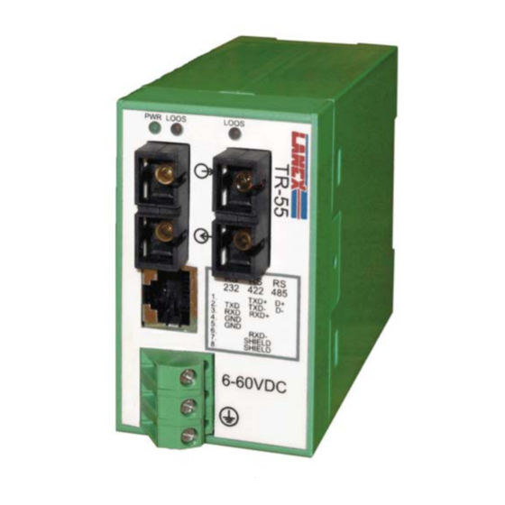
RS-232, RS-422, RS-485 ONVERTER PERATION ANUAL 1. General Characteristics. 1.1. The View of Device Figure 1. The device’s view 1.2. The Intended Use of Device The TR-55 is a device used for point-point connections or connections in bus topology between devices connected to one another with optic fibre and equipped with an interface compatible with the RS-232, RS-422 or RS-485 standards. -
Page 5: Symbol Marking
RS-232, RS-422, RS-485 ONVERTER PERATION ANUAL 1.3. Symbol Marking: TR – 55.W – X – Y (T) T - means the version of the converter which works in extended temperature: -40C ... +75 C optical interface type: 2 – 1310 nm SM/MM 5 –... -
Page 6: Examples Of Different Uses For The Converter
RS-232, RS-422, RS-485 ONVERTER PERATION ANUAL 1.4. Examples of Different Uses for the Converter RS232 RS232 TR-55 TR-55 RS232 RS232, RS422 or TR-55 TR-55 RS485 Driver RS232, RS422 or TR-55 TR-55 RS485 RS422 or RS485 bus Driver Optic single or double-fibre line Two-pair copper wire IOA55-1c August 2009... - Page 7 RS-232, RS-422, RS-485 ONVERTER PERATION ANUAL RS232, RS422 or Driver TR-55 TR-55 TR-55 RS485 RS422 or RS232, RS422 or RS485 bus RS485 Driver Driver Driver RS232, RS422 or TR-55 TR-55 Driver RS485 Driver Driver TR-55 RS422 or Driver RS485 bus Optic single or double-fibre line Two-pair copper wire Converter units operating with protection...
- Page 8 RS-232, RS-422, RS-485 ONVERTER PERATION ANUAL Driver TR-55 TR-55 TR-55 RS422 or RS232, RS422 or RS485 bus RS485 Driver Driver Driver TR-55 TR-55 Driver RS232, RS422 or Driver RS485 Driver RS422 or Driver RS485 bus Optic single or double-fibre line Two-pair copper wire IOA55-1c August 2009...
-
Page 9: Connectors And Signalling Parts
RS-232, RS-422, RS-485 ONVERTER PERATION ANUAL 2. Connectors and signalling parts The following schematics show the front and lower panel view of the TR-55 converter, where connectors and signalling parts have been placed. Optical connectors Optical connectors Transmitter Transmitter Receiver Receiver TXD+ RJ45 signal connector... -
Page 10: Figure 4. Front Panel View Of The Tr-55 Single-Fibre Converter With Two Optical Ports
RS-232, RS-422, RS-485 ONVERTER PERATION ANUAL Transmitter/receiver Transmitter/receiver 1550/1310 1550/1310 Optical connectors Optical connectors Transmitter/receiver Transmitter/receiver 1310/1550 1310/1550 RJ45 signal connector TXD+ TXD- Signal connector and RXD+ power connector RXD- Power connector 6-60V DC SHIELD and ground 6-60 VDC Figure 4. Front panel view of the TR-55 single-fibre converter with two optical ports Optical connector Optical connector TR-55... -
Page 11: Connectors
Figure 6. Lower panel view of the TR-55 converter – all versions 2.1. Connectors 2.1.1. TR-55.1 The device is equipped with the RJ-45 screened connector intended for a two-pair twisted wire. Optic-fibre wire should be connected by the agency of SC-type connectors (double, single for final converter version and two double or single ones for intermediate converter version). -
Page 12: Tr-55.2
RS-232, RS-422, RS-485 ONVERTER PERATION ANUAL The converter should be connected with a cat. 5 twisted wire, of which the impedance of twisted wire pairs is 120 Ω . The maximum wire length to meet the requirements is 1200 m. However, it is not advisable to use such long connections. -
Page 13: Signalling
RS-232, RS-422, RS-485 ONVERTER PERATION ANUAL Signal wire should be connected with a wire, of which the impedance of twisted wire pairs is 120 Ω . The maximum wire length to meet the requirements is 1200 m. However, it is not advisable to use such long connections. -
Page 14: Configuration
RS-232, RS-422, RS-485 ONVERTER PERATION ANUAL 2.3. Configuration Figure 10 shows a DIP-SWITCH together with the numbering types used to configure the device. The converter working modes are shown in Table 2. The first four switches configure the terminator, the next two configure the work of the device with protection, the remaining two configure the standard of the electrical interface. -
Page 15: Functional Description
RS-232, RS-422, RS-485 ONVERTER PERATION ANUAL Protection concerns only devices with two optical interfaces, dip switch configuration of 5 and 6 position does not relevant to operation device with only one optical interface x –Does not affect to configuration 3. Functional Description The TR-55 converter has the following functions: sending and receiving data in the RS-232, RS-422, RS-485 standards, detecting a break in the optic fibre line,... -
Page 16: Bus Termination
4.4.2. The Range of Transmission Along the Optical Path The following example illustrates the calculation of the scope of connection made with the use of single-mode optic fibre of the TR-55.1-1-2 device. Typical fibre loss 9/125 µm 0,4 dB/km... -
Page 17: The Rules Of Use Of Optical Fibre Connectors
SM/MM [dBm] [dBm] [km] [nm] 1310 MM/SM 10/30 TR-55.1/2-1-2(T) TR-55.1/2-1-5(T) 1310/1550 TR-55.1/2-1-6(T) 1550/1310 TR-55.1/2-2-2(T) 1310 1310/1550 and TR-55.1/2-2-7(T) 1550/1310 4.5. The Rules of Use of Optical Fibre Connectors Optic fibre connectors are devices of extremely high precision and require handling with care. -
Page 18: Electrical Parameters Of The Rs-232, Rs-422, Rs-485 Interfaces
Environmental parameter Permissible value Industrial -10 ° C ÷ +55 ° C TR-55.1/2-X-Y Ambient temperature Extreme -40 ° C ÷ +75 ° C TR-55.1/2-X-Y T max 95% in the temperature of +20 ° C Relative air humidity IOA55-1c August 2009... -
Page 19: Transport
RS-232, RS-422, RS-485 ONVERTER PERATION ANUAL 5.4.2 Transport Transport of devices packed in the factory should be done in the following conditions: Table 11. Environmental parameters for transport Environmental parameter Permissible value -40 ÷ +80 ° C Ambient temperature ≤ 10 ° C/h Speed of temperature change Maximum air humidity 700 ÷... - Page 20 RS-232, RS-422, RS-485 ONVERTER PERATION ANUAL IOA55-1c August 2009...
- Page 21 Produced in: Lanex S.A. 8 Ceramiczna Street 20-150 Lublin, Poland tel.: +48 81 444 10 11 fax: +48 81 740 35 70 e-mail: info@lanex.pl web: www.lanex.pl Customer Technical Support Number: tel. +48 81 443-96-39 Lanex S.A. 2009 IOA55-1c August 2009...
Need help?
Do you have a question about the TR-55.1 and is the answer not in the manual?
Questions and answers