Table of Contents
Advertisement
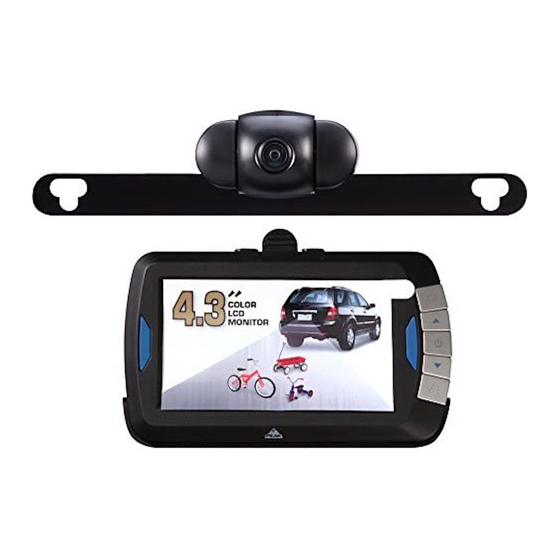
I. Product functions
The product is mainly used for backing or parking a car. It is composed of a transmitter and a receiver, and is
attached with a retaining bracket and the power core.
The transmitter adopts 2.4G Digital wireless backing and rear viewing approach, and the receiver adopts 3.5" LCD
2.4G Digital wireless backing and rear viewing approach. The transmitter shoots the image through CMOS image
sensor and converts such image into digital signal before sending it out, then the receiver restores the received digital
signal into image and displays it on the LCD screen, so that the accuracy and safety are ensured when the driver is
backing or parking a car.
II. Precautions in safety operation of the product
The receiver is installed on the console or windshield of the car. Please install it firmly and keep the LCD screen
free from impacts. The transmitter is installed at the tail of the car and is fastened in a right position. Keep the CMOS
camera clean to ensure that reliable information is provided to the driver.
III. Component list
S/N
Name
1
Receiver
2
Transmitter
3
Retaining
bracket
the receiver
4.
Power core
of
receiver
Wireless Rear View Backup System
PKC0BU4 Tx & PKC0RB Rx
Photo
of
the
Quality
required
1
1
1
1
Advertisement
Table of Contents

Related Manuals for Peak PKC0BU4 Tx

Summary of Contents for Peak PKC0BU4 Tx
- Page 1 Wireless Rear View Backup System PKC0BU4 Tx & PKC0RB Rx I. Product functions The product is mainly used for backing or parking a car. It is composed of a transmitter and a receiver, and is attached with a retaining bracket and the power core.
- Page 2 IV. Product Operation and Signal Instructions 1. Receiver operation: 1.1 Power supply: The receiver uses 12V or 24V DC power supply provided by the car cigar plug socket 1.2 Indicator description The blue indicator is lit when the receiver is powered, and automatically enters the working state. If there is no signal, the receiver automatically turns off LCD, and blue LED indicator flashes;...
- Page 3 Select SETUP to enter pair code selection screen: Press the Up or Down key, select PAIR 1 or PAIR 2, press the Confirm key to enter the pairing state, when appears, the camera transmitter is switched on; press and hold the PAIR key for about 2 seconds,After pairing successfully If there is no operation in 20S or pairing fails, it will resume the previous state.
- Page 4 1.4.2 Master camera selection Channels 1 and 2 can be defined into master camera. In automatic mode, the signal of single camera will be automatically displayed; when two cameras receive signal simultaneously, the master camera has the priority, and the screen will automatically switch to the master camera in 3S. Master camera selection method: Select MASTER in the SETUP menu Icon, press the Confirm key to enter camera selection.
- Page 5 Icon, press the Confirm key to select the camera to Mirror/Rotate, select CAM1 or CAM2, press the Confirm key to enter the Mirror / Rotate state, and the screen shows Icon, press the Confirm key to select the appropriate display direction. 1.4.5 Image screen display settings The display screen can be adjusted in too bright or too dark environment, and the camera of each channel can be adjusted independently,...
- Page 6 Icon, press the Confirm key to enter, press the Up or Down key to select the appropriate display effect. B. Contrast settings, select the contrast Icon, press the Confirm key to enter, press the Up or Down key to select the appropriate display effect.
- Page 7 2. Camera transmitter operation: 2.1 The camera transmitter is installed in the rear side of the car; when used for reversing, please connect to power supply of taillights; if installed in the car, the door can be connected to the power supply of interior lighting, or other 8V-30V DC power supply system.
- Page 8 3. Connect one end of the receiver power cord to the host and plug the other end directly into the cigar lighter power connector,. 4. Install the transmitter at the tail of the car, as shown in the following picture: Note : Cet appareil est conforme à...
- Page 9 supérieur au gain maximal indiqué, sont strictement interdits pour l'exploitation de l'émetteur. Antenna Type : internal permanent antenna Max. Antenna Gain :0dBi To maintain compliance with FCC’s RF exposure guidelines, this equipment should be installed and operated with a minimum distance of 20cm between the radiator and your body.
Need help?
Do you have a question about the PKC0BU4 Tx and is the answer not in the manual?
Questions and answers
Can not get to pair up