Furuno VR-3000 Operator's Manual
Voyage data recorder
simplifed voyage data recorder
Hide thumbs
Also See for VR-3000:
- Installation manual (82 pages) ,
- Instruction manual (57 pages) ,
- Operator's manual (54 pages)

Related Manuals for Furuno VR-3000


Summary of Contents for Furuno VR-3000
- Page 1 OPERATOR'S MANUAL VOYAGE DATA RECORDER SIMPLIFED VOYAGE DATA RECORDER VR-3000 VR-3000S MODEL www.furuno.com...
- Page 2 Nishinomiya, 662-8580, JAPAN A : APR 2006 Printed in Japan All rights reserved. J : JAN . 27, 2012 Pub. No. OME-44370-J *00015707818* *00015707818* (REFU ) VR-3000/3000S *00015707818* *00015707818* * 0 0 0 1 5 7 0 7 8 1 8 *...
- Page 3 (http://www.eiae.org/) for the correct method of disposal. How to discard a used battery Some FURUNO products have a battery(ies). To see if your product has a battery, see the chapter on Maintenance. Follow the instructions below if a battery is used. Tape the + and - terminals of battery before disposal to prevent fire, heat generation caused by short circuit.
- Page 4 Warning labels are attached to the DCU. Do not remove the labels. If the label is missing or parts may result. damaged, contact a FURUNO agent or dealer about replacement. Name: Warning Label 1 WARNING...
- Page 5 POWERING DATA COLLECTING UNIT On the power control panel in the Data Collecting Unit (DCU), confirm that the status display shows “- - -“ and the NORMAL LED is lit after the power has been on for two minutes. If not, see Chapter 3.
- Page 6 If you press the SAVE button on the RAP, one recording area stops recording. If you press the SAVE button four times, all four areas stop recording. If you pressed the SAVE button, consult a FURUNO dealer to restore the HDD after an investigation of the incident is completed by the authorities.
-
Page 7: Table Of Contents
TABLE OF CONTENTS FOREWORD ....................vi SYSTEM CONFIGURATION..............vii Record of PUB REV., PROG. No............. viii 1. OPERATION .................... 1 1.1 Overview ...........................1 1.2 Operating Procedure......................6 1.2.1 Powering, recording......................6 1.2.2 Stopping recording......................6 1.3 Operation on Remote Alarm Panel ...................7 1.4 Removing HDD at an Incident...................8 1.5 How to Release DRU ......................8 2. -
Page 8: Foreword
The basic VR-3000/VR-3000S consists of a Data Collecting Unit (DCU), a Data Recording Unit (DRU), a Remote Alarm Panel (RAP) and microphones to record bridge audio. The VR-3000 is also equipped with a Junction Box (JB), which is optional on the VR-3000S. The DCU contains the Data Processor Unit, interface modules and backup batteries. -
Page 9: System Configuration
SYSTEM CONFIGURATION Data Recording Unit (DRU) VR-5020-6G/VR-5020-9G Waterproof MIC VR-3012W Bridge MIC Max. 6 ch VR-5011 Remote Alarm Max. VHF I/F 2 ch Panel (RAP) IF-5200 Junction Box (JB) VR-3016 24 VDC VHF Audio IF-8530 (max. 2) Max. 2 ch Data Collecting Serial Serial (Max. -
Page 10: Record Of Pub Rev., Prog. No
RECORD OF PUB REV., PROG. NO. Revision No., Program No. Outline of Revision Date of Revision (software) VR-3000 SYSTEM printing. Apr. 19, 2006 2450031-01 2450026-01 Revised system configuration drawings to include Same as above Waterproof MIC. June 2, 2006 Changed error code no. as follows: 035→034 Storage failure... -
Page 11: Operation
VHF communication audio Power supply precaution If ship’s mains power source (100-230 VAC) and emergency source fail, the VR-3000/VR-3000S continues to record bridge audio for 2 h from backup batteries. When using the backup batteries, suspend power to the IF-8530 Junction box.. - Page 12 Continuity of storing data The VDR should be provided with power to store data for 12 h on a first-in, first-out basis. Recording is terminated only under the following circumstances: a) During essential maintenance while the vessel is in port. b) When the vessel is laid-up.
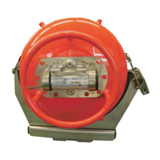
- Page 13 Data Recording Unit The Data Recording Unit is housed in a highly visible protective capsule which can withstand a fire of 1100°C for 1 hour and deep-sea pressure of 6000 m. The underwater acoustic beacon (pinger) on the capsule automatically transmits 10 ms pulses at 37.5 kHz for at least 30 days when it is submerged in water.
- Page 14 AIS-VHF data-link message, AIS-VHF data-link own-vessel message Where there is no commercial off-the-shelf interface available to obtain radar data then AIS target data shall be recorded as a source of information regarding other ships, otherwise AIS information may be recorded additionally as a beneficial secondary source of information on both other and own ship.
- Page 15 Radar data Radar image including range rings, EBLs, VRMs, plotting symbols, radar maps, parts of SENC, voyage plan, and other essential navigational indications, is recorded in the DRU via the interface in the DCU which is connected to the buffered video output of the radar display unit. One complete picture frame is captured at intervals of 15 s.
-
Page 16: Operating Procedure
1.2 Operating Procedure The VDR comes with a key to lock the DCU to protect against any unauthorized access. The key must be kept securely after installation. 1.2.1 Powering, recording On the power control panel in the DCU, turn on the AC SUPPLY MAINS, DC SUPPLY MAINS and BATTERY BACK-UP switches in this order. -
Page 17: Operation On Remote Alarm Panel
If you press the SAVE button four times, all four areas stop recording. To remove the HDD, see paragraph 1.4. If you pressed the SAVE button during an incident, consult a FURUNO dealer to restore the HDD after the authorities complete an investigation of the incident. -
Page 18: Removing Hdd At An Incident
1.4 Removing HDD at an Incident VDR information is copied automatically into the backup hard disk drive (HDD) for more than 12 hours (max. 13 hours) and is then automatically written over with new data. Bring the HDD with you after an incident if possible. Press the SAVE button only when an incident occurs. To replace the HDD under other circumstances, see section 2.6. -
Page 19: Maintenance
2. MAINTENANCE Periodic checks and maintenance are important for proper operation of any electronic systems. This chapter contains maintenance instructions to be followed to obtain optimum performance and the longest possible life of the equipment. Any maintenance must be executed by a suitably qualified technician. -
Page 20: Software Maintenance
2.3 Software Maintenance 2.3.1 Software list The software and software version of the VR-3000/VR-3000S are as shown in the table below. VR-3000/VR-3000S software list Software name Software version Date VR-3000 System Program 2450031-02 July 2008 VR-3000 RAP 2450026-01 Mar 2006 2.3.2 Checking software version of system program... -
Page 21: Replacing Batteries
Every four years, the back-up batteries (2 pcs.) in the DCU must be replaced with new ones (Type: OP24-12 Code no.: 004-385-010) by a qualified service engineer. Note that the batteries should be recycled. Contact a FURUNO dealer for further details. Observe the following precautions with the batteries:... -
Page 22: Replacing Acoustic Beacon
2.5 Replacing Acoustic Beacon The life of the underwater acoustic beacon is approximately 6 years. It must be replaced (Type: DK-120, Code no. 000-148-648) by a qualified service technician before validity date marked on the beacon. 1. Unfasten two bolts and remove the beacon cover. 2. -
Page 23: Replacing Backup Hdd
An HDD may not be re-used for recording after the Save button has been operated four times. Contact a FURUNO dealer for further details. A backup HDD records navigation data for more than past 12 hours (48 hours max). For longer recording, use Live Player V4. -
Page 24: Replacing Fuses
2.7 Replacing Fuses The battery cable in the DCU contains two 10A fuses in fuse holders. If a fuse blows, the BACKUP BATTERY LED may not be lighting. Find the cause before replacing a fuse. Have a serviceman replace any fuse. Fuses 2.8 Replacing Parts Interval-specific parts... -
Page 25: Verifying Recording Function Of The Dru
2.9 Verifying Recording Function of the DRU Verify the DRU’s recording function at the annual inspection and when repairing or maintaining the VDR or sensors connected to the VDR. The verification requires the Live Player V4. Refer to its Operator's Manual for the operating procedure. Note that data cannot be extracted during recording. 1. -
Page 26: Confirmation Of Peripheral Devices
2.10 Confirmation of Peripheral Devices Confirm the data from serial signal output devices, analog signal output devices and contact signal output devices. To do this, connect the PC to the DCU and use the Live Player software. Serial signal output devices The threshold levels of the time-out for serial signal input are preset. -
Page 27: Troubleshooting
3. TROUBLESHOOTING This chapter provides information on possible causes of problems you may experience with your VDR. If you still have a problem after referring to the table, contact your local dealer or national distributor for further advice. Always provide the product serial number. 3.1 General Troubleshooting Use the table below to identify the trouble, cause and possible solution. -
Page 28: Error Codes
120 seconds. and repair or replace. GPS Large Time This indicates that the time Restart VR-3000/S. Try to see if the CMOS Difference difference between system time and clock is set correctly. If not, set it and time supplied by UTC source is restart VR-3000/S. - Page 29 082+084 Fatal system Failure Fatal system error. This indicates Reboot VR-3000/S manually. If VR-3000/S (RAP=082, that VR-3000/S can not be rebooted does not recover, request service. AP=084) automatically. Note: After switching to battery drive (error code 214), this error may occur. The error disappears and the system recovers after AC and/or DC power is reconnected.
- Page 30 BaukupHDD Bad BackupHDD memory device failure. Restart VDR. If error occurs again, request Sector Full service. DUR Exchanged This indicates that DRU is replaced. Restart VR-3000/S. Backup HDD This indicated that backup HDD is Restart VR-3000/S. Exchanged replaced. Frame Grabber Radar interface board is available Request service.
-
Page 31: Testing Display Of Remote Alarm Panel
Request service to reformat BackupHDD. Failure BackupHDD format is out of order. Fatal System Failure Fatal system error. This indicates Restart VDR manually. If VR-3000/S does that VR-3000/S can not be rebooted not recover, request service. automatically. VDR System VDR system information can not be... -
Page 32: Location Of Parts
4. LOCATION OF PARTS 4.1 Parts Location 4.1.1 Data Collecting Unit (VR-3010) Fuses From top: 1) RADAR I/F Board (RI-3010) Battery 2) AUDIO Board (OP24-12) 3) SERIAL Board (2 pcs.) 4) Riser Card (24P0068) 5) CPU Board Backup Hard Disk (HDD) (VR-3011-A) Compact Flash Card... -
Page 33: Data Recording Unit (Vr-5020-9G Or Vr-5020-6G)
4.1.2 Data Recording Unit (VR-5020-9G or VR-5020-6G) CONNECTOR Board FLASH DISK Board (24P0042) (FW-ATA2501-1) Underwater Acoustic Beacon (DK-120) CONNECTION Board (24P0087) 2.5-inch FLASH DISK (SLFLD25-8GM1U1 (for 6G) or DK0090G88TNO (for 9G)) REPEATER Board (24P0080) (Firewire cable connects to CONNECTOR Board.) Components inside capsule Data Recording Unit (VR-5020-9G or VR-5020-6G) -
Page 34: Junction Box (If-8530)
4.1.3 Junction Box (IF-8530) MAIN Board (24P0069) Terminal Board (24P0077) (w/WAGO connectors) Junction Box (IF-8530) 4.1.4 Remote Alarm Panel (VR-3016) RAP PANEL Board (24P0076A) (underneath) RAP MAIN Board (24P0075A) (underneath) Remote Alarm Panel (VR-3016) -
Page 35: Parts List
(IMO A.694(17)/8.3.1. Only some discrete components are used. FURUNO Electric Co., Ltd. believes identifying these components is of no value for shipborne maintenance; therefore, they are not listed in this manual. Major modules can be located on the parts location on previous pages. -
Page 36: Interface (Iec 61162-1, Iec 61162-2)
5. INTERFACE (IEC 61162-1, IEC 61162-2) 5.1 Data Sentences ALA - Set detail alarm condition $xxALA, hhmmss.ss, aa, aa, xx, xxx, A, A, c—c *hh<CR><LF> 1) Event time Event time of alarm condition change includeing acknowledgement state change. If this is not available, this shouled be a null field. - Page 37 DOR - Door status indication This sentence indicates the status of watertight doors, fire doors and other hull openings / doors. $xxDOR, A, hhmmss.ss, aa, cc, xxx, xxx, a,a, c—c *hh<CR><LF> 6 7 8 9 1) Message type S: Status for section: the number of faulty and/or open doors reported in the division specified in field 4 and 5.
- Page 38 DPT - Depth IMO Resolution A.224 (VII). Water depth relative to the transducer and offset of the measuring transducer. Positive offset numbers provide the distance from the transducer to the waterline. Negative offset numbers provide the distance from the transducer to the part of the keel of interest.
- Page 39 ETL - Engine telegraph operation status The ETL sentence indicates engine telegraph position including operating location and sub-telegraph indicator. $xxETL, hhmmss.ss, a, xx, xx, a, x, *hh<cr><lf> 3 4 5 6 0) Header 1) Event Time 2) Indicator of command O = Order A = Answerback 3) Position indication of engine telepgraph...
- Page 40 FIR - Fire detection $xxFIR, A, hhmmss.ss, aa, cc, xxx, xxx, a, a, c--c, *hh<CR><LF> 1) Message type S: Status for section: the number of faulty and activated condition reported as number in field 6.The section may be a whole section (one or both of the division indicator fields are null) or a sub-section. The status S is normally transmitted at regular intervals.
- Page 41 GEN - Generic status information This sentence provides a means of transmitting multi-sensor generic status information from any source, in a format that can be registered by the VDR. The sentence is designed for efficient use of the bandwidth and must be accompanied with a description of how to interpret the information.
- Page 42 GNS - GNSS fix data Fix data for single or combined satellite navigation systems (GNSS). 3 4 5 9 10 11 6 7 8 $--GNS,hhmmss.ss,llll.lll,a,yyyyy.yyy,a,c--c,xx,x.x,x.x,x.x,x.x,x.x,a*hh<CR><LF> 1) UTC of position 2) Latitude, N/S 3) Longitude, E/W 4) Mode indicator Mode indicator. A variable length valid character field type with the first three characters currently defined. The first character indicates the use of GPS satellites, the second character indicates the use of GLONASS satellites and the third indicate the use of Galileo satellites.
- Page 43 fields should be provided in following GNS sentences with talker Ids of GP, GL, etc. These following GNS messages should have the latitude, N-S, longitude, E/W, altitude, geoidal separation, mode, and HDOP fields null. This indicates to the listener that the field is supporting a previous $GNGNS sentences to denote the number of satellites used from that satellite system.
- Page 44 HDG - Heading Magnetic $--HDG,x.x,x.x,a,x.x,a*hh<CR><LF> | | | | | +--------- 4 | +--+----------- 3 | +----+----------------- 2 +------------------------ 1 1. Magnetic sensor heading, degrees 2. Magnetic deviation, degrees E/W 3. Magnetic variation, degrees E/W 4. Checksum HDT - Heading True $--HDT, x.x, T*hh<CR><LF>...
- Page 45 HTC - Heading/Track control command $--HTC,A,x.x,a,a,a,x.x,x.x,x.x,x.x,x.x,x.x,x.x,a*hh<CR><LF> | | | | | | | | | | | | | +--- 14 | | | | | | | +----- 13 | | | | | | | +-------- 12 | | | | | | | +------------ 11 | | | | | | | +---------------- 10...
- Page 46 HTD - Heading/Track control data $--HTD,A,x.x,a,a,a,x.x,x.x,x.x,x.x,x.x,x.x,x.x,a,A,A,A,x.x*hh<CR><LF> | | | | | | | | | | | | | | | | | | | | | | | +--- 18 | | | | | | | | | | | +------ 17 | | | | | | | | | | +--------- 16 | | | | | |...
- Page 47 MWV - Wind speed and angle When the reference field is set to relative, data is provided giving the wind angle in relation to the vessel’s heading and wind speed, both relative to the moving vessel. When the reference field is set to true, data is provided giving the wind angle relative to the vessel’s heading and wind speed, both with reference to the moving water.
- Page 48 RPM - Revolutions Shaft or engine revolution rate and propeller pitch. $--RPM, a, x, x.x, x.x, A*hh<CR><LF> Status: A = data valid Propeller pitch, % of maximum, “-” = astern Speed, revolutions/min, “-” = counter-clockwise Engine of shaft number, numbered from center-line Odd = starboard, even = port, 0 = single or no center-line Source, shaft/engine S/E RSA - Rudder sensor angle...
- Page 49 TRD - Thruster response data This sentence provides the response data for thruster devices. $xxTRD, x, x.x, A, x.x, A, x.x, *hh<cr><lf> 1 2 3 0) Header 1) Number of thrusters Odd = Bow thruster Even = Stern thruster 2) RPM demand 3) Data status R = relative (%): 0-100% from zero to maximum rpm T = true (deg)
- Page 50 VDM - UAIS VHF Data-link Message (IEC 61162-2, for AIS) !--VDM,x,x,x,x,s--s,x*hh<CR><LF> | | | | | | | | | +--- 7 | | | | | +----- 6 | | | | +-------- 5 | | | +------------ 4 | | +-------------- 3 | +---------------- 2 +------------------ 1...
- Page 51 WAT - Water level detection This sentence provides detection status of water leakage and bilge water level, with monitoring location data. Malfunction alarm of the water level detector should be included in the “ALA” sentence. $xxWAT, A, hhmmss.ss, aa, aa, xx, xxx, A, c—c, *hh<cr><lf> 1 2 3 4 5 6 7 8 9 0) Header 1) Message type...
- Page 52 XDR - Transducer measurements Measurement data from transducers that measure physical quantities such as temperature, force, pressure, frequency, angular or linear displacement, etc. Data from a variable number of transducers measuring the same of different quantities can be mixed in the same sentence. This sentence is designed for use by integrated systems as well as transducers that may be connected in a “chain”...
-
Page 53: Interface Circuits
5.2 Interface Circuits 5.2.1 IEC 61162-1 Data Collecting Unit Junction Box... -
Page 54: Iec 61162-2
5.2.2 IEC 61162-2 Data Collecting Unit Junction Box... -
Page 55: Appendix: Playing Back Recorded Data
July 2006 be supplied with an accessible means for extracting the stored data from the VDR or S-VDR to a laptop computer. Manufacturers are required to provide software for extracting data, instructions for extracting data and cables for connection between recording device and computer. FURUNO provides the following: •... -
Page 56: Specifications
July 2002 by the revised SOLAS Chapter V. The Simplified Voyager Data Recorder (S-VDR) is a recording system required by IMO MSC.163(78). VR-3000 fully complies with the IMO Resolution A. 861 (20) and IEC 61996 testing standard. VR-3000S fully complies with the IMO MSC.163(78) and IEC/PAS 61996 testing standard. - Page 57 FURUNO VR-3000/VR-3000S Shock Resistance 50G x 11 ms Penetration Resistance 100 m diameter pin w/250 kg weight, dropped from 3 m height Fire Resistance 1100°C for 1 hour, 260°C for 10 hours Submersible 6000 m (60 Mpa) Acoustic Beacon Replaced every 6 years, max. depth 6000 m, 30 days 37.5 kHz 10 ms pulse transmission...
Need help?
Do you have a question about the VR-3000 and is the answer not in the manual?
Questions and answers