Table of Contents
Advertisement
Quick Links
TM
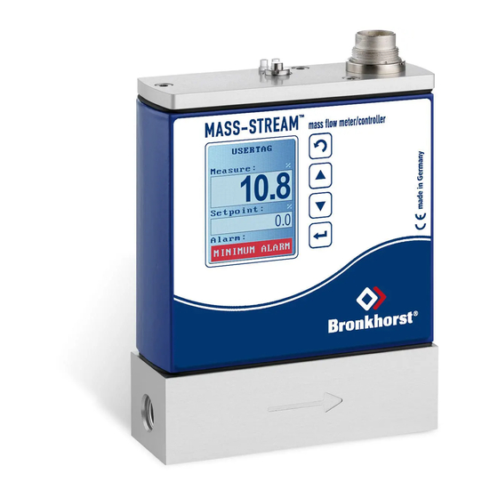
MASS-STREAM
Instruction Manual
D-6300/FS
Digital Mass Flow Meter as Flow Switch
Doc. No.: 9.17.114A Date: 27-07-2017
ATTENTION
Before installing and operating the instrument it is strongly recommended
that this instruction manual should be read carefully. Not following the
guidelines could result in personal injury and/or damage to the equipment.
Advertisement
Table of Contents

Related Manuals for BRONKHORST D-6300/FS


Summary of Contents for BRONKHORST D-6300/FS
- Page 1 MASS-STREAM Instruction Manual D-6300/FS Digital Mass Flow Meter as Flow Switch Doc. No.: 9.17.114A Date: 27-07-2017 ATTENTION Before installing and operating the instrument it is strongly recommended that this instruction manual should be read carefully. Not following the guidelines could result in personal injury and/or damage to the equipment.
- Page 2 ® Bronkhorst Flow Switch instruments, a special product of the D-6300 Mass-Stream series. Benefitting from the multi-functional display the D-6300/FS flow switches allow the adjustment of an individual switch-point according to the mass flow of a gas or gas-mix. ®...
- Page 3 Repairs are normally warranted for one year or the balance of the original warranty, whichever is the longer. See also paragraph A-V and B-II of the Terms and Conditions of sales of the M+W Instruments GmbH. MASS-STREAM Manual Flow Switch D-6300/FS Page 3 of 36 9.17.114A – edition: 2017-07...
- Page 4 M+W Instruments GmbH, these costs are added to the repair invoice. Import and/or export charges, foreign shipping methods/carriers are paid for by the customer. MASS-STREAM Manual Flow Switch D-6300/FS Page 4 of 36 9.17.114A – edition: 2017-07...
-
Page 5: Table Of Contents
Table of Contents SHORT FORM START-UP………………..............6 FLOW SWITCH INSTRUMENTS D-6300/FS............7 2.1 General……......................7 2.2 Installation....................... 9 2.3 Operation and Maintenance................. 10 2.4 Output Variants of the Switch-Point……….…….………………………..……….. 11 2.4.1 Variant 1 „OFF – ON – OFF“……..……………………………………….… 12 2.4.2 Variant 2 „ON – OFF – ON“…..…..……………………………………….… 13 2.5 Setting of the Switch-Point using the Multi-functional Display.…...……...….. -
Page 6: Short Form Start-Up
Baud rate = 38400 Baud, no parity, 8 data bits, 1 stop bit. ® In case of any trouble during installation or to set up the communication Bronkhorst programs like FlowDDE or HyperTerminal (available in MS-Windows) could be very useful. Please refer to chapter 4 how to use FlowDDE. -
Page 7: Flow Switch Instruments D-6300/Fs
FLOW SWITCH INSTRUMENTS D-6300/FS 2.1 General The digital D-6300/FS Flow Switch instruments of M+W Instruments GmbH are thermal measurement devices for mass flow, where the alarm function of the multi-functional display is used for the adjustment of an individual switch-point depending on the mass flow of a gas or gas-mix. - Page 8 The declaration of decontamination is available on our accompanying CD with each instrument shipment or it can be downloaded from our website www.bronkhorst.com. Please mention the instrument’s model code and the serial number on your order, as well as your VAT number when needed.
-
Page 9: Installation
(D-6380/FS and bigger) in another mounting position you should get in contact with your distributor or with M+W Instruments GmbH beforehand. MASS-STREAM Manual Flow Switch D-6300/FS Page 9 of 36 9.17.114A – edition: 2017-07... -
Page 10: Operation And Maintenance
Be sure that the specified pressure ratings have been applied. Pressure surges, as may occur during the system pressurisation, must be avoided. When starting up, always bring the instrument gradually up to the level of operating conditions. MASS-STREAM Manual Flow Switch D-6300/FS Page 10 of 36 9.17.114A – edition: 2017-07... -
Page 11: Output Variants Of The Switch-Point
2.4 Output Variants of the Switch-Point The digital D-6300/FS Flow Switches provide 3 different setting options in 2 different switching variants. The required variant for the referring instrument configuration needs to be determined with the Flow Switch order. -
Page 12: Variant 1 „Off - On - Off
2.4.1.a Maximum Alarm „OFF – ON – OFF“ Display shows Alarm : Red LED Pin 5 2.4.1.b Minimum Alarm „OFF – ON – OFF“ Display shows Alarm : Red LED Pin 5 MASS-STREAM Manual Flow Switch D-6300/FS Page 12 of 36 9.17.114A – edition: 2017-07... -
Page 13: Variant 2 „On - Off - On
Red LED Pin 5 2.4.2 Variant 2 „ON – OFF – ON“ 2.4.2.a Maximum Alarm „ON – OFF – ON“ Display shows Alarm : Red LED Pin 5 MASS-STREAM Manual Flow Switch D-6300/FS Page 13 of 36 9.17.114A – edition: 2017-07... - Page 14 2.4.2.b Minimum Alarm „ON – OFF – ON“ Display shows Alarm : Red LED Pin 5 2.4.2.c Minimum-Maximum Alarm „ON – OFF – ON“ Display shows Alarm Red LED Pin 5 MASS-STREAM Manual Flow Switch D-6300/FS Page 14 of 36 9.17.114A – edition: 2017-07...
-
Page 15: Setting Of The Switch-Point Using The Multi-Functional Display
The factory settings for the password are „abc“ plus 5 blanks. A description how to store an individual password can be found in the Mass-Stream Instruction Manual D-6300 Multi-functional Display (document no. 9.17.105). MASS-STREAM Manual Flow Switch D-6300/FS Page 15 of 36 9.17.114A – edition: 2017-07... - Page 16 • Select required letters or figures with Up and Down and confirm each selection with Enter. 1 x Up Enter 2 x Up Enter 3 x Up Enter 5 x Enter MASS-STREAM Manual Flow Switch D-6300/FS Page 16 of 36 9.17.114A – edition: 2017-07...
-
Page 17: Basis Settings In The ʹAlarmʹ Menu
(see example) ʹDelayʹ-factory setting: „0“ (see page 18) ʹSetpoint stepʹ-factory setting: „no“ (FIX – do not change!) 1 x Down ʹSetpointʹ-factory setting: „0.0“ (FIX – do not change!) MASS-STREAM Manual Flow Switch D-6300/FS Page 17 of 36 9.17.114A – edition: 2017-07... -
Page 18: Example For Switch-Point Settings „Minimum-Maximum-Alarm
Pin 5 when the flow rate drops below „27.8 l /min“. • Maximum Switch-Point: 45 l /min 100% flow rate 38.5 l /min maximum switch-point flow rate MASS-STREAM Manual Flow Switch D-6300/FS Page 18 of 36 9.17.114A – edition: 2017-07... - Page 19 Pin 5 when the flow rate exceeds „38.5 l /min“. • Input of the Switch-Points via the Multi-functional display Select Min alarm with Down and activate this menu item with Enter: Down Enter MASS-STREAM Manual Flow Switch D-6300/FS Page 19 of 36 9.17.114A – edition: 2017-07...
- Page 20 Up and Down in the menu item Min alarm and activated with Enter: 4 x Down Enter 1 x Up Enter 2 x Down Enter 1 x Down Enter MASS-STREAM Manual Flow Switch D-6300/FS Page 20 of 36 9.17.114A – edition: 2017-07...
- Page 21 ʹ85.6%ʹ are now set with Up and Down in the menu item Max alarm and activated with Enter: Enter Enter 2 x Down Enter 5 x Up Enter 4 x Down Enter MASS-STREAM Manual Flow Switch D-6300/FS Page 21 of 36 9.17.114A – edition: 2017-07...
-
Page 22: Adjustment Of The Alarm-Reset Function „Automatic ↔ Manual
Max alarm and the data in Min alarm remains ʹ0.0 ʹ. 2.5.4 Adjustment of the Alarm-“Reset” Function: automatic ↔ manual 1 x Up / Down Enter 2 x Back Enter MASS-STREAM Manual Flow Switch D-6300/FS Page 22 of 36 9.17.114A – edition: 2017-07... -
Page 23: Specifications Of Mass-Stream
155 mA at 100% flow 0…10 Vdc / 0…5 Vdc active Output signal 0…20 mA / 4…20 mA active Instrument connector 8-pin round DIN(male) for analogue and RS232 MASS-STREAM Manual Flow Switch D-6300/FS Page 23 of 36 9.17.114A – edition: 2017-07... -
Page 24: Hook-Up Diagram Rs232 And Analog I/O, 8-Pole Round (Male)
2.6.1 Hook-up diagram RS232 and Analog I/O, 8-pole round (male) MASS-STREAM Manual Flow Switch D-6300/FS Page 24 of 36 9.17.114A – edition: 2017-07... -
Page 25: 8Din Connector, 8-Pole Round (Female)
Be sure that the integrity of the shielding is not affected when connecting the system to other devices (e.g. to PLC). Only shielded wire terminals can be used. MASS-STREAM Manual Flow Switch D-6300/FS Page 25 of 36 9.17.114A – edition: 2017-07... -
Page 26: Measurement Principle And Calibration
+ C · Φ P … Heater power … Heater power offset at zero flow C … Constant (device-dependent) … Mass flow Φ n … dimensionless figure (type 0.5) MASS-STREAM Manual Flow Switch D-6300/FS Page 26 of 36 9.17.114A – edition: 2017-07... -
Page 27: Functional Block Diagram
The reading is also available as 2-byte integer at parameter 8 and can be readout via RS232. MASS-STREAM Manual Flow Switch D-6300/FS Page 27 of 36 9.17.114A – edition: 2017-07... -
Page 28: Calibration And Look-Up Table
Design of a Look-up Table Index Raw signal X Standardized value Y … … … MASS-STREAM Manual Flow Switch D-6300/FS Page 28 of 36 9.17.114A – edition: 2017-07... -
Page 29: Operation Via Rs232
− Start of FlowDDE and select the COM-Port connected to the instrument. Set the Arbitration to “Autobusmaster + optimize“, then select “Parameter“ and “Process“ in the menu ʹChainingʹ. MASS-STREAM Manual Flow Switch D-6300/FS Page 29 of 36 9.17.114A – edition: 2017-07... - Page 30 ‚F3’ or by clicking on the menu ʹCommunicationʹ, being followed by a second click on ʹOpen communicationʹ. FlowDDE on your monitor should show the following picture: MASS-STREAM Manual Flow Switch D-6300/FS Page 30 of 36 9.17.114A – edition: 2017-07...
-
Page 31: Input Signal Via Flowview
Alarm functions (configurable) Counter functions (configurable) … Operations procedure − Start FlowDDE and open the communication − Start FlowView − The following pictures should be displayed (example) MASS-STREAM Manual Flow Switch D-6300/FS Page 31 of 36 9.17.114A – edition: 2017-07... - Page 32 The adjustment of alarm functions is well supported by FlowView. Click on the button ʹAlarm & Counterʹ to open a frame for the adjustment of all settings. MASS-STREAM Manual Flow Switch D-6300/FS Page 32 of 36 9.17.114A – edition: 2017-07...
- Page 33 MASS-STREAM Manual Flow Switch D-6300/FS Page 33 of 36 9.17.114A – edition: 2017-07...
-
Page 34: Manual Interface: Micro Switches And Led's
This can be realised by pressing the switch first and while pressing, connecting the power. These actions have a more ‘initialising’ character for the instrument. MASS-STREAM Manual Flow Switch D-6300/FS Page 34 of 36 9.17.114A – edition: 2017-07... - Page 35 See specific fieldbus for more details flash 0.1 sec off Critical error message continuously A serious error occurred in the instrument Instrument needs service before further using MASS-STREAM Manual Flow Switch D-6300/FS Page 35 of 36 9.17.114A – edition: 2017-07...
- Page 36 Special mode for fieldbus applications – 12 – 16 sec wink wink Not relevant for Flow Switch instruments Please note: normal flash = 0.2 sec on / 0.2 sec off MASS-STREAM Manual Flow Switch D-6300/FS Page 36 of 36 9.17.114A – edition: 2017-07...
Need help?
Do you have a question about the D-6300/FS and is the answer not in the manual?
Questions and answers