Table of Contents
Advertisement
Getting Started
Chapter 1
Getting Started
Thank you for choosing the MS-7502 Series Micro-ATX
mainboard. The MS-7502 Series mainboards are based
®
on Intel
G33 & ICH9DH chipsets for optimal system
®
efficiency. Designed to fit the advanced Intel
Core 2
Quad/Core 2 Duo/ Dual-Core (E2xxx) LG A775
processor, the MS-7502 Series deliver a high perfor-
mance and professional desktop platform solution.
1-1
Advertisement
Table of Contents

Related Manuals for MSI MS-7502 Series


Summary of Contents for MSI MS-7502 Series
- Page 1 Getting Started Chapter 1 Getting Started Thank you for choosing the MS-7502 Series Micro-ATX mainboard. The MS-7502 Series mainboards are based ® on Intel G33 & ICH9DH chipsets for optimal system ® efficiency. Designed to fit the advanced Intel Core 2...
-
Page 2: Mainboard Specifications
M S-7502 M ainboard Mainboard Specifications Processor Support ® - Intel Core 2 Quad/Core 2 Duo/Dual-Core(E2xxx) processors in the LGA775 package Supported FSB - 1333/ 1066/ 800 MHz Chipset ® - North Bridge: Intel G33 chipset ® - South Bridge: Intel ICH9DH chipset M emory Support - DDR2 800/ 667 SDRAM (8GB Max) - Page 3 Getting Started Connectors Back panel - 1 PS/2 mouse port - 1 PS/2 keyboard port - 1 Serial port - 6 USB 2.0 Ports - 1 1394 port - 1 LAN jack (10/100) - 5 flexible audio jacks - 1 Optical SPDIF-Out port - 1 Coaxial SPDIF-Out port On-Board Pinheaders / Connectors - 3 USB 2.0 pinheaders...
-
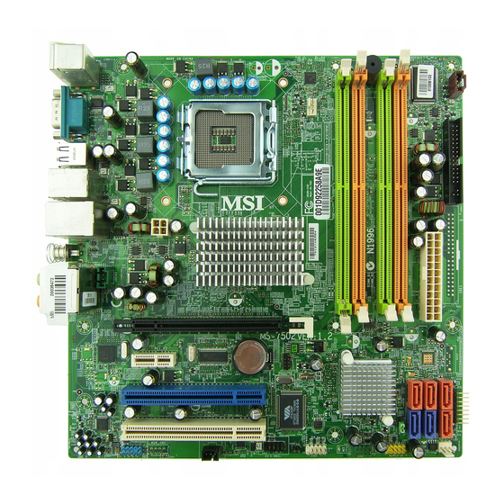
Page 4: Mainboard Layout
T:CS-Out M:RS-Out B:SPDIF-Out PCI_E1 PCI_ E2 L AN CHI P BATT Marvel l CHIP PCI 1 Intel ICH9DH PCI 2 VT6308P Codec JBAT1 J1394_1 JSPD1 JUSB3 JUSB1 JAU D1 CD_IN 1 JUSB2 JSMI1 SYSFAN1 MS-7502 Series (MS-7502 v1.X) Micro-ATX Mainboard... -
Page 5: Hardware Setup
Hardware Setup Chapter 2 Hardware Setup This chapter provides you with the information about hardware setup procedures. While doing the installation, be careful in holding the components and follow the installation procedures. For some components, if you install in the wrong orientation, the components will not work properly. -
Page 6: Quick Components Guide
M S-7502 M ainboard Quick Components Guide CPUFAN, p.2-14 JPW1, p.2-9 DDR2 DIMMs, CPU, p.2-3 p.2-7 JVFD1, p.2-16 FDD1, p.2-12 Back Panel, p.2-10 JPWR3, p.2-9 JSCA1, p.2-13 SATA1~6, p.2-12 PCI_E Slots, p.2-19 JFP1, p.2-13 PCI Slots, p.2-19 S Y S F A N 1 , p.2-14 JSPD1, JUSB1~3,... -
Page 7: Introduction To Lga 775 Cpu
Hardware Setup CPU (Central Processing Unit) W hen you are installing the CPU, make sure to install the cooler to prevent overheating. If you do not have the CPU cooler, consult your dealer before turning on the computer. Important Overheating Overheating will seriously damage the CPU and system. -
Page 8: Cpu & Cooler Installation
M S-7502 M ainboard CPU & Cooler Installation W hen you are installing the CPU, make sure the CPU has a cooler attached on the top to prevent overheating. Meanwhile, do not forget to apply some thermal paste on CPU before installing the heat sink/cooler fan for better heat dispersion. Follow the steps below to install the CPU &... - Page 9 Hardware Setup 5. Lift the load lever up and open the 6. After confirming the CPU direction load plate. for correct mating, put down the CPU in the socket housing frame. Be sure to grasp on the edge of the CPU base. Note that the align- ment keys are matched.
- Page 10 M S-7502 M ainboard 9. Press down the load lever lightly 10. Align the holes on the mainboard onto the load plate, and then se- with the heatsink. Push down the cure the lever with the hook under c ooler u nti l i ts f ou r c lip s g et retention tab.
-
Page 11: Dual-Channel Mode Population Rule
Hardware Setup Memory These DIMM slots are used for installing memory modules. DDR2 240-pin, 1.8V 56x2=112 pin 64x2=128 pin Dual-Channel mode Population Rule In Dual-Channel mode, the memory modules can transmit and receive data with two data bus lines simultaneously. Enabling Dual-Channel mode can enhance the system performance. -
Page 12: Installing Memory Modules
M S-7502 M ainboard Installing Memory Modules 1. The memory module has only one notch on the center and will only fit in the right orientation. 2. Insert the memory module vertically into the DIMM slot. Then push it in until the golden finger on the memory module is deeply inserted in the DIMM slot. -
Page 13: Power Supply
Hardware Setup Power Supply ATX 24-Pin Power Connector: JPWR3 pin 13 This connector allows you to connect an ATX 24-pin power supply. To connect the ATX 24-pin power supply, make sure the plug of the power supply is inserted in the proper orientation and the pins are aligned. -
Page 14: Back Panel
M S-7502 M ainboard Back Panel 1394 Port M ou se Line-Out CS-Out Serial Port SS-Out RS-Out Line-In Optical SPDIF-out Coaxial Keyboard USB Ports USB Ports SPDIF-out M ouse/Keyboard ® ® The standard PS/2 mouse/keyboard DIN connector is for a PS/2 mouse/keyboard. - Page 15 Hardware Setup Coaxial S/PDIF-Out This SPDIF (Sony & Philips Digital Interconnect Format) connector is provided for digital audio transmission to external speakers through a coaxial cable. Audio Ports These audio connectors are used for audio devices. You can differentiate the color of the audio jacks for different audio sound effects.
- Page 16 M S-7502 M ainboard Connectors Floppy Disk Drive Connector: FDD1 This connector supports 360KB, 720KB, 1.2MB, 1.44MB or 2.88MB floppy disk drive. Serial ATA Connector: SATA1 ~ SATA6 This connector is a high-speed Serial ATA interface port. Each connector can connect to one Serial ATA device.
-
Page 17: Scart Output Connector: Jsca1
Hardware Setup SCART Output Connector: JSCA1 This connector allows you to connect the output device with SCART spec. SCART is the established European standard for connecting home video equipments like TVs, VCRs, DVD players, etc. Front Panel Connectors: JFP1 The mainboard provides one front panel connector for electrical connection to the ®... -
Page 18: Fan Power Connectors: Cpufan1, Sysfan1
M S-7502 M ainboard Fan Power Connectors: CPUFAN1, SYSFAN1 The fan power connectors support system cooling fan with +12V. W hen connecting the wire to the connectors, always note that the red wire is the positive and should be connected to the +12V; the black wire is Ground and should be connected to GND. If the mainboard has a System Hardware Monitor chipset on-board, you must use a specially designed fan with speed sensor to take advantage of the CPU fan control. - Page 19 Hardware Setup IEEE1394 Connector: J1394_1 This connector allows you to connect the IEEE1394 device via an optional IEEE1394 bracket. Pin Definition SIGNAL SIGNAL TPA+ TPA- Ground Ground TPB+ TPB- Cable power Cable power Key (no pin) Ground S/PDIF-Out Connector: JSPD1 This connector is used to connect S/PDIF (Sony &...
-
Page 20: Front Panel Audio Connector: Jaud1
M S-7502 M ainboard Front Panel Audio Connector: JAUD1 This connector allows you to connect the front panel audio and is compliant with ® Intel Front Panel I/O Connectivity Design Guide. HD Audio Pin Definition SIGNAL DESCRIPTION MIC_L Microphone - Left channel Ground MIC_R Microphone - Right channel... -
Page 21: Front Usb Connector: Jusb1
Hardware Setup Front USB Connector: JUSB1 ~ 3 ® These connectors, compliant with Intel I/O Connectivity Design Guide, is ideal for connecting high-speed USB interface peripherals such as USB HDD, digital cameras, M P3 players, printers, modems and the like. Pin Definition SIGNAL SIGNAL... - Page 22 M S-7502 M ainboard Jumper Clear CMOS Jumper: JBAT1 There is a CMOS RAM onboard that has a power supply from an external battery to keep the data of system configuration. W ith the CMOS RAM, the system can auto- matically boot OS every time it is turned on.
-
Page 23: Pci (Peripheral Component Interconnect) Express Slot
Hardware Setup Slots PCI (Peripheral Component Interconnect) Express Slot The PCI Express slot supports the PCI Express interface expansion card. The PCI Express x 16 supports up to 4.0 GB/s transfer rate. The PCI Express x 1 supports up to 250 MB/s transfer rate. PCI Express x16 Slot PCI Express x1 Slot PCI (Peripheral Component Interconnect) Slot...
Need help?
Do you have a question about the MS-7502 Series and is the answer not in the manual?
Questions and answers