Table of Contents
Advertisement
9 PORTS 10/100/1000BASE-T MANAGEMENT ETHERNET
8 PORTS 10/100/1000BASE-T MANAGEMENT ETHERNET
SWITCH WITH 1 PORT 1000BASE-X UPLINK OR 1 PORT
8 PORTS 10/100/1000BASE-T MANAGEMENT ETHERNET
SWITCH WITH 1 PORT 1000BASE-X UPLINK OR 1 PORT
100/1000BASE-X UPLINK AND TV RF RECEIVER
8 PORTS 10/100/1000BASE-T MANAGEMENT ETHERNET
SWITCH WITH 1 PORT 1000BASE-X UPLINK OR 1 PORT
100/1000BASE-X UPLINK WITH BATTERY CHARGING
8 PORTS 10/100/1000BASE-T MANAGEMENT ETHERNET
SWITCH WITH 1 PORT 1000BASE-X UPLINK OR 1 PORT
100/1000BASE-X UPLINK WITH BATTERY CHARGING
FUNCTION AND TV RF RECEIVER
HES-3109 SERIES
SWITCH
100/1000BASE-X UPLINK
FUNCTION
Network Management
User's Manual
Version 0.91
1
Advertisement
Table of Contents

Related Manuals for CTS HES-3109

Summary of Contents for CTS HES-3109
-
Page 1: Network Management
HES-3109 SERIES 9 PORTS 10/100/1000BASE-T MANAGEMENT ETHERNET SWITCH 8 PORTS 10/100/1000BASE-T MANAGEMENT ETHERNET SWITCH WITH 1 PORT 1000BASE-X UPLINK OR 1 PORT 100/1000BASE-X UPLINK 8 PORTS 10/100/1000BASE-T MANAGEMENT ETHERNET SWITCH WITH 1 PORT 1000BASE-X UPLINK OR 1 PORT 100/1000BASE-X UPLINK AND TV RF RECEIVER... - Page 2 Trademarks CTS is a registered trademark of Connection Technology Systems Inc. Contents subject to revise without prior notice. All other trademarks remain the property of their owners. Copyright Statement Copyright Connection Technology Systems Inc. This publication may not be reproduced as a whole or in part, in any way whatsoever unless prior consent has been obtained from Connection Technology Systems Inc.
-
Page 3: Table Of Contents
Table of Content 1. INTRODUCTION ....................... 5 1.1 Interfaces ........................5 1.2 Management Preparations ................... 7 1.2.1 Connecting the Management Ethernet Switch ............7 1.2.2 Assigning IP Addresses ..................7 1.3 LED Definitions......................8 1.4 Button Definitions ......................9 2. Command Line Interface (CLI) ..................10 2.1 Remote Console Management-Telnet ................ - Page 4 2.5.11 Switch command ....................34 2.5.12 Switch-info command ..................34 2.5.13 User command ....................36 2.5.14 VLAN command ....................37 2.5.15 Show interface statistics command ..............39 2.5.16 Show sfp command ................... 39 2.5.17 Show running-config & start-up-config command ..........40 APPENDIX A: Set Up DHCP Auto-Provisioning ...............
-
Page 5: Introduction
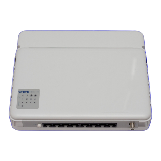
1. INTRODUCTION Thank you for using the 8-Port 10/100/1000Base-T plus 1-Port 1000Base-X Uplink or 100/1000Base-X & 9-Port 10/100/1000Base-T Management Ethernet Switch. The built-in management module allows users to configure this Switch and monitor the operation status locally or remotely through network. The Management Ethernet Switch is fully compliant with IEEE 802.3 and 802.3u standards. - Page 6 1000Mbps F/O port CATV RF Input Battery Charging (Optional) (Optional) Figure 4. Rear Panel for 8-Port 10/100/1000Base-T plus 1-Port 1000Base-X or 100/1000Base-X Uplink Management Ethernet Switch with optional CATV RF & Battery Charging module All models have the same top, left and right panel. LED Indicators Figure 5.
-
Page 7: Management Preparations
1.2 Management Preparations The Management Ethernet Switch can be accessed through both Telnet connection and a web browser (will be available in later Firmware version), such as Internet Explorer or Netscape, etc. Before you can access to the Management Ethernet Switch to configure it, you need to connect cables properly. -
Page 8: Led Definitions
assigns a globally unique network number to each network that wishes to connect to the Internet. The second part (XXX.XXX.8.100 in the example) identifies the device within the network. Assigning unique device numbers is your responsibility. If you are unsure of the IP addresses allocated to you, consult the allocation organization from which your IP addresses were obtained. -
Page 9: Button Definitions
1.4 Button Definitions Button Operation Push this button to turn on or off LED indicators. Smart Lighting Control When it is turned on, system status LED and port link LEDs Button will be turned off. Only power and battery discharging LED indicators remain on. -
Page 10: Command Line Interface (Cli)
2. Command Line Interface (CLI) This chapter introduces you how to use Command Line Interface (CLI) via Telnet connection, specifically in: Configuring the system Resetting the system Upgrading newly released firmware 2.1 Remote Console Management-Telnet You can use Command Line Interface to manage the Management Ethernet Switch via Telnet session. -
Page 11: Navigating Cli
2.2 Navigating CLI When you successfully access the Management Ethernet Switch, you will be asked for a login username. Enter your authorized username and password, and then you will be directed to User mode. In CLI management, the User mode only provides users basic functions to operate the Management Ethernet Switch. -
Page 12: Quick Keys
2.2.2 Quick Keys In CLI, there are several quick keys that you can use to perform several functions. The following table summarizes the most frequently used quick keys in CLI. Keys Purpose Enter an unfinished command and press “Tab” key to complete the command. - Page 13 The following table lists common symbols and syntax that you will see very frequently in this User’s Manual for your reference: Symbols Brief Description > Currently, the device is in User mode. Currently, the device is in Privileged mode. (config)# Currently, the device is in Global Configuration mode.
-
Page 14: Login Username & Password
2.2.4 Login Username & Password Default Login When you enter Telnet session, a login prompt for username and password will appear to request a valid and authorized username and password combination. For first-time users, enter the default login username “admin” and “press Enter key” in password field (no password is required for default setting). -
Page 15: User Mode
2.3 User Mode In User mode, only a limited set of commands are provided. Please note that in Use mode, you have no authority to configure advanced settings. You need to enter Enable mode and Configuration mode to set up advanced functions of a switch feature. For a list of commands available in User mode, enter the question mark (?) or “help”... - Page 16 Switch# copy-cfg [A.B.C.D] Enter the IP address of your TFTP server. from tftp [A.B.C.D] [file_name] Enter the configuration file name that you [file_name] want to restore. Example Switch# copy-cfg from ftp 192.168.1.198 HS_0600_file.conf misadmin1 abcxyz Switch# copy-cfg from tftp 192.168.1.198 HS_0600_file.conf 2.
-
Page 17: Firmware Command
2.4.2 Firmware command To upgrade Firmware via FTP or TFTP server. Command Parameter Description Switch# firmware [A.B.C.D] Enter the IP address of your FTP server. upgrade ftp [file_name] Enter the firmware file name that you want to [A.B.C.D] upgrade. [file_name] [user_name] Enter the username for FTP server login. -
Page 18: Configure Command
2.4.5 Configure command The only place where you can enter Global Configuration mode is in Privileged mode. You can type in “configure” or “config” for short to enter Global Configuration mode. The display prompt will change from “Switch#” to “Switch(config)#” once you successfully enter Global Configuration mode. -
Page 19: Entering Interface Numbers
2.5.1 Entering Interface Numbers In the Global Configuration mode, you can configure a command that only apply to interfaces specified. For example, you can set up each interface’s VLAN assignment, speeds, or duplex modes. To configure, you must first enter the interface number. There are four ways to enter your interface numbers to signify the combination of different interfaces that apply to a command or commands. - Page 20 Company Name: Display a company name for this Management Ethernet Switch. Use “switch-info company-name [company-name]” command to edit this field. System Object ID: Display the predefined System OID. System Contact: Display contact information for this Management Ethernet Switch. Use “switch-info sys-contact [sys-contact]” command to edit this field. System Name: Display a descriptive system name for this Management Ethernet Switch.
-
Page 21: Interface Command
3. Display interface information or statistics Refer to “show interface statistics command” and “show sfp information command” sections. 4. Show running and startup configurations Refer to “show running-config command” and “show start-up-config command” sections. 2.5.4 Interface command Use this command to set up various port configurations of discontinuous or a range of ports. Command Parameter Description... -
Page 22: Catv Command
Switch(config-if-PORT-PORT)# no media-type Set the uplink port back to the default media type (copper). Switch(config-if-PORT-PORT)# no shutdown Administratively enable the selected ports’ status. Show command Switch(config)# show interface status Show each interface’s port status including media type, forwarding state, speed, duplex mode, flow control and link up/down status. -
Page 23: Ip Command
2.5.6 IP command 1. Set up or remove the IP address of the Management Ethernet Switch. IP command Parameter Description Switch(config)# [A.B.C.D] Enter the desired IP address for your Switch. ip address [255.X.X.X] Enter subnet mask of your IP address. [A.B.C.D] [A.B.C.D] Enter the default gateway address. - Page 24 When IGMP snooping is enabled in a switch it analyses all the IGMP packets between hosts connected to the switch and multicast routers in the network. When a switch hears an IGMP report from a host for a given multicast group, the switch adds the host's port number to the multicast list for that group.
-
Page 25: Mac Command
4. Enable or disable IGMP snooping immediate-leave function. This works only when IGMP Snooping is enabled. When Immediate Leave is enabled, the Switch immediately removes the port when it detects IGMPv1 & IGMPv2 leave message on that port. Command / Example Description Switch(config)# ip igmp snooping Enable IGMP immediate leave function. -
Page 26: Qos Command
2.5.8 QoS command 1. Specify the desired QoS mode. QoS command Parameter Description Switch(config)# qos [port- [port-based | Specify one QoS mode. based | 802.1p | dscp] 802.1p | dscp] port-based: Use “interface” and “qos default-class” command to assign a queue to the selected interfaces. - Page 27 3. Set up QoS queuing mode. Queuing-mode command Parameter Description Switch(config)# qos queuing- [weight] By default, “strict” queuing mode is used. mode [weight] If you want to use “weight” queuing mode, you need to disable “strict” queuing mode. Strict mode: This indicates that services to each egress queues are offered based on rates specified.
- Page 28 Show command Switch(config)# show qos Show or verify QoS configurations. 802.1p-map example Switch(config)# qos 802.1p- Map priority bit 6 and 7 to queue 4. map 6-7 3 Switch(config)# no qos Delete or remove 802.1p priority bit 6 and 7’s mapping. 802.1p-map 6-7 5.
-
Page 29: Security Command
Switch(config)# show qos Show or verify QoS configurations. QoS & Interface example Switch(config)# interface 1-3 Enter several discontinuous port numbers separating by a comma or a range of ports with a hyphen. For example:1,3 or 2-4 Switch(config-if-1-3)# qos rate-limit ingress Configure the selected interfaces’... - Page 30 Switch(config-if-PORT-PORT)# no security Disable unknown multicast storm storm-protection unknown-multicast protection. Switch(config-if-PORT-PORT)# no security Disable unknown unicast storm storm-protection unknown-unicast protection. Show command Switch(config)# show security [port_list] Show the selected interfaces’ security storm-protection interface settings and storm control rates. [port_list] Switch(config)# show security storm- Show each interface’s security settings protection interface including storm control rates.
-
Page 31: Snmp-Server Command
2.5.10 SNMP-Server command 1. Create a SNMP community and set up detailed configurations for this community. Snmp-server command Parameter Description Switch(config)# snmp- [community] Specify a SNMP community name of up to server community 20 alphanumeric characters. [community] Switch(config-community- Enable this SNMP community account. NAME)# active Switch(config-community- [Description]... - Page 32 Exit command Switch(config-community-NAME)# exit Return to Global Configuration mode. Snmp-server example Switch(config)# snmp-server community Create a new community “mycomm” and mycomm edit the details of this community account. Switch(config-community-mycomm)# active Activate the SNMP community “mycomm”. Switch(config-community-mycomm)# Add a description for “mycomm” description rddeptcomm community.
- Page 33 Exit command Switch(config- trap-ACCOUNT)# exit Return to Global Configuration mode. Trap-destination example Switch(config)# snmp-server trap- Create a trap destination account. destination 1 Switch(config-trap-1)# active Activate the trap destination account. Switch(config-trap-1)# community Refer this trap destination account to the mycomm community “mycomm”. Switch(config-trap-1)# description Add a description for this trap destination redepttrapdest...
-
Page 34: Switch Command
Show command Switch(config)# show snmp-server trap- Show the current enable/disable status of type each type of trap. Trap-type example Switch(config)# snmp-server trap-type all All types of SNMP traps will be sent. 2.5.11 Switch command Switch command Description Switch(config)# switch sfp polling Enable the Switch to refresh SFP DMI information and current state in a fixed interval. - Page 35 Switch(config)# switch- [system_name] Enter a unique name for this Managed info system-name Switch, up to 55 alphanumeric characters. [system_name] Use a descriptive name to identify the Managed Switch in relation to your network, for example, “Backbone 1”. This name is mainly used for reference only. Switch(config)# switch- [host_name] Enter a new hostname for this...
-
Page 36: User Command
2.5.13 User command Create a new login account. User command Parameter Description Switch(config)# user name [user_name] Enter the new account’s username. The [user_name] authorized user login name is up to 20 alphanumeric characters. Only 3 login accounts can be registered in this device. Switch(config-user- Activate this user account. -
Page 37: Vlan Command
Switch(config-user-USERNAME)# show Show or verify the newly-created user account’s information. User command example Switch(config)# user name miseric Create a new login account “miseric”. Switch(config-user-USERNAME)# Add a description to this new account description misengineer “miseric”. Switch(config-user-USERNAME)# level Set this new account’s access privilege to “read &... - Page 38 Switch(config-if-PORT-PORT)# Set the selected ports to trunk mode (tagged). vlan dot1q-vlan mode trunk Switch(config-if-PORT-PORT)# Enable native VLAN for untagged traffic. vlan dot1q-vlan mode trunk native No command Switch(config)# no vlan dot1q- [1-4094] Delete the specified VID. vlan [1-4094] Switch(config)# no vlan qinq- Disable Q-in-Q VLAN.
-
Page 39: Show Interface Statistics Command
2.5.15 Show interface statistics command “show interface statistics” that can display port traffic statistics, port packet error statistics and port analysis history can be used either in Privileged mode # and Global Configuration mode (config)#. “show interface statistics” is useful for network administrators to diagnose and analyze port traffic real-time conditions. -
Page 40: Show Running-Config & Start-Up-Config Command
2.5.17 Show running-config & start-up-config command Command Description Switch(config)# show running-config Show configurations currently used in the Managed Switch. Please note that you must save running configurations into your switch flash before rebooting or restarting the device. Switch(config)# show start-up-config Display system configurations that are stored in flash. -
Page 41: Appendix A: Set Up Dhcp Auto-Provisioning
APPENDIX A: Set Up DHCP Auto-Provisioning Networking devices, such as switches or gateways, with DHCP Auto-provisioning function allow you to automatically upgrade firmware and configuration at startup process. Before setting up DHCP Server for auto-upgrade of firmware and configuration, please make sure the Managed Switch that you purchased can support DHCP Auto-provisioning. - Page 42 Step 2. Set up Auto Provision Server Update DHCP Client Linux Fedora 12 supports “yum” function by default. First of all, update DHCP client function by issuing “yum install dhclient” command. Install DHCP Server Issue “yum install dhcp” command to install DHCP server.
- Page 43 Copy dhcpd.conf to /etc/dhcp/ directory Copy dhcpd.conf file provided by the vendor to /etc/dhcp/ directory. Please note that each vendor has their own way to define auto provisioning. Make sure to use the file provided by the vendor. Enable and run DHCP service 1.
- Page 44 Step 3. Modify dhcpd.conf file Open dhcpd.conf file in /etc/dhcp/ directory Double-click dhcpd.conf placed in /etc/dhcp/ directory to open it.
- Page 45 Modify dhcpd.conf file The following marked areas in dhcpd.conf file can be modified with values that work with your networking environment. 1. Define DHCP default and maximum lease time in seconds. Default lease time: If a client does not request a specific IP lease time, the server will assign a default lease time value.
- Page 46 5. This value is configurable and can be defined by users. 6. Specify the protocol used (Protocol 1: FTP; Protocol 0: TFTP). 7. Specify the FTP or TFTP IP address. 8. Login TFTP server anonymously (TFTP does not require a login name and password). 9.
- Page 47 Restart DHCP service...
- Page 48 Every time when you modify dhcpd.conf file, DHCP service must be restarted. Issue “killall dhcpd” command to disable DHCP service and then issue “dhcpd” command to enable DHCP service. Step 4. Backup a Configuration File Before preparing a configuration file in TFTP/FTP Server, make sure the device generating the configuration file is set to “Get IP address from DHCP”...
- Page 49 B. Auto-Provisioning Process This switching device is setting-free (through auto-upgrade and configuration) and its upgrade procedures are as follows: 1. The ISC DHCP server will recognize the device whenever it sends an IP address request to it. And ISC DHCP server will tell the device how to get a new firmware or configuration. 2.
- Page 50 This page is intentionally left blank. Revision History Manual Version Modification Firmware Version Date 0.91 The initial version. 0.99.1J 2011/06 NOTE: This User’s Manual is written or revised according to the officially-released Firmware version. The content of this Manual is subject to change without prior notice.
Need help?
Do you have a question about the HES-3109 and is the answer not in the manual?
Questions and answers