Table of Contents
Advertisement
OWNER'S MANUAL
MODELS:
FOR YOUR SAFETY:
DO NOT STORE OR USE GASOLINE OR OTHER
FLAMMABLE VAPORS OR LIQUIDS IN THE
VICINITY OF THIS OR ANY OTHER APPLIANCE.
IMPORTANT:
POST INSTRUCTIONS IN A PROMINET
LOCATION TO BE FOLLLOWED IN THE EVENT
THE USER SMELLS GAS. THIS INFORMATION
SHALL BE OBTAINED BY CONSULTING THE
LOCAL GAS SUPPLIER.
Form Number: S-2404 REV. F
Printed in USA
Gas Operated Boilers
□
M24G100A-4SP
□
M36G100A-4SP
□
M36G300A-4SP
05/13
Telephone (617) 387-4100, (866) 698-3188, Fax (617) 387-4456, (800) 227-2659
□
M24G200A-4SP
□
M36G200A-4SP
WARNING:
IMPROPER INSTALLATION, ADJUSTMENT,
ALTERATION, SERVICE OR MAINTENANCE CAN CAUSE
PROPERTY DAMAGE, INJURY OR DEATH. READ THESE
INSTALLATION, OPERATION AND MAINTENANCE
INSTRUCTIONS THOROUGHLY BEFORE INSTALLING
OR SERVICING THIS EQUIPMENT.
35 Garvey Street, Everett, MA 02149
custserv@mfii.com, www.mfii.com
0
Advertisement
Table of Contents

Related Manuals for Market Forge Industries M24G100A-4SP


Summary of Contents for Market Forge Industries M24G100A-4SP
- Page 1 OWNER’S MANUAL Gas Operated Boilers □ □ MODELS: M24G100A-4SP M24G200A-4SP □ □ M36G100A-4SP M36G200A-4SP □ M36G300A-4SP WARNING: FOR YOUR SAFETY: IMPROPER INSTALLATION, ADJUSTMENT, DO NOT STORE OR USE GASOLINE OR OTHER ALTERATION, SERVICE OR MAINTENANCE CAN CAUSE FLAMMABLE VAPORS OR LIQUIDS IN THE PROPERTY DAMAGE, INJURY OR DEATH.
-
Page 2: Table Of Contents
Table of Contents INTRODUCTION ............................. 2 To the Kitchen Manager: .......................... 2 INSTALLATION INSTRUCTIONS ........................3 GAS OPERATED BOILERS ........................... 3 INSTALLING LEGS: ............................. 3 LEVELING: ..............................3 LOWER DEFLECTOR PLATE: ........................3 GAS SERVICE CONNECTIONS: * ......................... 4 ELECTRIC SERVICE CONNECTION: * ......................4 SERVICE CONNECTIONS: ........................... -
Page 3: Introduction
INTRODUCTION To the Kitchen Manager: 1. Read this manual carefully and in its entirety. Contact Market Forge Ind., Inc. for clarification if necessary. 2. Protect your kitchen personnel from scalding and other serious injury by providing training programs to acquaint all equipment operators with the correct and safe methods of operation. -
Page 4: Installation Instructions
INSTALLATION INSTRUCTIONS GAS OPERATED BOILERS MODELS: • M24G100A - 4SP • M24G200A - 4SP • M36G100A - 4SP • M36G200A - 4SP • M36G300A - 4SP CAUTION: BE SURE TO READ: Keep this appliance area free and clear from combustibles. Do not obstruct the flow of combustion and ventilation air. -
Page 5: Gas Service Connections
INSTALLATION INSTRUCTIONS GAS SERVICE CONNECTIONS: * a) The boiler is factory adjusted for a gas input of 100, 200 & 300K BTU/HR at the pressure indicated. Please read the rating plate behind the Lift-Off Front Panel. If this plate is marked for a different gas than that supplied, notify your dealer immediately. -
Page 6: Service Connections
INSTALLATION INSTRUCTIONS SERVICE CONNECTIONS: Gas Operated Gas Connection - 3/4” (19mm) IPS (100 & 200K BTU) Gas Connection - 1” (25mm) IPS (275 & 300K BTU) Cold Water - 3/8” (10mm) O.D. tubing for cold water to boiler. Cold water lines will have a max of 50PSI (3.5 kg/cm ) and a min of 25PSI (1.8 kgcm... -
Page 7: Lower Deflector Assembly
INSTALLATION INSTRUCTIONS LOWER DEFLECTOR ASSEMBLY LOWER DEFLECTOR 200K Boiler 98-3972 300K Boiler 98-3976 UPPER DEFLECTOR 200K Boiler 94-5115 300K Boiler 94-5095 To Install the Lower Deflector as shown in Figure 1., the following steps must be taken: 1. Locate lower deflector as shown in Figure 2. The rear brackets will slide in openings and allow it to rest in place on frame. -
Page 8: Control Panel
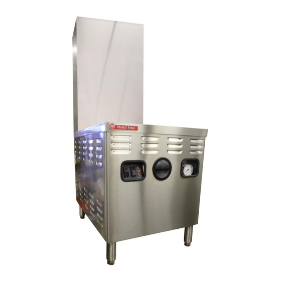
OPERATING INSTRUCTIONS CONTROL PANEL: MODELS: • M24G100A - 4SP • M24G200A - 4SP • M36G100A - 4SP • M36G200A - 4SP • M36G300A - 4SP OPERATING THE STEAM GENERATOR: OPERATING INSTRUCTIONS OPERATING INSTRUCTIONS FOR STEAM GENERATORS OPERATING INSTRUCTIONS FIRST CHECK TO BE SURE THAT: A. -
Page 9: Caution: Be Sure To Read
OPERATING INSTRUCTIONS CAUTION: BE SURE TO READ: Disconnect The Power Supply to the boiler before servicing or cleaning. Keep the appliance area free and clear of combustibles. Do not obstruct the flow of combustion and ventilation air. ... -
Page 10: Setting The Boiler Control Pressure Switches
ADJUSTMENTS SETTING THE BOILER CONTROL PRESSURE SWITCHES: PRESSURE CONTROL SWITCH ADJUSTMENT: If boiler fails to maintain steam pressure in operating range, pressure control switch may require adjustment. 1. Start boiler and allow pressure to build up to operating level - 7 PSI (1kg/cm²). 2. -
Page 11: General Trouble Shooting
GENERAL TROUBLE SHOOTING TROUBLE POSSIBLE CAUSE REMEDY Pilot will not ignite or does not a. Gas not reaching unit. a. Check to make sure gas is b. Main “gas cock knob” not in hold. on and gas line is purged of ON position. - Page 12 GENERAL TROUBLE SHOOTING TROUBLE POSSIBLE CAUSE REMEDY Boiler fails to reach full operating a. Pressure gauge reads a. Replace. pressure of 5 lbs. or 15 lbs. inaccurately. b. Follow instructions for b. Pressure control and high readjusting (page 9). limit control switches are out c.
-
Page 13: Testing Procedure
TESTING PROCEDURE WATER CONTROL BOARD TESTING PROCEDURE RESET LW2 FW - HIGH This test procedure is to be used LED 1 to determine if the control is working properly. LED 2 intended to determine why the control may have failed. If testing shows that the control is LED 3 operating... -
Page 14: Illustrated Parts List
ILLUSTRATED PARTS LIST BOILER BASE - 24” ITEM NO. PART NO. DESCRIPTION 91-8892 Flue Outer, 24” Front 91-8938 Flue Outer, 36” Front 91-8893 Flue Outer, 24” Back 91-2713 Flue Outer, 36” Back 98-0593 Flue Inner Assembly, 100 & 200k Boiler 91-8936 Flue Inner Assembly, 300k Boiler 08-5894... -
Page 15: Pressure Switch Box, Without Cover
ILLUSTRATED PARTS LIST PRESSURE SWITCH BOX, WITHOUT COVER ITEM NO. PART NO. DESCRIPTION 94-5064 Box, Pressure Switch 10-8410 Pressure Switch, Hi-Limit 10-8411 Pressure Switch, Operating 98-3875 Switch, Drain By-Pass 08-7933 Manifold, Pressure Switches 10-4804 Pressure Gauge 09-4844 Union Elbow, 1/2”... -
Page 16: Control Box Asembly, With & Without Cover
ILLUSTRATED PARTS LIST CONTROL BOX ASEMBLY, WITH & WITHOUT COVER ITEM NO. PART NO. DESCRIPTION 08-6549 Switch, Power 94-5127 Switch, Manual Reset 10-5052 Light, Red 08-6450 Transformer, 120-240V 98-1680 Board, Water Level Control 94-5022 Ignition Module 08-6472 Relay Tube 08-6475 Relay Base 98-3877 Relay Bracket... -
Page 17: Plumbing, Left Side Gas Boiler - 24
ILLUSTRATED PARTS LIST PLUMBING, LEFT SIDE GAS BOILER – 24” ITEM NO. PART NO. DESCRIPTION 10-0239 Hose, Drain 1” 10-4137 Clamp Hose 91-6927 Box Drain Assembly 10-7955 Valve, Safety, 15 PSI 10-1058 Valve, Cold Water Condenser, 120V 10-1311 Valve, Drain, 120V 08-4822 Valve, Boiler Feed 08-7959... -
Page 18: Front View Gas Boiler, 200K - 24
ILLUSTRATED PARTS LIST FRONT VIEW GAS BOILER, 200K – 24” ITEM NO. PART NO. DESCRIPTION 08-4900 Water Inlet, Manual Valve 94-5023 Gas Valve 94-5033 Gas Manifold, 100K & 200K Boilers 94-5034 Gas Manifold, 300K Boilers 10-3661 Drain Valve, Manual 10-1311 Drain Valve, Automatic 91-5112 Probe Plate Assy... -
Page 19: Gas Train, 200K Gas Boiler
ILLUSTRATED PARTS LIST GAS TRAIN, 200K GAS BOILER ITEM NO. PART NO. DESCRIPTION 98-3923 Vent, Bleeder 08-7970 Bleeder Hose 10-7955 Valve, Safety, 15 PSI 91-7031 Probe Plate 08-4413 Gasket, Probe Plate 08-6399 Probe, Lowest Probe KIT; Part No. 91-5112 08-6398 Probe 08-6364 Probe... -
Page 20: Gas Train, 200K Gas Boiler
ILLUSTRATED PARTS LIST GAS TRAIN, 200K GAS BOILER ITEM NO. PART NO. DESCRIPTION 08-7832 Tube, Flex, Gas Line 10-1154 Compression Coupling 98-3890 Pilot Tube 94-5099 Spark Pilot and Igniter 94-5129 Pilot Orifice, Prop. 94-5046 Burner 94-5052 Pilot Brkt 08-7119 Orifice, Natural Gas (Brass #30) 08-7120 Orifice, Propane (#45 Black) 08-7118... -
Page 21: Electrical Information
ELECTRICAL INFORMATION Wiring Diagram for New Generation Boilers – 100K, 200K, 300K BTU... -
Page 22: Schematic Diagram For New Generation Boilers - 100K, 200K, 300K Btu
ELECTRICAL INFORMATION Schematic Diagram for New Generation Boilers – 100K, 200K, 300K BTU... -
Page 23: Maintenance
MAINTENANCE Cleaning the Boiler: Market Forge recommends that the boiler be cleaned periodically due to impurities introduced through the water supply. All water supplies contain some mineral deposits and impurities; the degree varies with geographic location. Market Forge is recommending a cleaning schedule that will keep your equipment in proper, safe working order where water supplies are relatively pure. - Page 24 MAINTENANCE 3. Clean rust, scale and lime deposits from the inside of the boiler with a wire brush. DO NOT DAMAGE COPPER HEATING ELEMENTS - BRUSH LIGHTLY. WORK DEPOSITS TO REAR CORNER AND REMOVE WITH PUTTY KNIFE. 4. After removing all debris, flush out with clean water through the hand-hole and drain . 5.
-
Page 25: Application Instructions
APPLICATION INSTRUCTIONS Application Instructions for Total Concept Descaler Cleaning of the Boiler Size: Case of 4 -1 Gallon Bottles / Part No. 20-0307 or 1-1 Gallon Bottle / Part No. 20-0307X GENERAL NOTES: Market Forge R has two basic types of boilers; Figure 1 one has an automatic drain valve, the other has a manual drain valve. - Page 26 APPLICATION INSTRUCTIONS Application Instructions for Total Concept Descaler Cleaning of the Boiler Size: Case of 4 -1 Gallon Bottles / Part No. 20-0307 or 1-1 Gallon Bottle / Part No. 20-0307X Figure 5 Figure 8 NOTE: A minimum of 12” must be inserted. 4.
Need help?
Do you have a question about the M24G100A-4SP and is the answer not in the manual?
Questions and answers