Table of Contents
Advertisement
Quick Links
Download this manual
See also:
Manual
InteliDrive
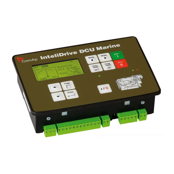
InteliDrive DCU Marine
Expandable engine controller
with electronic engines support
Single speed applications
Variable speed application
SW version 2.2.2, June 2015
Copyright © 2004-2015 ComAp s.r.o.
Written by Ladislav Kadanik, Pavel Doubek
Prague, Czech Republic
AUX, EME, CMB
PRP
Reference guide
ComAp a.s.
Kundratka 2359/17, 180 00 Praha 8, Czech Republic
Tel: +420 246 012 111, Fax: +420 266 316 647
E-mail: info@comap.cz, www.comap.cz
Advertisement
Table of Contents

Subscribe to Our Youtube Channel
Related Manuals for ComAp InteliDrive DCU Marine


Summary of Contents for ComAp InteliDrive DCU Marine
- Page 1 Variable speed application SW version 2.2.2, June 2015 Reference guide ComAp a.s. Copyright © 2004-2015 ComAp s.r.o. Kundratka 2359/17, 180 00 Praha 8, Czech Republic Written by Ladislav Kadanik, Pavel Doubek Tel: +420 246 012 111, Fax: +420 266 316 647 Prague, Czech Republic E-mail: info@comap.cz, www.comap.cz...
-
Page 2: Table Of Contents
Binary inputs on Inteli IO8/8 ........................- 56 - Binary outputs on IS-BIN16/8........................- 56 - Binary outputs on Inteli IO8/8 ........................- 56 - Binary output separation ......................... - 57 - ID-DCU-MARINE-2.2.2, ©ComAp – June 2015 - 2 - ID-DCU-MARINE-2.2.2.pdf... - Page 3 How to find active alarms? ........................- 122 - Main screen indication .......................... - 123 - Controller screens ..........................- 124 - Functions available from ID-DCU MARINE front panel keys ..............- 128 - ID-DCU-MARINE-2.2.2, ©ComAp – June 2015 - 3 - ID-DCU-MARINE-2.2.2.pdf...
- Page 4 IGL-RA15 .............................. - 165 - IGS-PTM ............................... - 166 - I-AOUT8 ..............................- 167 - I-RBxx ..............................- 167 - I-LB+ ..............................- 167 - IG-IB ..............................- 167 - InternetBridge-NT ..........................- 168 - ID-DCU-MARINE-2.2.2, ©ComAp – June 2015 - 4 - ID-DCU-MARINE-2.2.2.pdf...
-
Page 5: Abbreviations
InteliDrive controller. ID-COM InteliDrive communication module with interface to J1939, J1587 and to other controllers. ID-DCU MARINE InteliDrive DCU Marine controller. ID-MCU InteliDrive DCU Marine controller with Volvo Penta front panel modification. ID-DCU-MARINE-2.2.2, ©ComAp – June 2015 - 5 - ID-DCU-MARINE-2.2.2.pdf... - Page 6 Printed Circuit Board PSID J1939 Proprietary Parameter Identification Assignments. RS232 Standard serial data line for PC or Modem connection (controller programming or monitoring). Shut down protection. J1939 Subsystem Identification Assignments. Warning protection. ID-DCU-MARINE-2.2.2, ©ComAp – June 2015 - 6 - ID-DCU-MARINE-2.2.2.pdf...
-
Page 7: General Description
General description InteliDrive DCU Marine is a specialized engine controller for Marine applications. It controls, monitors and protects the engine in single (Auxiliary) or variable (propulsion) speed operational modes. The controller can communicate with Engine Management System via the CAN serial line using standard J1939 or another (KWP2000) communication protocol. -
Page 8: Physical Component And Interface Descriptions
Note: ComAp believes that all information provided herein is correct and reliable and reserves the right to update at any time. ComAp does not assume any responsibility for its use unless otherwise expressly undertaken. Physical component and interface Descriptions Module... -
Page 9: Corresponding Documentation
Alarm list reading in text form via MODBUS (registers 46669 .. 47068) History reading via MODBUS (registers 46357, 46493 .. 46541, 46543 .. 46667) All other ID-DCU Marine functions AirGate WebSupervisor basic description in this Reference Guide. ID-DCU-MARINE-2.2.2, ©ComAp – June 2015 - 9 - ID-DCU-MARINE-2.2.2.pdf... -
Page 10: Terminal And Dimensions
Right GREEN Engine running indication Light when engine is running. Left GREEN Indication of Binary output Light when output is Closed. Close load state Hint: Please check the last software version. ID-DCU-MARINE-2.2.2, ©ComAp – June 2015 - 10 - ID-DCU-MARINE-2.2.2.pdf... -
Page 11: Id-Dcu Marine Terminals
ID-DCU-Industrial-LT version contains a preheating foil on the display activated below +5°C (measured on the PCB). Heating is switched off when controller power supply is below 10VDC Board temperature (together with display backlight). - 40 °C +5 °C ID-DCU-MARINE-2.2.2, ©ComAp – June 2015 - 11 - ID-DCU-MARINE-2.2.2.pdf... -
Page 12: Id-Rpu Terminals
Battery A, B output to ID-DCU MARINE Hint: 10 k resistor must be connected in parallel to SD1 to SD5 inputs. ID-COM terminals Communication interface ID-COM is mounted directly to ID-DCU MARINE box. ID-DCU-MARINE-2.2.2, ©ComAp – June 2015 - 12 - ID-DCU-MARINE-2.2.2.pdf... -
Page 13: Id-Scm Speed Control Module
RPM1 and RPM2 inputs. RPM GND IMP1, IMP2 Contact sensor wiring to Contact IMP1 and IMP2 inputs. Active NPN IMP1, IMP2 sensor Active NPN sensor wiring to +24VDC IMP1 and IMP2 inputs. ID-DCU-MARINE-2.2.2, ©ComAp – June 2015 - 13 - ID-DCU-MARINE-2.2.2.pdf... -
Page 14: Id-Scm1
0 to 10VDC ± 1%, max 5 mA (voltage output) Configuration in DriveConfig a) Module = SCM b) I/O – Analog outputs – SCM - AOUT1 (only) a. Source b. Low convert limit c. Hi convert limit ID-DCU-MARINE-2.2.2, ©ComAp – June 2015 - 14 - ID-DCU-MARINE-2.2.2.pdf... -
Page 15: Intelivision 8, Intelivision 8 Marine
InteliVision 8, InteliVision 8 Marine Terminals and Dimension ID-DCU-MARINE-2.2.2, ©ComAp – June 2015 - 15 - ID-DCU-MARINE-2.2.2.pdf... -
Page 16: Intelivision 5 Can, Intelivision 5 Can Backlit
InteliVision 5 IP 65 Connector - connector set containing connector body and 10 corresponding terminal female pins ECU Simulator - set containing supported USB/CAN converter and various cabling, for new firmware / font / logo download into the InteliVision 5 CAN ID-DCU-MARINE-2.2.2, ©ComAp – June 2015 - 16 - ID-DCU-MARINE-2.2.2.pdf... - Page 17 Note: It is possible to connect up to five InteliVision 5 CAN or four InteliVision 8 displays to common CAN2 bus. The display addresses must be different in this case. ID-DCU-MARINE-2.2.2, ©ComAp – June 2015 - 17 - ID-DCU-MARINE-2.2.2.pdf...
-
Page 18: Communication Lines Wiring
Communication lines wiring I-RD-CAN-ID-DCU-MARINE (Remote Panel) ID-DCU-MARINE-2.2.2, ©ComAp – June 2015 - 18 - ID-DCU-MARINE-2.2.2.pdf... - Page 19 I-RD-CAN-ID-DCU-MARINE firmware can be reprogrammed via Boot load procedure only. I-RD-CAN-ID-DCU-MARINE backlight can be switched to full intensity when middle power supply terminal (D+ in DCU) is closed to + power supply. ID-DCU-MARINE-2.2.2, ©ComAp – June 2015 - 19 - ID-DCU-MARINE-2.2.2.pdf...
- Page 20 CAN addr. 1 Contr.addr 2 Contr.addr 2 2.ID-CU I-RD CAN addr. 2 Hint: There is no connection between ID-DCU MARINE and Remote panel during ID-DCU MARINE controller programming and in INIT state. ID-DCU-MARINE-2.2.2, ©ComAp – June 2015 - 20 - ID-DCU-MARINE-2.2.2.pdf...
- Page 21 7. Standard ID-DCU MARINE screen appears after complete configuration is loaded to I-RD-CAN-ID- DCU-MARINE. Hint: To switch to Init screen press Page button for more than 2 sec when CFG table error message appears on the I-RD-CAN-ID-DCU-MARINE screen. ID-DCU-MARINE-2.2.2, ©ComAp – June 2015 - 21 - ID-DCU-MARINE-2.2.2.pdf...
- Page 22 BACKLITE SWITCH Closed switch = full backlight like in ID-DCU MARINE POWER SUPPLY Hint: It is not possible to control I-RD-CAN-ID-DCU-MARINE backlight continuously via analog input like on ID- DCU MARINE. ID-DCU-MARINE-2.2.2, ©ComAp – June 2015 - 22 - ID-DCU-MARINE-2.2.2.pdf...
-
Page 23: Id Dcu Marine Dimensions
Operating temperature range: - 40°C to 70°C Maximal load: 6 A resistive load at 24VDC 4 A inductive load at 24 VDC n.o. Contacts protection: varistor 14DK390 between 1-2 and 1-3 n.c. ID-DCU-MARINE-2.2.2, ©ComAp – June 2015 - 23 - ID-DCU-MARINE-2.2.2.pdf... -
Page 24: Ecu
Communication fail is indicated in controller Alarm list and by binary outputs Comm BIN fail, Comm BOUT fail. Use DriveConfig PC tool for controller configuration. The Binary I/O specification see in chapter Technical data. ID-DCU-MARINE-2.2.2, ©ComAp – June 2015 - 24 - ID-DCU-MARINE-2.2.2.pdf... -
Page 25: Inteli Io8/8
In this case you cannot define the type of Inputs / Outputs, all Inputs / Outputs are configured as: Binary inputs – pull up Binary outputs – Low side Analog output – current, range 0-20mA ID-DCU-MARINE-2.2.2, ©ComAp – June 2015 - 25 - ID-DCU-MARINE-2.2.2.pdf... - Page 26 Inteli IO8/8 0-20 mA Analog output Terminator for analog output has special analog ground (A ), which must not be connected to the GND. Limit of analog ground (A ) is 100mA. ID-DCU-MARINE-2.2.2, ©ComAp – June 2015 - 26 - ID-DCU-MARINE-2.2.2.pdf...
-
Page 27: Is-Ain8
The analog inputs specification see in chapter Technical data. 46,4 (18,3") 146 (57,5") 40 (15,7") iS-AIN8 POWER 8 - 36V DC RS 232 25 (9,8") 70 (27,5") IS-AIN8 unit is DIN rail mount (35mm) ID-DCU-MARINE-2.2.2, ©ComAp – June 2015 - 27 - ID-DCU-MARINE-2.2.2.pdf... -
Page 28: Is-Ain8Tc
Hint: See more details in separate document IGS-NT & ID-DCU Accessory Modules, the document is available for download on ComAp web pages. Inteli AIN8TC Inteli AIN8TC module is extension module equipped with 8 analog inputs dedicated for thermocouple sensors only. -
Page 29: Igl-Ra15 Remote Annunciator
Hint: See more details in separate document IGS-NT & ID-DCU Accessory Modules, the document is available for download on ComAp web pages. IGL-RA15 Remote annunciator Remote (CAN1 bus, up to 200 meters) 15 LEDs states indicator. One iGL-RA15 unit can be connected to ID- DCU MARINE via CAN1 as Binary output group of addresses 5 and 6. -
Page 30: Igs-Ptm
- Pwm (Pulse Width Modulation on 1,2 kHz) Module is 35 mm DIN rail mounted. CAN1 terminating 120 resistor jumper is connected in default. AGND terminals are on the same potential. ID-DCU-MARINE-2.2.2, ©ComAp – June 2015 - 30 - ID-DCU-MARINE-2.2.2.pdf... - Page 31 CAN address jumper setting Up to four modules can be connected to one controller. Set module CAN address corresponding to configuration according table below. CAN Address Jumper 1 Jumper 2 ID-DCU-MARINE-2.2.2, ©ComAp – June 2015 - 31 - ID-DCU-MARINE-2.2.2.pdf...
- Page 32 0 to 20 mA AGND Pwm output AOUT max 5 mA Voltage output 0 to 10 VDC Hint: Extension module communication fail can be configured in DriveConfig to No protection, Warning, Shutdown. ID-DCU-MARINE-2.2.2, ©ComAp – June 2015 - 32 - ID-DCU-MARINE-2.2.2.pdf...
-
Page 33: I-Lb+ Communication Bridge
I-LB+ is communication modules for communication with all devices connected to CAN2 bus. I-LB+ is successors of the IG-MU unit designed to be used with ComAp controllers. It therefore provides additional communication port and higher communication speed. Speed for direct/modem connection can be up to 57600 bps (IG-MU only 19200 bps). -
Page 34: I-Cb Communication Bridge
Units (like MTU, CAT etc.) without standard J1939 communication protocol. Engine values from ECU (RPM, Oil pressure and other) are converted to standard InteliDrive I/O protocol. i-CB LB 4 POWER 8-36V DC 95 mm 43 mm (3,7´´) (1,7´´) Use ICBEdit software for I-CB configuration. ID-DCU-MARINE-2.2.2, ©ComAp – June 2015 - 34 - ID-DCU-MARINE-2.2.2.pdf... -
Page 35: Recommended Wiring
BW protection of the ID-RPU outputs Fuel solenoid and Stop solenoid is active in open state only. To avoid BW detection configure not wired inputs or outputs of ID-RPU as Not used by DriveConfig sw. Battery minus terminals are separated. See also Recommended wiring according DNV rules. ID-DCU-MARINE-2.2.2, ©ComAp – June 2015 - 35 - ID-DCU-MARINE-2.2.2.pdf... -
Page 36: Wiring Example - Complete System Without Rpu
Wiring example - Complete system without RPU IG-MU IS-BIN IG-IB POWER POWER POWER CAN2 IS-AIN POWER CAN2 120 ohm IGS-PTM 120 ohm POWER ID-COM CAN1 K17 K18 I-RB16 1 2 3 K1-K16 ID-DCU-MARINE-2.2.2, ©ComAp – June 2015 - 36 - ID-DCU-MARINE-2.2.2.pdf... -
Page 37: Electronic Engine Without Redundancy Line
IGS-PTM CAN1 POWER K17 K18 I-RB16 1 2 3 K1-K16 Engine without ECU (mechanical engine) IS-BIN CAN1 POWER IS-AIN POWER 120 ohm IGS-PTM POWER K17 K18 I-RB16 1 2 3 K1-K16 ID-DCU-MARINE-2.2.2, ©ComAp – June 2015 - 37 - ID-DCU-MARINE-2.2.2.pdf... -
Page 38: Bus/Communication Architecture
CAN H = 5, CAN L = 9, COMMON = 3 and 8. IGS-PTM unit contains internal jumper-removable 120 resistor. To be sure check resistor presence by ohmmeter. Unit with internal resistor should be connected to the end of CAN2 line. ID-DCU-MARINE-2.2.2, ©ComAp – June 2015 - 38 - ID-DCU-MARINE-2.2.2.pdf... -
Page 39: I-Cb Wiring And Configuration
2. Configure corresponding CONTROLLER CAN addresses in PC configuration tool. 3. Configure separate inputs and outputs in corresponding Analog, Binary inputs, outputs in PC configuration tool. Hint: In case of CAT engines, there is RS232 connection between I-CB and CCM. ID-DCU-MARINE-2.2.2, ©ComAp – June 2015 - 39 - ID-DCU-MARINE-2.2.2.pdf... -
Page 40: Getting Started
STARTER Battery Hint: The InteliDrive DCU Marine controller should be grounded properly in order to protect against atmospheric discharges! Install separate conductors for signal and power inputs. Allow for conductor voltage drop when determining conductor size. All power supplies must have common ground. - Page 41 To ensure proper function use a shielded cable. MAGNETIC PICK-UP RPM-IN Signal controller Signal Speed Control Unit ESD 5500 Power Supply Power Supply Battery Be aware of interference signal from Speed governor when one speed pick-up is used. ID-DCU-MARINE-2.2.2, ©ComAp – June 2015 - 41 - ID-DCU-MARINE-2.2.2.pdf...
-
Page 42: Id-Dcu Marine Analog Inputs Hardware Configuration
BINARY OUTPUTS POWER 8 - 36 V DC Hint: Maximal voltage on controller Differential analog inputs AI5 to AI8 is in the range –2 to +5 VDC against minus power supply terminal! ID-DCU-MARINE-2.2.2, ©ComAp – June 2015 - 42 - ID-DCU-MARINE-2.2.2.pdf... -
Page 43: Id-Dcu Marine Analog Inputs Software Configuration
Select from the list if function is required or leave free if input is a protection only. Hint: Some configuration items (e.g. Protection) stay without change when Property - Sensor is changed to None. ID-DCU-MARINE-2.2.2, ©ComAp – June 2015 - 43 - ID-DCU-MARINE-2.2.2.pdf... - Page 44 0-250 Ω, 0-2400 Ω For 250 or 2400 Ω see Hint Resistance: 3-4 below. input ±1 V, 0-100mV For 1V or 100mV Voltage: 2-3 Tristate Resistance: 3-4 0 to 5VDC Adjustable Voltage: 2-3 ID-DCU-MARINE-2.2.2, ©ComAp – June 2015 - 44 - ID-DCU-MARINE-2.2.2.pdf...
- Page 45 HW configuration: CU 0-1V can be used for characteristics ± 1V, but this ± characteristics can be configured to AI5 to AI8 inputs only! Sensor range (gray background) automatically follows the User sensor characteristics (zero value in drawing above is not important). ID-DCU-MARINE-2.2.2, ©ComAp – June 2015 - 45 - ID-DCU-MARINE-2.2.2.pdf...
- Page 46 MARINE AI5 to AI8 only. ID-DCU MARINE AI1 to AI4 measures 0 to 20 mA range only. Default sensor characteristics creates conversion to ±100%. -100% Bargraph indicates only positive values 0 to +100%. Bargraph +100% ID-DCU-MARINE-2.2.2, ©ComAp – June 2015 - 46 - ID-DCU-MARINE-2.2.2.pdf...
- Page 47 Step 3. Configure Bargraph 100% to correspond User sensor. Bargraph indication Bargraph indicates full 0 to 100% range in this case. 100% 1. Step: Create User sensor like below. 2. Step: Configure user sensor instead default ± 20mA sensor. ID-DCU-MARINE-2.2.2, ©ComAp – June 2015 - 47 - ID-DCU-MARINE-2.2.2.pdf...
- Page 48 AI5 to AI8 Analog input jumper = 3-4 (resistance) Hint: It is possible to set up to 30 points non-linear sensor characteristics. Connect external resistors (voltage divider) to extend input voltage range. ID-DCU-MARINE-2.2.2, ©ComAp – June 2015 - 48 - ID-DCU-MARINE-2.2.2.pdf...
-
Page 49: Hardware Connection
Resistor two wire input Resistor three wire input Current input Thermocouple input Voltage input Select sensor characteristic from the list or define user sensor characteristic in DriveConfig. ID-DCU-MARINE-2.2.2, ©ComAp – June 2015 - 49 - ID-DCU-MARINE-2.2.2.pdf... - Page 50 Hint Thermocouples connected to IS-AIN8 hardware versions below 5.0 must be galvanically separated from the frame. If the thermocouples are connected to IS-AIN8, appropriate jumpers must be removed (see rear sticker). ID-DCU-MARINE-2.2.2, ©ComAp – June 2015 - 50 - ID-DCU-MARINE-2.2.2.pdf...
-
Page 51: Analog Inputs On Is-Ain8Tc
Select sensor characteristic from the list or define user sensor characteristic in DriveConfig. Thermocouple J, K, L D terminal is shielding Analog inputs on Inteli AIN8TC Inteli AIN8TC module is extension module equipped with 8 analog inputs dedicated for thermocouple sensors only. ID-DCU-MARINE-2.2.2, ©ComAp – June 2015 - 51 - ID-DCU-MARINE-2.2.2.pdf... -
Page 52: Analog Inputs On Inteli Ain8
Analog inputs on Inteli AIN8 8 channels Analog inputs can be configured as resistor three wire / current / voltage input. Impulse input is not supported by InteliDrive DCU Marine. Measuring resistance: 3 – wire measurement Ranges: Pt100, Pt1000, Ni100, Ni1000, 0 – 250Ω, 0 – 2400Ω, 0 – 10kΩ... - Page 53 Measuring current: a) Active sensor: ±20mA, 4 – 20mA 4-20mA b) Passive sensor: 0 – 20mA, 4 – 20mA Measuring voltage: ±1V, 0 – 2,5V, 0 – 5V, 0 – 10V ID-DCU-MARINE-2.2.2, ©ComAp – June 2015 - 53 - ID-DCU-MARINE-2.2.2.pdf...
- Page 54 Analog as three state (tristate) binary input Open, close and failure (broken wire, short wire) states are detected. Threshold level is 750 , failure is detected when circuit resistance is <10 or > 2400 . ID-DCU-MARINE-2.2.2, ©ComAp – June 2015 - 54 - ID-DCU-MARINE-2.2.2.pdf...
-
Page 55: Binary Inputs / Outputs On Id-Dcu Marine
“positive” or “negative” connection. Hint: It is recommended to separate inputs by diodes when two or more binary inputs are connected in parallel to avoid wrong input activation when one controller is switched off. ID-DCU-MARINE-2.2.2, ©ComAp – June 2015 - 55 - ID-DCU-MARINE-2.2.2.pdf... -
Page 56: Binary Inputs On Inteli Io8/8
The maximum load values are 0.5 A / 36V for one output. BO 1 BO 2 BO 8 0 V DC 24 V DC 8 - 36 V Binary outputs on Inteli IO8/8 Inteli IO8/8 low side (LSS) Binary output ID-DCU-MARINE-2.2.2, ©ComAp – June 2015 - 56 - ID-DCU-MARINE-2.2.2.pdf... -
Page 57: Binary Output Separation
Let suppose IS-AIN8(TC) of SW version 1.4. Shortly press address button. Following sequence appears on the display: number “1”, one second pause, number “4”, two second pause, number “1”, one second pause, number “4”, two second pause and finally IS-AIN8(TC) actual address. ID-DCU-MARINE-2.2.2, ©ComAp – June 2015 - 57 - ID-DCU-MARINE-2.2.2.pdf... -
Page 58: Igs-Ptm And Igl-Ra15 Module Connection
AIN and IS-BIN modules in one unit. IGS-PTM and IGL-RA15units contain internal jumper removable 120 resistor. Hint: Only IGS-PTM from hardware version 2.0 and software version 4.0 is compatible with InteliDrive. ID-DCU-MARINE-2.2.2, ©ComAp – June 2015 - 58 - ID-DCU-MARINE-2.2.2.pdf... -
Page 59: Binary Inputs
Remote engine start, stop commands Fault reset and horn reset Setpoints change Engine can be started, stopped via Binary inputs (e.g. Remote Start) or via front panel buttons. ID-DCU-MARINE-2.2.2, ©ComAp – June 2015 - 59 - ID-DCU-MARINE-2.2.2.pdf... - Page 60 Fault reset (i.e. the acknowledge function is screen sensitive). Hint: There is separated acknowledge for ECU Alarms – see Binary input ECU FltReset. Horn Reset Binary input Horn Reset is level sensitive. ID-DCU-MARINE-2.2.2, ©ComAp – June 2015 - 60 - ID-DCU-MARINE-2.2.2.pdf...
- Page 61 120 ms (binary input sampling rate is 100 ms). RemRepStart (PRP only) Remote engine start with cranking attempts according to setpoint Engine params Crank Attempts. ID-DCU-MARINE-2.2.2, ©ComAp – June 2015 - 61 - ID-DCU-MARINE-2.2.2.pdf...
- Page 62 StartBlocking1 .. StartBlocking5 OR logical function of all StartBlocking Logical Binary inputs forces controller NotReady state ( i.e. disables engine start). It is active in LOC (Local) mode as well. ID-DCU-MARINE-2.2.2, ©ComAp – June 2015 - 62 - ID-DCU-MARINE-2.2.2.pdf...
- Page 63 Speed Request (Running) = 0,0% for PRP. See Engine Values: Speed Request charts for AUX / EME / HRB modes. Hint: Minimal Speed Up and Speed Down pulse duration is 110ms to be accepted by controller. ID-DCU-MARINE-2.2.2, ©ComAp – June 2015 - 63 - ID-DCU-MARINE-2.2.2.pdf...
- Page 64 Fault reset button (screen sensitive - active only in ECU Alarm list screen). Hint: Activation of ECU Fault reset will affect InteliDrive DCU Marine controller only, no reset request is sent to ECU. There is separated acknowledge input for Alarms – see Binary input Fault Reset.
- Page 65 ECU DiagBlck Input controls ECU Diagnostic functionality in case of setting ECU Diag = EXTERNAL. Clear DayCons Rising edge clears Day consumption counter. Clear TripCons Rising edge clears Trip consumption counter. ID-DCU-MARINE-2.2.2, ©ComAp – June 2015 - 65 - ID-DCU-MARINE-2.2.2.pdf...
- Page 66 E.g. this function can be used to "swap" between two different screen instruments when certain conditions are fulfilled. Logical binary inputs Mask 1..4 can be used to define any custom condition for this "swapping" function. ID-DCU-MARINE-2.2.2, ©ComAp – June 2015 - 66 - ID-DCU-MARINE-2.2.2.pdf...
-
Page 67: Binary Inputs From J1939 Configuration
Binary inputs from J1939 configuration Binary inputs protection ID-DCU-MARINE-2.2.2, ©ComAp – June 2015 - 67 - ID-DCU-MARINE-2.2.2.pdf... - Page 68 Property: Function line is free, no logical function is (usually) selected. ID-DCU-MARINE-2.2.2, ©ComAp – June 2015 - 68 - ID-DCU-MARINE-2.2.2.pdf...
-
Page 69: Binary Outputs
The output closes when any Sensor fail alarm is active. Output opens when all Fls alarms disappear and Fault reset is pressed (no Fls alarm in Alarm list). OFF Mode The output is closed in controller OFF mode. ID-DCU-MARINE-2.2.2, ©ComAp – June 2015 - 69 - ID-DCU-MARINE-2.2.2.pdf... - Page 70 Output is closed during engine stopping procedure. Prelubrication Periodic prelubrication function – see Engine params: PrelubrTime and PrelubrPause. Prestart The output closes prior to the engine start (Preheat, Prelubrication) – see Engine params: Prestart time. ID-DCU-MARINE-2.2.2, ©ComAp – June 2015 - 70 - ID-DCU-MARINE-2.2.2.pdf...
- Page 71 = DROOP or Governor Mode BIN.INPUT and corresponding Binary input BI Droop is closed. This logical output (Source) can be configured to corresponding J1939 output (e.g. Governor Mode in Volvo-IndustrialD12 Aux). ID-DCU-MARINE-2.2.2, ©ComAp – June 2015 - 71 - ID-DCU-MARINE-2.2.2.pdf...
- Page 72 J1939 output (e.g. Idle Speed Select in Volvo-IndustrialD12 Aux). Logical 0 Constant value that can be configured to any output (e.g. CurrentGear in Volvo-PRP). Logical 1 Constant value that can be configured to any output (e.g. CurrentGear in Volvo-PRP). ID-DCU-MARINE-2.2.2, ©ComAp – June 2015 - 72 - ID-DCU-MARINE-2.2.2.pdf...
- Page 73 The input must be configured on physical binary output or VBOUT output. It is not enough to configure it as a PLC input for example. StartButtEcho 1 sec pulse is generated after panel Start button is pressed. ID-DCU-MARINE-2.2.2, ©ComAp – June 2015 - 73 - ID-DCU-MARINE-2.2.2.pdf...
- Page 74 Screen Editor feature in DriveConfig PC application. RemoteControl1 … RemoteControl8 Those eight LBOs can be handled from InteliMonitor Remote switch window. This way can operator directly handle controller binary outputs or other e.g. PLC functions. ID-DCU-MARINE-2.2.2, ©ComAp – June 2015 - 74 - ID-DCU-MARINE-2.2.2.pdf...
-
Page 75: Source: Info
#N/A CrankcasePress Injector 2 ExtSTOP Active #N/A Exhaust Temp Injector 3 D12SeaWatPres #N/A EngineOil Temp Injector 4 D12ExhTemp #N/A Piston CoolPr Injector 5 PrimBatActive #N/A SeaWater Press Injector 6 SecBatActive #N/A ID-DCU-MARINE-2.2.2, ©ComAp – June 2015 - 75 - ID-DCU-MARINE-2.2.2.pdf... -
Page 76: Source: Rpu Unit
RPU Watchdog ID-RPU watchdog timer is over = ID-DCU MARINE fail when closed. Hint: Fuel and Stop solenoid Broken wire indications are available in the list of Prg.states - see below. ID-DCU-MARINE-2.2.2, ©ComAp – June 2015 - 76 - ID-DCU-MARINE-2.2.2.pdf... -
Page 77: Source: Prg.states
Guaranteed level for signal Charging OK = 90% of supply voltage. There are three possible conditions for stop engine cranking: Starting RPM, StartingPOil D+ function (when ENABLED). Starter goes off when any of these conditions becomes valid. ID-DCU-MARINE-2.2.2, ©ComAp – June 2015 - 77 - ID-DCU-MARINE-2.2.2.pdf... - Page 78 It is closed when difference between Engine speed from ID-DCU MARINE and ID-RPU is higher than 100RPM. Hint: It is expected the ID-DCU MARINE and ID-RPU RPM are from the same source (flywheel). ID-DCU-MARINE-2.2.2, ©ComAp – June 2015 - 78 - ID-DCU-MARINE-2.2.2.pdf...
-
Page 79: Source: Ana Protections
(no protection activity). Source: RPU unit Following list contains ID-RPU Shut down inputs state that can be configured to Binary outputs. RPU-SD 1 Indication of ID-RPU Shut down 1 input state. ID-DCU-MARINE-2.2.2, ©ComAp – June 2015 - 79 - ID-DCU-MARINE-2.2.2.pdf... -
Page 80: Source: Binary Inputs
Engine overspeed indication. OilPress Oil pressure out of limit indication. OilTemp Oil temperature out of limit indication. CoolantTemp Coolant temperature out of limit indication. Coolant Level Coolant level out of limit indication. ID-DCU-MARINE-2.2.2, ©ComAp – June 2015 - 80 - ID-DCU-MARINE-2.2.2.pdf... -
Page 81: Binary Output To J1939 Configuration: Source-Value
Binary output to J1939 configuration: Source-Value ID-DCU-MARINE-2.2.2, ©ComAp – June 2015 - 81 - ID-DCU-MARINE-2.2.2.pdf... -
Page 82: Analog Inputs
0,0 … 100,0% for this Logical Analog input. See Engine Values: Speed Request charts for AUX / EME / HRB modes. Engine Torque (PRP only) Actual engine torque in %, received from J1939. ID-DCU-MARINE-2.2.2, ©ComAp – June 2015 - 82 - ID-DCU-MARINE-2.2.2.pdf... - Page 83 Page, Page, select the new language by up/down arrows, Enter) Hint: Translate text “OilPress” and “CoolTemp” - no space between words because of similar texts (e.g. Coolant Temp, etc. are located on other screens). ID-DCU-MARINE-2.2.2, ©ComAp – June 2015 - 83 - ID-DCU-MARINE-2.2.2.pdf...
- Page 84 IS-AIN8 (TC) module with index #1, Cold Temp 2 corresponds to IS-AIN8 (TC) module with index #2 etc. Hint: Thermocouples without internal compensation "Thermo(nc)..." must be used for this case. Cyl Temp 1 … Cyl Temp 16 Analog inputs for engine Cylinder temperature measuring. ID-DCU-MARINE-2.2.2, ©ComAp – June 2015 - 84 - ID-DCU-MARINE-2.2.2.pdf...
-
Page 85: Analog Inputs From J1939 Configuration
Analog inputs from J1939 configuration Analog inputs protection How to configure three level protection ? Three level protection configuration 1. Switch to I-O , analog inputs, e.g. ID-AIN8 2. Switch to Expert mode ID-DCU-MARINE-2.2.2, ©ComAp – June 2015 - 85 - ID-DCU-MARINE-2.2.2.pdf... - Page 86 3. Configure standard two level protection Expert field is now empty. This field is visible in Expert mode only. Standard two level protection (ID-AIN8) example: ID-DCU-MARINE-2.2.2, ©ComAp – June 2015 - 86 - ID-DCU-MARINE-2.2.2.pdf...
- Page 87 Any protection limit/delay can be set to Constant (then value is fixed, specified in line below) and can not be changed by customer (not included in setpoint list) … or … ID-DCU-MARINE-2.2.2, ©ComAp – June 2015 - 87 - ID-DCU-MARINE-2.2.2.pdf...
- Page 88 Use “+” button to add new limit for the third (Wrn, Under) protection. Name “Limit3” can be changed. Limit and Delay type must be in this case set to “Setpoint” ID-DCU-MARINE-2.2.2, ©ComAp – June 2015 - 88 - ID-DCU-MARINE-2.2.2.pdf...
- Page 89 Use “+” button to add Delay setpoint and set/change name value and limits. ID-DCU-MARINE-2.2.2, ©ComAp – June 2015 - 89 - ID-DCU-MARINE-2.2.2.pdf...
- Page 90 How to indicate AIN 8 protection on BO? 1. Select free universal state for selected protection 2. Configure this UnivState to some Binary output and modify Bin output Name. ID-DCU-MARINE-2.2.2, ©ComAp – June 2015 - 90 - ID-DCU-MARINE-2.2.2.pdf...
- Page 91 Oil pressure and Water temperature on the first ID controller screen indication 1. Reading from ID-DCU MARINE analog inputs ID-DCU-MARINE-2.2.2, ©ComAp – June 2015 - 91 - ID-DCU-MARINE-2.2.2.pdf...
- Page 92 Shut down is activated in the case of sensor fail as well Sd override This protection stays active in the case of Sd override is activated. Alarm only Only Alarm list indication, disappear without confirmation HistRecOnly History record only ID-DCU-MARINE-2.2.2, ©ComAp – June 2015 - 92 - ID-DCU-MARINE-2.2.2.pdf...
-
Page 93: Analog Outputs
Speed Request Internal Speed Request value which can be used to control engine speed. See following flow charts how the Speed Request value is generated in case of PRP or AUX/EME/HRB mode. ID-DCU-MARINE-2.2.2, ©ComAp – June 2015 - 93 - ID-DCU-MARINE-2.2.2.pdf... - Page 94 Detected Minimal temperature value from Logical Analog inputs Cyl Temp 1 .. Cyl Temp 16. Oil Press Internal value corresponding to Logical Analog input Oil Press. Cool Temp Internal value corresponding to Logical Analog input Coolant Temp. ID-DCU-MARINE-2.2.2, ©ComAp – June 2015 - 94 - ID-DCU-MARINE-2.2.2.pdf...
-
Page 95: Source: Loadsharing (Prp Only)
Engine Values: Speed Request if the Logical Analog input Requested RPM indicates Sensor Fail (#####) and Logical Binary input Back Up Speed is active. ID-DCU-MARINE-2.2.2, ©ComAp – June 2015 - 95 - ID-DCU-MARINE-2.2.2.pdf... - Page 96 ID-DCU-MARINE-2.2.2, ©ComAp – June 2015 - 96 - ID-DCU-MARINE-2.2.2.pdf...
-
Page 97: Source: Analog Cu
The value contains remaining time of the currently running system process timer. ECU DiagSource This value indicates from which source the ECU diagnostic messages are being received. The source depends on ECU type. ID-DCU-MARINE-2.2.2, ©ComAp – June 2015 - 97 - ID-DCU-MARINE-2.2.2.pdf... -
Page 98: Source: Statistics
Input Memory1 or Memory2 value in the time of Logical Binary input Memo1 Trigger or Memo2 Trigger rising edge. Both statistics values is possible to modify in InteliMonitor – Set Statistics command. ID-DCU-MARINE-2.2.2, ©ComAp – June 2015 - 98 -... -
Page 99: Analog Output Configuration
Following are examples of transfer characteristics 0 - 100% to 4 – 20mA. The first case is transfer characteristics -25 - 100% to 0 – 20mA, it contains the needed conversion to 4 – 20mA. ID-DCU-MARINE-2.2.2, ©ComAp – June 2015 - 99 -... -
Page 100: Intelidrive - Engine Ecu Communication
Fault reset = accepts (confirms) diagnostic message = removes inactive message form ECU Alarm list only when ECU Alarm list is visible. Hint: Fault reset button is “screen sensitive”. It is active only on selected actual controller screen. ID-DCU-MARINE-2.2.2, ©ComAp – June 2015 - 100 - ID-DCU-MARINE-2.2.2.pdf... -
Page 101: Setpoints
Password level 3 must be entered at first to change any password if the change is made by controller front panel buttons. To change password protection of Setpoint or Command: Open DriveConfig Select Setpoints or Commands window Set desired protection level: 0 or 1 or 2 or 3 ID-DCU-MARINE-2.2.2, ©ComAp – June 2015 - 101 - ID-DCU-MARINE-2.2.2.pdf... -
Page 102: Access Code
[ OFF, PRP ] Equivalent to Controller mode changes by Mode-> or <-Mode buttons. Hint: Mode change can be separately password protected. Mode can be changed by binary input Remote OFF or Remote HRB. ID-DCU-MARINE-2.2.2, ©ComAp – June 2015 - 102 - ID-DCU-MARINE-2.2.2.pdf... - Page 103 [ IDLE, NOMINAL, BIN.INPUT ] Activates/deactivates the logical binary output Nominal Sw, that can be configured as J1939 output to switch ECU. BIN.INPUT: IDLE/NOMINAL mode is switched via Binary input BI Nominal (NOMINAL when closed). ID-DCU-MARINE-2.2.2, ©ComAp – June 2015 - 103 - ID-DCU-MARINE-2.2.2.pdf...
- Page 104 50: Low speed CAN (50 kBd) applicable up to 7 controllers, CAN bus limited up to 900 meters. Hint: Low speed CAN2 bus use for long distance connection only. Set all connected controllers to the same speed. Other units I-RD-CAN-ID-DCU-MARINE, IG-IB, IB-NT detect CAN bus speed automatically. ID-DCU-MARINE-2.2.2, ©ComAp – June 2015 - 104 - ID-DCU-MARINE-2.2.2.pdf...
-
Page 105: Engine Params
To activate this function any Analog input must be configured to Analog logical input Oil press. Step: 0,1 bar 0 – 10,0 bar Range: Hint: Step, Range and dimension depend on corresponding Analog input sensor characteristic. ID-DCU-MARINE-2.2.2, ©ComAp – June 2015 - 105 - ID-DCU-MARINE-2.2.2.pdf... - Page 106 1 – 3600 s Range: Hint: The ID-DCU MARINE stops cranking after three seconds when detected RPM = 0. CrankFail Pause [ s ] Pause between crank attempts. Step: 1 – 200 s Range: ID-DCU-MARINE-2.2.2, ©ComAp – June 2015 - 106 - ID-DCU-MARINE-2.2.2.pdf...
- Page 107 - Emergency Stop is released. Stop Time [ s ] Under normal conditions the engine must certainly stop within this period. The period starts by issuing stop command. Step: 0 – 600 s Range: ID-DCU-MARINE-2.2.2, ©ComAp – June 2015 - 107 - ID-DCU-MARINE-2.2.2.pdf...
- Page 108 Example of FUEL SOLENOID output behavior during unsuccessful start. BI Speed Ramp [ %/s ] Speed ramp for BI Speed Up / Down, not for Analog input request. Step: 0,1 %/s 0,0 – 100,0 %/s Range: ID-DCU-MARINE-2.2.2, ©ComAp – June 2015 - 108 - ID-DCU-MARINE-2.2.2.pdf...
-
Page 109: Engine Protect
Delay for Engine running Alarms activation – group 1 – see drawing below. Step: 0 – 60 s Range: RunOnlyBlkDel2 [ s ] Delay for Engine running Alarms activation – group 2. Step: 0 – 60 s Range: ID-DCU-MARINE-2.2.2, ©ComAp – June 2015 - 109 - ID-DCU-MARINE-2.2.2.pdf... - Page 110 Binary input protection is activated when input is closed for longer time than BinInp delay 2. To use this filter Binary input must be configured in DriveConfig for Property – Delay = BinInp delay 2. Step: 0 – 60 s Range: ID-DCU-MARINE-2.2.2, ©ComAp – June 2015 - 110 - ID-DCU-MARINE-2.2.2.pdf...
- Page 111 Running state. Use this output to enable/disable connecting of engine load. MinLoadSpeed is a condition to close BO Close Load when panel I/0 button is closed. Step: 1 RPM 0 – Range: Nominal RPM ID-DCU-MARINE-2.2.2, ©ComAp – June 2015 - 111 - ID-DCU-MARINE-2.2.2.pdf...
- Page 112 0 – 65535 h Range: Hint: Once the service time has elapsed the Service time will have to be adjusted to non-zero value to clear the alarm and begin a new countdown. ID-DCU-MARINE-2.2.2, ©ComAp – June 2015 - 112 - ID-DCU-MARINE-2.2.2.pdf...
-
Page 113: Rpmdep Protect (Prp Only)
[ s ] RPM dependent Oil pressure protection delay. Corresponding protection is activated when Oil pressure is below limit for OilPrRPMdel. Oil press OPNomRPMWrn OPNomRPMSd OPIdleRPMWrn OPIdleRPMSd Idle RPM Nominal RPM ID-DCU-MARINE-2.2.2, ©ComAp – June 2015 - 113 - ID-DCU-MARINE-2.2.2.pdf... -
Page 114: Load Sharing (Prp Only)
Relative Integration factor of the load sharing loop. Step: 0,1 % 0,0 – 100,0 % Range: RQSP Ramp [ %/s ] Requested RPM ramp – see drawing. Step: 1 %/s 0 – 100 %/s Range: ID-DCU-MARINE-2.2.2, ©ComAp – June 2015 - 114 - ID-DCU-MARINE-2.2.2.pdf... - Page 115 ThrottlePos output (request to EMS) is switched to be equal to the Engine Values: Speed request after other engines clutches are disconnected (no load sharing, only one engine powers the shaft). Loadsharing Logical Analog outputs description for next explanation. ID-DCU-MARINE-2.2.2, ©ComAp – June 2015 - 115 - ID-DCU-MARINE-2.2.2.pdf...
-
Page 116: Analog Inputs
Enables or disables active calls/SMS to selected phone or mobile numbers when a Warning alarm occurs. Shut Down Call [ DISABLED, ENABLED ] Enables or disables active calls to selected phone or mobile numbers when a Shutdown alarm occurs. ID-DCU-MARINE-2.2.2, ©ComAp – June 2015 - 116 - ID-DCU-MARINE-2.2.2.pdf... - Page 117 Timeout for connection is 90 sec and after 120 sec controller starts the next attempt. Incoming calls are blocked during the time the controller is trying to send an active call type. ID-DCU-MARINE-2.2.2, ©ComAp – June 2015 - 117 -...
-
Page 118: Date And Time
The setpoint is used to enable Time synchronization function with InteliGen-NT and InteliSys-NT controllers over CAN2 bus. The synchronization is just unidirectional from InteliGen-NT or InteliSys-NT controller into InteliDrive- DCU Marine, not vice versa. ID-DCU-MARINE-2.2.2, ©ComAp – June 2015 - 118 - ID-DCU-MARINE-2.2.2.pdf... -
Page 119: Id-Scm Unit
= 100 [ ] when sensor gives 100 pulses per 1liter (or cubic meter). Protections Protection group contains all Analog inputs and Binary inputs protection limits and delays. List is dynamically created during configuration process. ID-DCU-MARINE-2.2.2, ©ComAp – June 2015 - 119 - ID-DCU-MARINE-2.2.2.pdf... -
Page 120: Operator Interface
DriveConfig tool and make the association of Access Lock to the Cooling logical binary output of the ‘Source’ column. It causes locking of the front panel buttons during the Cooling state. ID-DCU-MARINE-2.2.2, ©ComAp – June 2015 - 120 - ID-DCU-MARINE-2.2.2.pdf... -
Page 121: How To Select Engine Mode
3. Use Enter to select requested screen (record items) within displayed records How to change the display contrast? Press Enter and or at the same time to adjust the best display contrast. Hint: Only in MEASUREMENT menu. ID-DCU-MARINE-2.2.2, ©ComAp – June 2015 - 121 - ID-DCU-MARINE-2.2.2.pdf... -
Page 122: How To Check The Serial Number And Software Revision
Alarm list does not activate when you are reviewing the values, parameters or history. The Fault reset button is inactive when controller screen is switched to any other than Alarm list or ECU Alarm list. ID-DCU-MARINE-2.2.2, ©ComAp – June 2015 - 122 - ID-DCU-MARINE-2.2.2.pdf... -
Page 123: Main Screen Indication
4. R = Remote connection indication (connection to InteliMonitor is active) L = Access lock indication 5. Record in Alarm list 6. State machine indication 7. Oil Pressure (MainScrAna1) indication 8. Coolant Temperature (MainScrAna2) indication 9. RPM indication ID-DCU-MARINE-2.2.2, ©ComAp – June 2015 - 123 - ID-DCU-MARINE-2.2.2.pdf... -
Page 124: Controller Screens
Sensor fail Three state Alarm list indication * Wrn Water temp Active not accepted alarm Wrn Water temp Active accepted alarm * Wrn Water temp Inactive not accepted alarm Inactive accepted alarm ID-DCU-MARINE-2.2.2, ©ComAp – June 2015 - 124 - ID-DCU-MARINE-2.2.2.pdf... - Page 125 Each finished 60 minutes when engine is running. 3 Number of unsuccessful starts Each finished cranking due to MaxCrank time is over Hint: Statistic values can be adjusted from InteliMonitor, password 3 level protected by default. ID-DCU-MARINE-2.2.2, ©ComAp – June 2015 - 125 - ID-DCU-MARINE-2.2.2.pdf...
- Page 126 SecBattery ID-RPU Sd1 Broken wire ID-RPU Sd2 Broken wire ID-RPU Sd3 Broken wire ID-RPU Sd4 Broken wire ID-RPU Sd5 Broken wire ID-RPU Stop sol.Broken wire ID-RPU Fuel sol.Broken wire Emergency stop ID-DCU-MARINE-2.2.2, ©ComAp – June 2015 - 126 - ID-DCU-MARINE-2.2.2.pdf...
- Page 127 When IS-BIN16/8 is configured for addresses: Binary inputs = BIN1, BIN2 and Binary outputs = BOUT1, then three messages Sd BIN1, Sd BIN2, Sd BOUT1 are indicated after communication is interrupted. ID-DCU-MARINE-2.2.2, ©ComAp – June 2015 - 127 - ID-DCU-MARINE-2.2.2.pdf...
-
Page 128: Functions Available From Id-Dcu Marine Front Panel Keys
The Fast Edit function is available only in case of accessible parameter, i.e. if entered password level on ID- DCU MARINE corresponds to protected level of parameter associated to Fast Edit function. ID-DCU-MARINE-2.2.2, ©ComAp – June 2015 - 128 -... -
Page 129: Id-Dcu Marine Functions
Firmware and controller configuration can be changed in OFF mode only. OFF mode is available in all applications – AUX, EME, CMB and PRP. ID-DCU-MARINE-2.2.2, ©ComAp – June 2015 - 129 -... - Page 130 SMS or e-mail. Other functions Controller (except OFF mode) accepts when engine is started outside controller (by hand) or when controller power supply is switched-on on already running engine. ID-DCU-MARINE-2.2.2, ©ComAp – June 2015 - 130 - ID-DCU-MARINE-2.2.2.pdf...
-
Page 131: Function Description Details
HistRecord only Binary output ID-DCU Binary input Logical binary input list (J1939 BI) Protections: No protection Warning Colldown Binary output Shutdown Sensor fail Warning+BW State machine Shutdown+BW Alarm only HistRecord only ID-DCU-MARINE-2.2.2, ©ComAp – June 2015 - 131 - ID-DCU-MARINE-2.2.2.pdf... - Page 132 1. Switch DriveConfig to EXPERT mode. 2. Configure standard two level analog protection 3. Add another protections in EXPERT window. There can be set the same delay for all four limits. ID-DCU-MARINE-2.2.2, ©ComAp – June 2015 - 132 - ID-DCU-MARINE-2.2.2.pdf...
- Page 133 Idle offset. The setpoints Nominal speed [RPM] Idle speed [RPM] have to be set to real values that the engine is running at 100% TP respectively 0% TP ID-DCU-MARINE-2.2.2, ©ComAp – June 2015 - 133 - ID-DCU-MARINE-2.2.2.pdf...
- Page 134 Hint: Set Engine Params: Idle offset = 0% and Engine Protect: OverloadSpLim = 100% to disable Overload protection functionality, i.e. if the protection is not requested by an application. ID-DCU-MARINE-2.2.2, ©ComAp – June 2015 - 134 - ID-DCU-MARINE-2.2.2.pdf...
- Page 135 BINARY INPUT state physical BinInp delay BINARY INPUT Internal value RunOnlyBlkDel inactive active PROTECTION Engine running state RunOnlyBlkDel closed BINARY INPUT physical BinInp delay BINARY INPUT Internal value inactive active PROTECTION ID-DCU-MARINE-2.2.2, ©ComAp – June 2015 - 135 - ID-DCU-MARINE-2.2.2.pdf...
-
Page 136: Universal States
Analog input). This way can be configured protection to any ID-DCU MARINE internal value or more levels external indication. Example of Universal state1 configuration to Engine speed (Warning for Engine speed > 1600RPM, 1s): This configuration is available in DriveConfig – Expert mode. ID-DCU-MARINE-2.2.2, ©ComAp – June 2015 - 136 - ID-DCU-MARINE-2.2.2.pdf... -
Page 137: Id-Rpu
COMMWRN Binary output Common warning COMMSD Binary output Common shut down FUELSOL Binary output Fuel solenoid STOPSOL Binary output Stop solenoid Controller application AUX – EME (or Sd override active) MODE ID-DCU-MARINE-2.2.2, ©ComAp – June 2015 - 137 - ID-DCU-MARINE-2.2.2.pdf... -
Page 138: Id-Rpu Functions
MARINE screen include Alarm list and History record. Binary input Emergency stop No Broken wire detection. The input logic is Normally Closed. Input is active in all EME, AUX and PRP modes. No LED indication. ID-DCU-MARINE-2.2.2, ©ComAp – June 2015 - 138 - ID-DCU-MARINE-2.2.2.pdf... - Page 139 ID-RPU is switched to Emergency mode after power-on reset without ID-DCU MARINE. ID-RPU operation in the case of ID-DCU MARINE fault The ID-RPU itself can never start the engine because of the engine starter is controlled from ID-DCU MARINE. ID-DCU-MARINE-2.2.2, ©ComAp – June 2015 - 139 - ID-DCU-MARINE-2.2.2.pdf...
-
Page 140: Id-Rpu Overspeed Setting
DIP8 1800 1000 10001101 1800 1000 01110001 1800 0100 11100010 1000 0010 11111011 Speed preset binary conversion examples Speed preset DIP8 00000000 00000001 00000010 00000100 00001000 00010000 00100000 01000000 10000000 11111111 ID-DCU-MARINE-2.2.2, ©ComAp – June 2015 - 140 - ID-DCU-MARINE-2.2.2.pdf... -
Page 141: Plc - Programmable Functions
Any used PLC Aout x can be configured as physical analog output. Used values are visible on controller screen. PLC resource Unsigned value that is automatically used for Counter and Timer functions. Values are visible in InteliMonitor only. ID-DCU-MARINE-2.2.2, ©ComAp – June 2015 - 141 - ID-DCU-MARINE-2.2.2.pdf... -
Page 142: List Of Available Plc Functions
(F1 key when a PLC function is selected). Selection PLC Function Number of available blocks in ID-DCU Marine 2.2 Available OR/AND XOR/RS Comp Hyst Comp Time Comp Win. Math Fc Ext Math Fc ID-DCU-MARINE-2.2.2, ©ComAp – June 2015 - 142 - ID-DCU-MARINE-2.2.2.pdf... - Page 143 Selection PLC Function Number of available blocks in ID-DCU Marine 2.2 Available Interpol Fc ‘B’ Nonlin I Fc Math AxB/C PID Bin PID Ana C Ramp Up/Down ID-DCU-MARINE-2.2.2, ©ComAp – June 2015 - 143 - ID-DCU-MARINE-2.2.2.pdf...
- Page 144 Selection PLC Function Number of available blocks in ID-DCU Marine 2.2 Available Inc/Dec Mov Avg Timer Delay Delay ‘B’ Ana Switch Force Hist Force Prot Jump Mux Const. ID-DCU-MARINE-2.2.2, ©ComAp – June 2015 - 144 - ID-DCU-MARINE-2.2.2.pdf...
- Page 145 Selection PLC Function Number of available blocks in ID-DCU Marine 2.2 Available Counter Decomp Convert 3D Map ID-DCU-MARINE-2.2.2, ©ComAp – June 2015 - 145 - ID-DCU-MARINE-2.2.2.pdf...
-
Page 146: Plc Configuration Example
Pressure drops below Pressure ON limit engine increases from RPM1 to RPM2 and after Pressure increases above Press OFF limit goes back to RPM1. Pressure OFF Pressure ON RPM2 RPM1 Function structure ID-DCU-MARINE-2.2.2, ©ComAp – June 2015 - 146 - ID-DCU-MARINE-2.2.2.pdf... - Page 147 3. Go to PLC window and drag & drop PLC functional block Comp Hyst, double click the block. 4. Configure Comparator Input: click on button and select input value from the list. ID-DCU-MARINE-2.2.2, ©ComAp – June 2015 - 147 - ID-DCU-MARINE-2.2.2.pdf...
- Page 148 7. Drag & drop PLC functional block Ana Switch, configure Input 1 and Input 2 as PLC setpoints and edit the setpoint names to RPM 1 and RPM 2. 8. Configure binary Input SW: PLC values: PLC Bout 1.1. ID-DCU-MARINE-2.2.2, ©ComAp – June 2015 - 148 - ID-DCU-MARINE-2.2.2.pdf...
- Page 149 Hi limit setting above. Speed governor output voltage in this case (when RPM1= 500 and RPM2=1800) is 9V when pressure is low and 2,5V when pressure is high. 11. Final PLC layout in DriveConfig ID-DCU-MARINE-2.2.2, ©ComAp – June 2015 - 149 - ID-DCU-MARINE-2.2.2.pdf...
-
Page 150: Controller Configuration And Monitoring
CONTROLLER 2 - RxD 2 - RxD RS 232 3 - TxD 3 - TxD 5 - GND 230 VAC 5 - GND Required the same voltage potential between GND‘s Battery ID-DCU-MARINE-2.2.2, ©ComAp – June 2015 - 150 - ID-DCU-MARINE-2.2.2.pdf... -
Page 151: Airgate Connection To The Pc
AirGate server and cyclically ask whether there is a connection request from a client or not. On the other side the clients (only ComAp PC applications - DriveConfig, DriveMonitor InteliMonitor and WebSupervisor) connect to the AirGate server instead of connecting directly to the controller. The server then creates a "tunnel"... -
Page 152: Websupervisor
WebSupervisor WebSupervisor is web based system designed for monitoring and controlling ComAp controllers via the Internet. This system offers a number of beneficial features that help optimize revenue for machinery fleets, as each piece of equipment can be individually monitored for all important operation values. -
Page 153: Driveconfig
Language translator enables (not available in version 1.0) Create Dictionary between two languages (Dictionary can be used repeatedly) Translate current text in Controller (in any language) Add new language (up to controller memory limit) ID-DCU-MARINE-2.2.2, ©ComAp – June 2015 - 153 - ID-DCU-MARINE-2.2.2.pdf... -
Page 154: Configuration Steps
Controller language can be changed from panel buttons. It is possible to operate different languages on each ID-DCU MARINE, Remote panel and Drive Monitor. Hint: Check all screens if some texts are not shortened. ID-DCU-MARINE-2.2.2, ©ComAp – June 2015 - 154 - ID-DCU-MARINE-2.2.2.pdf... -
Page 155: Password Protection
Just one communication object can be read or written by one communication function. ID-DCU-MARINE-2.2.2, ©ComAp – June 2015 - 155 - ID-DCU-MARINE-2.2.2.pdf... - Page 156 It is possible to download the Actual InteliDrive controller object description corresponding to actual configuration from on-line controller or from aid archive using DriveConfig software. Detail Modbus command description see in ComAp Communication guide. ID-DCU-MARINE-2.2.2, ©ComAp – June 2015 - 156 -...
-
Page 157: Appendix
Appendix Recommended wiring according DNV rules There is recommended wiring diagram of InteliDrive DCU Marine controller + ID-RPU module following latest DNV requirements for mutual independency of control, alarm and safety systems. InteliDrive DCU Marine provides features of control and alarm system, ID-RPU provides features of safety system. -
Page 158: Technical Data
Minimal input duration 110 ms Binary open collector outputs Number of outputs Maximum current - outputs BO1, BO2 Maximum current - outputs BO3 - BO14 0,5 A Maximum switching voltage 36 VDC ID-DCU-MARINE-2.2.2, ©ComAp – June 2015 - 158 - ID-DCU-MARINE-2.2.2.pdf... -
Page 159: I-Rd-Can-Id-Dcu-Marine
Current measurement tolerance RS232 interface Maximal distance Speed 19.2kBd I-RD-CAN-ID-DCU-MARINE Basic technical data are equal to ID-DCU MARINE. There are no binary and analog inputs and outputs. Communication interface CAN, RS232 ID-DCU-MARINE-2.2.2, ©ComAp – June 2015 - 159 - ID-DCU-MARINE-2.2.2.pdf... -
Page 160: Id-Rpu
8 – 36 VDC Power supply range Max consumption 100 mA Mechanical dimensions: 108 x 108 x 25 mm, Interface to controller direct mounted (SUB25) Binary inputs and outputs Analog input Operating temperature -30..+70 ID-DCU-MARINE-2.2.2, ©ComAp – June 2015 - 160 - ID-DCU-MARINE-2.2.2.pdf... -
Page 161: Id-Scm1
Following dynamic cable parameters are important especially for maximal 200 meters CAN bus length and 32 ID-COM units connected: Nominal Velocity of Propagation min. 75% (max. 4,4 ns/m) Wire crosscut min.0,25 mm Maximal attenuation (at 1 MHz) 2 dB / 100m ID-DCU-MARINE-2.2.2, ©ComAp – June 2015 - 161 - ID-DCU-MARINE-2.2.2.pdf... -
Page 162: Is-Bin16/8
Type of sensor magnetic pick-up Minimum input voltage 2 Vpk-pk (from 4 Hz to 4 kHz) Maximum input voltage 50 Veff Maximum measured frequency 8 kHz (min. input voltage 6Vpk-pk), frequency mode ID-DCU-MARINE-2.2.2, ©ComAp – June 2015 - 162 - ID-DCU-MARINE-2.2.2.pdf... -
Page 163: Inteli Io8/8
± 20mV + ±0,5 % of actual value 5mA) PWM (not available together with ID-DCU Marine) Level 5V, adjustable freq 200÷2400Hz 20mA) (minimal step of pulse is 2µs) Max current of A 100mA ID-DCU-MARINE-2.2.2, ©ComAp – June 2015 - 163 - ID-DCU-MARINE-2.2.2.pdf... -
Page 164: Is-Ain8
Operating temperature Standard conformity Low Voltage Directive EN 61010-1:95 +A1:97 Electromagnetic Compatibility EN 50081-1:94, EN 50081-2:96 EN 50082-1:99, EN 50082-2:97 Accuracy ± 0,2 % Voltage - Thermocouples J, K, L type ID-DCU-MARINE-2.2.2, ©ComAp – June 2015 - 164 - ID-DCU-MARINE-2.2.2.pdf... -
Page 165: Inteli Ain8
- 30°C to + 70°C Operating temperature IGL-RA15 Power supply Nominal power supply 24 VDC 8 – 36 VDC Power supply range Consumption 0,35 - 0,1A (+1A max horn output) Depend on supply voltage ID-DCU-MARINE-2.2.2, ©ComAp – June 2015 - 165 - ID-DCU-MARINE-2.2.2.pdf... -
Page 166: Igs-Ptm
2,5 % 0,5mA out of measured value Current measurement tolerance Analog output Not electrically separated Number of inputs Resolution 10 bits 0 to 20 mA ± 0,33 mA Output range ID-DCU-MARINE-2.2.2, ©ComAp – June 2015 - 166 - ID-DCU-MARINE-2.2.2.pdf... -
Page 167: I-Aout8
150 x 160 x 50 mm 35 mm DIN rail mounted Interface RS232 to controller RS232 to Modem CAN bus Ethernet Operating temperature -30..+70 Storage temperature -30..+70 Front panel protection IP 20 ID-DCU-MARINE-2.2.2, ©ComAp – June 2015 - 167 - ID-DCU-MARINE-2.2.2.pdf... -
Page 168: Internetbridge-Nt
This device is class A device as defined in the standard EN 55022 (for commercial areas). It complies with following standards: EMC emissions: ETSI EN 301489-1 EMC immunity: EN 61000-4-2, EN 61000-4-3, EN 61000-4-4, EN 61000-4-5, EN 61000-4-6 ID-DCU-MARINE-2.2.2, ©ComAp – June 2015 - 168 - ID-DCU-MARINE-2.2.2.pdf...
Need help?
Do you have a question about the InteliDrive DCU Marine and is the answer not in the manual?
Questions and answers