Table of Contents
Advertisement
OPERATING & SERVICE PARTS MANUAL
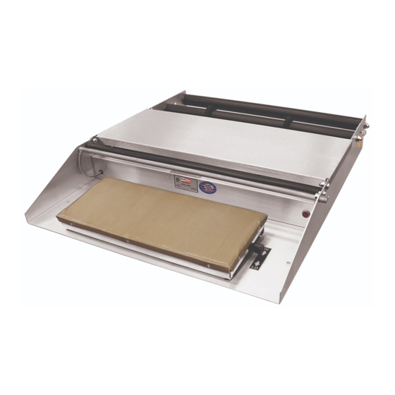
Model 625A
Model 600A
Model 825A
READ ALL INSTRUCTIONS CAREFULLY BEFORE OPERATING EQUIPMENT
TABLE TOP OVERWRAPPERS
AXLE MOUNT MODELS:
MODEL 625A
SINGLE ROLL WITH MOUNTING AXLES
MODEL 625A MINI
COMPACT SINGLE ROLL WITH MOUNTING AXLES
MODEL 825A
DUAL ROLL WITH MOUNTING AXLES
MODEL 875A
TRIPLE ROLL WITH MOUNTING AXLES
FILM ROLLER MODELS:
MODEL 600A
SINGLE ROLL WITH ROLLERS
MODEL 500A
COMPACT SINGLE ROLL WITH ROLLERS
MODEL 500A MINI
COMPACT SINGLE ROLL WITH ROLLERS
MODEL 800A
DUAL ROLL WITH ROLLERS
MODEL 850A
TRIPLE ROLL WITH ROLLERS
Revised 2013
Advertisement
Table of Contents

Related Manuals for Heat Seal 625A

Summary of Contents for Heat Seal 625A
- Page 1 OPERATING & SERVICE PARTS MANUAL TABLE TOP OVERWRAPPERS AXLE MOUNT MODELS: MODEL 625A SINGLE ROLL WITH MOUNTING AXLES MODEL 625A MINI COMPACT SINGLE ROLL WITH MOUNTING AXLES MODEL 825A Model 625A DUAL ROLL WITH MOUNTING AXLES MODEL 875A TRIPLE ROLL WITH MOUNTING AXLES...
- Page 2 Film Threading ....................... 3 Installing the Film Axle ....................4 625A Schematic & Parts List ..................5 625A Mini Schematic & Parts List ................6 825/875A Schematic & Parts List ................. 7 600A Schematic & Parts List ..................8 800/850A Schematic & Parts List ................. 9 Electrical Service Information ..................
- Page 3 FILM THREADING FOR AXLE TYPE WRAPPERS (625, 825, 875): See instructions on next pages to load the film onto the axle. Thread the film as shown, one at a time or as needed. FOR ROLLER TYPE WRAPPERS (600, 800, 850): Rest film Roll on top of two rollers, centering film between the film guides.
- Page 4 INSTALLING & ADJUSTING THE FILM AXLE INSTALLING COMPLETE AXLE ASSEMBLY (625-A) Position the complete axle assembly on the rear of the wrapper with the removable end cap (1) on the left side and INSTALLING THE AXLE the bearing blocks (2) on the outside of the sides of the Place the ends of axle into the grooves on lower bearing machine base (3) as shown in the drawing.
- Page 5 MODEL 625A REPLACEMENT PARTS ITEM PART # DESCRIPTION ITEM PART # DESCRIPTION 6110-023 Film Core Adapter Set 6305-048 Bearing Block Support Bracket 6305-018 Bearing Block Set 2135-001 Large Rubber Foot 3005-004 Film Core Axle, 21 15/16” L 1903-188 Hex Head Cap Screw...
- Page 6 MODEL 625A MINI REPLACEMENT PARTS ITEM PART # DESCRIPTION ITEM PART # DESCRIPTION 6110-023 Film Core Adapter Set 6305-048 Bearing Block Support Bracket 6305-018 Bearing Block Set 2135-001 Large Rubber Foot 3005-006 Film Core Axle, 16 7/8” L 1903-188 Hex Head Cap Screw...
- Page 7 MODEL 825A/875A REPLACEMENT PARTS ITEM PART # DESCRIPTION ITEM PART # DESCRIPTION 5901-011 Non-stick Cover, 6 by 15 6305-075 Bearing Block Set 3005-004 Film Core Axle, 21 15/16”L 5901-001 Non-stick Cover, 8 by 15 6310-046 Right Hand Side Plate 6101-020 Hot Plate Assy, 6 by 15 6310-047 Left Hand Side Plate...
- Page 8 MODEL 600A REPLACEMENT PARTS ITEM PART # DESCRIPTION ITEM PART # DESCRIPTION 6301-017 Film Roller Assembly 11 1927-008 Vinyl Wire Clamp 6301-018 Vinyl Film Retainer 12 1911-038 Clinch Nut 6301-019 Film Retainer Rod 13 1923-002 Thumb Screw 1958-001 Metal Shaft Retainer 14 1824-011 Cut-off Rod, 23”...
- Page 9 MODEL 500A REPLACEMENT PARTS ITEM PART # DESCRIPTION ITEM PART # DESCRIPTION 5901-011 Non-stick Cover, 6 By 15 10 6301-018 Vinyl Film Retainer 6101-020 Hot Plate Assy, 6 By 15 11 6102-052 Wrapping Bridge 1833-002 Fiber Insulator Washer 12 6301-020 Film Roller Brake 2150-232 Hot Plate Temp Control Decal...
- Page 10 MODEL 500A MINI REPLACEMENT PARTS ITEM PART # DESCRIPTION ITEM PART # DESCRIPTION 5901-014 Non-stick Cover, 6 By 9 10 6305-120 Vinyl Film Retainer 6305-132 Hot Plate Assy, 6 By 9 11 6305-065 Wrapping Bridge 1833-002 Fiber Insulator Washer 12 6301-020 Film Roller Brake 2150-232 Hot Plate Temp Control Decal...
- Page 11 MODEL 800A/850A REPLACEMENT PARTS ITEM PART # DESCRIPTION ITEM PART # DESCRIPTION 5901-011 Non-stick Cover, 6 by 15 1911-038 Clinch Nut 5901-001 Non-stick Cover, 8 by 15 6301-020 Film Tension Brake 6101-020 Hot Plate Assy, 6 by 15 3010-021 Film Retainer 6102-043 Hot Plate Assy, 8 by 15 6301-017...
- Page 12 ELECTRICAL SERVICE INFORMATION ELECTRICAL REQUIREMENTS All Models are 110 Volts, 10 Amps. HOT ROD CIRCUIT BOARD TEST A standard 115 volt neon circuit tester can be used for these tests. CHECKING FUSES Remove the fuse from their housing units located on the front of the electrical box. If a visual inspection does not verify a blown fuse check for continuity by using the meter to read across the two terminals of the fuse.
- Page 13 ELECTRICAL DIAGRAMS ITEM PART # DESCRIPTION 1821-013 Fuse Holder 1821-034 Fuse 1875-002 Terminal Block 1851-052 Power Cord 1872-008 Toggle Switch (Series A) 1872-009 Rocker Switch for 500 Series 1836-004 Pilot Light 1824-011 Cut-Off Hot Rod, 23” L 6110-016 Element 1818-001 Circuit Board 1881-002 Thermostat...
- Page 14 ELECTRICAL BOX & HOT PLATE PARTS TO SERVICE ELECTRICAL PARTS ON ELECTRICAL BOX: Lift up the wrapping bridge, then remove the screws holding the electrical control housing to the base. Lift out and replace parts. ELECTRICAL BOX REPLACEMENT PARTS ITEM PART # DESCRIPTION Standard Size Unit Shown 1818-001...
Need help?
Do you have a question about the 625A and is the answer not in the manual?
Questions and answers