Table of Contents
Advertisement
Quick Links
Advertisement
Table of Contents

Related Manuals for QSC Q-SYS


Summary of Contents for QSC Q-SYS
- Page 1 ™ Hardware User Guide I/O-8 Flex – Channel Expander TD-000520-00-A *TD-000520-00*...
-
Page 2: Important Safety Instructions
EXPLANATION OF TERMS AND SYMBOLS The term “WARNING!” indicates instructions regarding personal safety. If the instructions are not followed the result may be bodily injury or death. The term “CAUTION!” indicates instructions regarding possible damage to physical equipment. If these instructions are not followed, it may result in damage to the equipment that may not be covered under the warranty. -
Page 3: Fcc Statement
IMPORTANT!!: The Q-SYS I/O-8 Flex may operate at elevated temperatures and therefore its exterior may become noticeably warm. This is normal. The Q-SYS I/O-8 Flex is designed with convection cooling in mind and therefore incorporates industrial high-temp components to accommodate higher operating temperatures. -
Page 4: Rohs Statement
The QSC Q-SYS I/O-8 Flex is in compliance with European Directive 2011/65/EU – Restriction of Hazardous Substances (RoHS2). The QSC Q-SYS I/O-8 Flex is in compliance with “China RoHS” directives. The following chart is provided for product use in China and its territories: QSC Q-SYS I/O-8 Flex 部件名称... -
Page 5: What's In The Box
Joining Plate (1x) (6x) (6x) (4x) Rack-Ear Cover Phillips Pan Head Phillips Flathead Foam Spacer Label M4 x 7 mm M3 x 6 mm (8x) (2x) Flex Channels External Power RS232 Tx/Rx GPIO (black) (blue) (green) (green) QSC Warranty Saftey and TD-000453 Regulatory Statments TD-001514 TD-000520-00-A... -
Page 6: Installation
Installation Ventilation • Recommend 1RU (1.75 in / 44.45 mm) space above I/O-8 Flex. • Minimum open space of 6 inches measured from back of I/O-8 Flex. NOTE!: In order to provide adequate dissipation of heat, keep the space directly above and to the rear of the I/O-8 Flex free of obstacles. - Page 7 A. One I/O-8 Flex 19-inch Rack (Left or Right Mount) Top Side Top Side Front Panel Front Panel B. Two I/O-8 Flex's 19-inch Rack (Front or Rear Facing Out) Bottom Side Amp 2 Front Panel Bottom Side Amp 1 Front Panel Bottom Side Amp 2 Rear Panel Bottom Side...
- Page 8 Front or Rear Facing Out C. One I/O-8 Flex Half Rack ( 1. (1) Top Side Front Panel 2. (2) 3. (6) Top Side Rear Panel D. Under Table or on Wall Mounting Surface Not supplied – use appropriate screws for mounting surface.
-
Page 9: Rack Mounting Options
E. Free-Standing on Desk/Table Bottom Side Front Panel Rack Mounting Options All Configurations Using the examples shown in mounting options A through E, you can mount any of the I/O-8 Flex configurations. The example at the lower right can be flipped to accommodate a single I/O-8 Flex on the left side. -
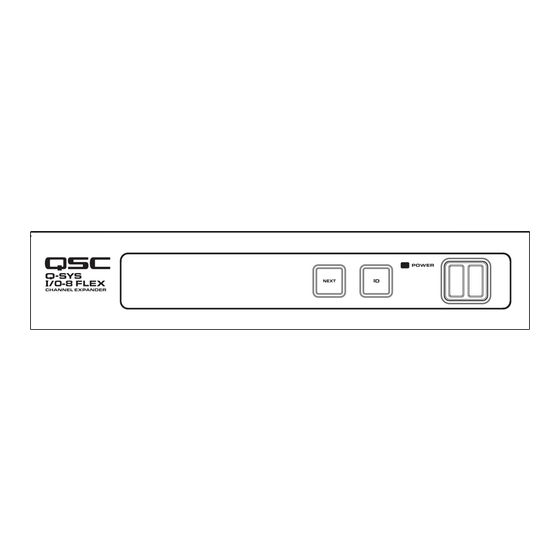
Page 10: Front Panel
4. Earth Ground – The ground connection uses the farthest right pins (not numbered) for both GPIO INPUTS and GPIO OUTPUTS 5. GPIO INPUTS – 8 inputs, 0-24V analog input or contact closure (pins labeled 1-8 equal pins 1-8 in the Q-SYS Designer GPIO Input component) 6. -
Page 11: Input/Output Connectors
Input / Output Connectors Balanced Unbalanced 3-Pin, color-coded, Euro Connectors • Flex Channels (8 blue) CAUTION!!: A single channel consists of three pins. It is possible to plug in a connector that straddles two channels. Be sure that the plugs do not straddle two channels. - Page 12 Front Panel OLED Screens DESIGN STATUS Design Status <Device Name> DEVICE: • Device – The name of the I/O-8 Flex as defined in Q-SYS Designer. <Design Name> DESIGN: • Design – The name of the currently running design. <Status> STATUS: •...
- Page 13 Flex In Channel Status Flex In NOTE!: If a Flex channel is set to Input, there is Mute no information shown under the same channel on the Flex Out screen. If the Flex channel is set to Clip Output, there is no information for that channel on Signal the Flex In screen.
- Page 14 Dimensions 240mm 9.43 in. 220mm 8.66 in. 44mm 1.75 in. TD-000520-00-A...
- Page 15 Q-SYS I/O-8 Flex Channel Expander Specifications Inputs/Outputs Audio Flex Channel Capacity Audio Flex Channel Assignments Each channel can be configured as a mic/line input or as a line output (configured through Q-SYS Designer software) Rear Panel Indicators "Link", "Speed", and "Activity" LEDs on all LAN ports...
-
Page 16: Controls And Indicators
Q-SYS I/O-8 Flex Channel Expander Specifications Controls and Indicators Front Panel Controls "NEXT" OLED page forward capacitive touch button "ID" device identification capacitive touch button "Clear Network Settings" invoked when "NEXT" and "ID" are pressed simultaneously Front Panel Conenctors AUX USB: USB Host x 2 (Type A connectors) Front Panel Indicators Blue "POWER"... -
Page 17: Mailing Address
FAX: +1 (714) 754-6173 © 2017 QSC, LLC. All rights reserved. QSC and the QSC logo are registered trademarks of QSC, LLC in the U.S. Patent and Trademark office and other countries. Q-SYS, Q-LAN and, Q-SYS Designer are trademarks of QSC, LLC. Patents may apply or be pending.
Need help?
Do you have a question about the Q-SYS and is the answer not in the manual?
Questions and answers