HP 1920 Series Getting Started Manual
Hide thumbs
Also See for 1920 Series:
- User manual (547 pages) ,
- Getting started manual (10 pages) ,
- Supplementary manual (63 pages)

Related Manuals for HP 1920 Series


Summary of Contents for HP 1920 Series
-
Page 1: Getting Started Guide
HP 1920 Gigabit Ethernet Switch Series Getting Started Guide 5998-7148 Part number: 5998-7148 Document version: 6W102-20141224... - Page 2 The only warranties for HP products and services are set forth in the express warranty statements accompanying such products and services. Nothing herein should be construed as constituting an additional warranty.
-
Page 3: Table Of Contents
Verification before power-on ······························································································································· 14 Powering on the switch ········································································································································· 14 Support and other resources ····································································································································· 16 Contacting HP ································································································································································ 16 Subscription service ·············································································································································· 16 Related information ························································································································································ 16 Documents ······························································································································································ 16 ... - Page 4 Environmental specifications ········································································································································· 24 Power specifications ······················································································································································ 24 AC input voltage specifications ··························································································································· 24 RPS DC input voltage specifications and RPS compatibility ············································································· 25 Power consumption specifications for non-PoE switches ··················································································· 25 Power consumption specifications for PoE switches ·························································································· 25 ...
-
Page 5: Preparing For Installation
IMPORTANT: For regulatory identification purposes, the switches are assigned Regulatory Model Numbers (RMNs). The RMNs should not be confused with the marketing name HP 1920, or the product codes. Safety recommendations To avoid any equipment damage or bodily injury, read the following safety recommendations before installation. -
Page 6: Examining The Installation Site
The accessories shipped with the switch, including but not limited to power cables, are intended • only for the switch. Please do not use them for other products. Examining the installation site The switches must be used indoors. You can mount your switch in a rack or on a workbench, but make sure: A minimum clearance of 5 cm (1.97 in) is reserved at the air inlet and exhaust vents for ventilation. -
Page 7: Emi
Maximum concentration (mg/m 0.05 0.01 All electromagnetic interference (EMI) sources, from outside or inside of the switch and application system, adversely affect the switch in the following ways: A conduction pattern of capacitance coupling. • Inductance coupling. • • Electromagnetic wave radiation. Common impedance (including the grounding system) coupling. -
Page 8: Installing The Switch
WARNING! Before installing or moving the switch, remove the power cord. You can install an HP 1920 switch in a 19-inch rack, on a workbench, or on a wall. Mounting the switch in a 19-inch rack by using mounting brackets Wear an ESD wrist strap and make sure it makes good skin contact and is reliably grounded. - Page 9 Figure 3 Attaching Type-C mounting brackets to the switch Place the switch on a rack shelf in the rack. Push the switch in until the oval holes in the brackets align with the mounting holes in the rack posts. Attach the mounting brackets to the rack posts with screws. Figure 4 Attaching Type-A mounting brackets to the rack post...
- Page 10 Figure 5 Attaching Type-B mounting brackets to the rack post Figure 6 Attaching Type-C mounting brackets to the rack post...
-
Page 11: Mounting The Switch On A Workbench
Mounting the switch on a wall Only the HP 1920-8G switch can be installed on a wall. The type of screws used to mount the switch on the wall depends on the wall type. This section uses a concrete wall as an example. - Page 12 Figure 9 Hole spacing Insert one wall anchor into each hole until the anchors are flush with the wall surface. Drive one screw into each wall anchor, and tighten the screws just enough to keep it secure in the wall anchor. Leave a minimum clearance of 1.5 mm (0.06 in) between the base of the screw head and the wall anchor so the switch can hang on the screws securely.
-
Page 13: Connecting Cables
Connecting cables Connecting network cable Use crossover cable or straight through cable to connect a PC or other network devices to the Ethernet port of the switch. Figure 12 Connecting network cable Installing the SFP transceiver module and optical fibers CAUTION: Hold the SFP transceiver module by its two sides when you install or remove the module. -
Page 14: Connecting The Console Cable
Figure 13 Installing the SFP transceiver module and optical fibers Connecting the console cable To connect a terminal (for example, a PC) to the switch: Wear an ESD wrist strap and make sure it makes good skin contact and is reliably grounded. Connect the DB-9 female connector of the console cable to the serial port of the PC. -
Page 15: Connecting The Dc Power Cord
Make sure the DC power cord is shorter than 3 m (9.84 ft). The HP 1920-24G-PoE+ (370W) and HP 1920-48G-PoE+ (370W) support DC RPS power. If only the DC power cord is connected, the switch operates correctly when the DC input voltage is in the range of –47 VDC to –57 VDC. -
Page 16: Verifying The Installation
Figure 16 Connecting the DC power cord to the DC power receptacle Verifying the installation After you complete the installation, verify the following items: There is enough space for heat dissipation around the switch. • • The rack or workbench is stable. The grounding cable is securely connected. -
Page 17: Accessing The Switch For The First Time
Accessing the switch for the first time Setting up the configuration environment The first time you access the switch you must use a console cable to connect a console terminal, for example, a PC, to the console port on the switch. Figure 17 Connecting the console port to a terminal Connecting the console cable Console cable... -
Page 18: Connection Procedure
The terminal (for example, a PC) has started, and its configuration parameters have been correctly • set. Powering on the switch Power on the switch (for example, an HP 1920-24G switch), and the following information is displayed: Starting..**************************************************************************** HP 1920-24G Switch JG924A BootWare, Version 1.09... - Page 19 ........................................................................................Done! System application is starting... User interface aux0 is available. Press ENTER to get started. Press Enter and the system displays the following prompt: <Hp> This prompt indicates that the switch is ready to configure.
-
Page 20: Support And Other Resources
Related information Documents To find related documents, browse to the Manuals page of the HP Business Support Center website: http://www.hp.com/support/manuals For related documentation, navigate to the Networking section, and select a networking category. •... -
Page 21: Conventions
Conventions This section describes the conventions used in this documentation set. Command conventions Convention Description Boldface Bold text represents commands and keywords that you enter literally as shown. Italic Italic text represents arguments that you replace with actual values. Square brackets enclose syntax choices (keywords or arguments) that are optional. Braces enclose a set of required syntax choices separated by vertical bars, from which { x | y | ... - Page 22 Network topology icons Represents a generic network device, such as a router, switch, or firewall. Represents a routing-capable device, such as a router or Layer 3 switch. Represents a generic switch, such as a Layer 2 or Layer 3 switch, or a router that supports Layer 2 forwarding and other Layer 2 features.
-
Page 23: Appendix A Chassis Views And Technical Specifications
Appendix A Chassis views and technical specifications Chassis views 1920-8G Figure 19 1920-8G front panel (1) 10/100/1000BASE-T copper ports (2) 100/1000BASE-X SFP fiber ports (3) Console port (4) Fiber port LEDs (5) Copper port LEDs (6) Power LED Figure 20 1920-8G rear panel (1) Grounding screw (2) AC power receptacle (3) Security slot... -
Page 24: 1920-24G
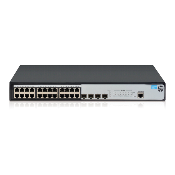
Figure 22 1920-16G rear panel (1) Grounding screw (2) AC power receptacle 1920-24G Figure 23 1920-24G front panel (1) 10/100/1000BASE-T copper ports (2) 100/1000BASE-X SFP fiber ports (3) Fiber port LEDs (4) Copper port LEDs (5) Power LED (6) Console port Figure 24 1920-24G rear panel (1) Grounding screw (2) AC power receptacle... -
Page 25: 1920-8G-Poe+ (65W)
Figure 26 1920-48G rear panel (1) Grounding screw (2) AC power receptacle 1920-8G-PoE+ (65W) Figure 27 1920-8G-PoE+ (65W) front panel (1) 10/100/1000BASE-T copper ports (2) 100/1000BASE-X SFP fiber ports (3) Console port (4) Fiber port LEDs (5) Copper port LEDs (6) Power LED Figure 28 1920-8G-PoE+ (65W) rear panel (1) AC power receptacle... -
Page 26: 1920-24G-Poe+ (180W)
Figure 30 1920-8G-PoE+ (180W) rear panel (1) AC power receptacle (2) Grounding screw (3) Security slot 1920-24G-PoE+ (180W) Figure 31 1920-24G-PoE+ (180W) front panel (1) 10/100/1000BASE-T copper ports (2) 100/1000BASE-X SFP fiber ports (3) Fiber port LEDs (4) Copper port LEDs (5) Power LED (6) Console port Figure 32 1920-24G-PoE+ (180W) rear panel... -
Page 27: 1920-48G-Poe+ (370W)
Figure 34 1920-24G-PoE+ (370W) rear panel (1) Grounding screw (2) AC power receptacle (3) DC power receptacle 1920-48G-PoE+ (370W) Figure 35 1920-48G-PoE+ (370W) front panel (1) Copper port LED switching button (2) Copper port mode LED (3) RPS power LED (4) Power LED (5) Console port (6) 100/1000BASE-X SFP fiber ports... -
Page 28: Ports And Interface Card Slots
Chassis Dimensions (H x W x D) Maximum weight 1920-24G 44 x 440 x 173 mm (1.73 x 17.32 x 6.81 in) 2.2 kg (4.85 lb) 1920-8G-PoE+ (65W) 44 x 330 x 230 mm (1.73 x 12.99 x 9.06 in) 2.1 kg (4.63 lb) 1920-8G-PoE+ (180W) 44 x 330 x 230 mm (1.73 x 12.99 x 9.06 in) -
Page 29: Rps Dc Input Voltage Specifications And Rps Compatibility
RPS DC input voltage specifications and RPS compatibility Chassis RPS input rated voltage range 1920-24G-PoE+ (370W) –54 VDC to –57 VDC 1920-48G-PoE+ (370W) –54 VDC to –57 VDC Power consumption specifications for non-PoE switches Chassis Minimum power consumption Maximum power consumption 1920-8G 8.5 W 1920-16G... -
Page 30: Cooling System
Cooling system Chassis Fixed fans 1920-8G 1920-8G-PoE+ (65W) 1920-16G 1920-24G 1920-48G 1920-8G-PoE+ (180W) 1920-24G-PoE+ (180W) 1920-24G-PoE+ (370W) 1920-48G-PoE+ (370W) -
Page 31: Appendix B Leds
Appendix B LEDs Power LED Table 5 Power LED description Status Description Steady green The switch is powered on and the power supply is operating correctly. Flashing green The switch is powered on and is performing the self-test. The switch is not powered on or the power supply is faulty. Copper port LEDs Link/ACT LEDs Table 6 Link/ACT LED description... -
Page 32: Rps Led
No RPS is used or the RPS is supplying power incorrectly. Copper port mode LED The HP 1920-48G-PoE+ (370W) uses the copper port mode LED to indicate the mode of copper port LEDs. You can use the copper port LED switching button to change the mode of copper port LEDs. -
Page 33: Appendix C Troubleshooting
Appendix C Troubleshooting Table 1 1 describes the troubleshooting methods for common issues that you might encounter while using and managing the switch. If a problem persists, contact HP Support. Table 11 Troubleshooting methods Symptom Troubleshooting method Verify that the correct power source is used and the power cords are correctly connected.
Need help?
Do you have a question about the 1920 Series and is the answer not in the manual?
Questions and answers