Table of Contents
Advertisement
Advertisement
Table of Contents

Related Manuals for moyno 2000


Summary of Contents for moyno 2000
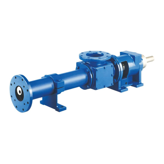
- Page 1 SERVICE MANUAL ® MOYNO 2000 Pumps G1 Flanged Models...
-
Page 2: Table Of Contents
Note: This service manual outlines installation, operation and maintenance procedures for the flanged “G1” models of the Moyno 2000 pump. For information on the open throat (G2) and/or the bridge breaker (G3) models of the Moyno 2000 pump, refer to the G2/G3 Service Manual, or contact your nearest Moyno pump representative. -
Page 3: Introduction
G1 Flanged Models 1-1. INTRODUCTION 1-2. GENERAL The Moyno® 2000 Pump is the culmination of over 70 years of experience in manufacturing and marketing fluids handling equipment. This rugged pump has been engineered to be the most reliable product ever sold under the Moyno name. -
Page 4: Trim Code
2-3. PIPING Standard stator materials used in the Moyno 2000 pump are as follows: 2-4. Suction piping should be as short as possible. Nor- mally, the suction line should be the same size as the pump B —... -
Page 5: Foundation
Complete base If a mechanical seal is used, consult the seal manufac- mounted units supplied by Moyno including pump and driver turers’ instructions for seal flush requirements. are leveled with respect to the base at the factory. Shifting may occur during shipment. -
Page 6: Operation
Page 4 4-2. GENERAL 3-1. OPERATION The Moyno 2000 pump has been designed for a minimum 3-2. INITIAL CHECK of maintenance, the extent of which is routine adjustment and lubrication of packing. The pump is one of the easiest Before putting the pump into operation, the following... -
Page 7: Packing Replacement
Page 5 4-4. PACKING REPLACEMENT 2. Shut off pump. When leakage can no longer be regulated by tightening 3. Close suction and discharge valves. the gland nuts, remove and replace the packing. Replace as follows: 4. Turn off flush water to packing or mechanical seal, if used. -
Page 8: Drive End Gear Joint Removal
Method 1: Utilize Moyno’s Hydraulic Stator Removal Device gear joint seal (13) should be replaced. (SRD). See separate SRD service manual or contact the local Moyno distributor for further information on this new 4-14. Drive Shaft and Bearings Removal product. -
Page 9: Inspection
The base surface metal is not pitted or corroded. 4-20. Packing. It is sound practice to always replace pack- 4. Rotors may be sent to Moyno or any other competent ing (22) whenever the pump bearing housing is plating shop. Rotors should be stripped and replated to disassembled. -
Page 10: Packing Installation
Page 8 4-28. Bearing/Drive Shaft Assembly 4. Approved lubricants: 1. Bearings must be pressed on the shaft in the following CAUTION: Do not mix different brands of lubricants for sequence: [Larger units (G drive end and larger) require the same application. heating of the bearings to 250°... -
Page 11: Rotor/Stator Assembly
8.75 Moyno’s Hydraulic Stator Removal Device 2G065G1, 2G098EG1 6.06 3K345G1 8.75 (SRD). See separate SRD service manual or contact the local Moyno distributor for further 1G090G1 6.06 1K620G1 8.75 information on this new product. 2G090G1 6.06 2K620G1 8.75 1G115G1 6.19 1K800G1 7.50... -
Page 12: Rotor/Stator To Drive End Assembly
Page 10 Figure 4-6. Rotor Thrust Plate Seating Detail 5. Apply a film of grease to the splines on the inside of the gear balI (10). Install gear ball on connecting rod (38), with counter-bored end (end without splines) first on connecting rod. -
Page 13: Stator Support/Discharge Assembly
Page 11 5. If the stator is firmly seated against stator gasket in 11. Thread the six socket head screws (E) through the suction housing recess, and connecting rod extends beyond drive shaft head into the drive shaft. Tighten them evenly face of drive shaft by specified amount, stator may be se- until face of drive shaft head is tight against face of drive cured to suction housing. -
Page 14: Packing Specification
A — Standard size with chrome plating 4-39. PACKING SPECIFICATION B — Non-plated (no plating) C — Standard undersize Standard packing on all Moyno 2000 pumps consists of E — Standard oversize braided PTFE fibers impregnated with ultra-fine graphite. G — Ceramic coating Optional types of packing are available for food, high K —... -
Page 15: Standard Hardware
Page 13 4-43. STANDARD HARDWARE J 0 6 5 G 1 , J 0 9 0 G 1 J 1 1 5 G 1 , J 1 7 5 G 1 , J 3 3 5 G 1 , J 2 2 0 3/4-10 X 4-1/2 J 2 2 0 3/4-10 X 2... -
Page 16: Selecting The Correct Part
Page 14 4-44. SELECTING THE CORRECT PART FOR YOUR MOYNO 2000 PROGRESSING CAVITY PUMP PUMP MODEL DESIGNATION Table 4-1 Basic Drive End Parts: Select Reference Number part by Drive End (1G065G1 CDQ AAA) and (Page 15) Type Designation (1G065G1 CDQ AAA) where listed. -
Page 17: Parts List
Page 15 4-45. PARTS LIST Table 4-1. Parts List DRIVE END SIZE REF. DESCRIPTION Radial Grease Seal ........ AG0611 PF0611 PG0611 PH0611 PJ0611 PK0611 Bearing Cover Plate ....... PE0341 PF0341 PG0341 PH0341 PJ0341 PK0341 O-Ring ............ PE110Q BJ112Q BK113Q PH110Q BH114Q PK110Q Drive Shaft Head ........ - Page 18 Page 16 4-45. PARTS LIST (Cont.) Table 4-1. Parts List (Cont.) DRIVE END SIZE REF. DESCRIPTION Stator Ring Clip–See Table 4-6 Stator Clamp Ring–See Table 4-6 Discharge Flange–See Table 4-8 Connecting Rod–See Table 4-7 Gear Joint Shell: CDQ, CDR, CDB, CDF ....... PE0911 PF0911 PG0911...
- Page 19 Page 17 Table 4-3. Parts List —Type Designation Begins with SS REF. NO: ADAPTOR STATOR SUCTION STATOR RETAINING MODEL BUSHING ADAPTOR HOUSING SUPPORT RING (2) E008 ----- ----- PE0026 BE0381 AE0085 E012, E018E ----- ----- PE0026 BE0381 AE0085 E022, E033E ----- ----- PE0027...
- Page 20 Page 18 Table 4-5. Stator Gasket (Ref. No. 34) Part Number TYPE DESIGNATION CDQ, CSQ, SSQ, MODEL CDR,CSR, SSR CDF, CSF, SSF CDB, CSB, SSB E008, E012, E018E, F012 BE085Q BE085F BE085B E022, E033E, F022, G022 BF085Q BF085F BF085B E036, F036, F054E, G036, H036 BG085Q BG085F BG085B...
- Page 21 Page 19 Table 4-7. Connecting Rod (Ref. No. 38) Part Number TYPE DESIGNATION CDQ, CDR, CSQ, CSR, CSB, CSF, MODEL CDB, CDF SSQ, SSR, SSB, SSF E008, E012, E018E, E022, E033E PE0251 PE0256 E036 PE0252 PE0257 F012, F022, F033E, F036, F050, F054E, F075E PF0251 PF0256 F065...
- Page 22 Page 20 Table 4-9. Discharge Flange (Ref. No. 37) for Type Designations Beginning with CS or SS STAGES MODEL 1, 2, AND 3 E008, E012, E018E 6E0126 BE0127 BE0127 ----- E022, E033E BF0126 BF0126 ----- ----- E036, E050 BG0126 ----- ----- ----- F012...
- Page 23 Page 21 Table 4-11. Rotor (Ref. No. 40) for Type Designations Beginning with CS or SS STAGES MODEL E008 C81E81 C82E81 ----- C84E81 C86E81 ----- E012 C81EE1 C82EE1 ----- C84EE1 C86EE1 ----- E018E E81E181 E82E181 ----- ----- ----- ----- E022 C81EF1 C82EF1 -----...
- Page 24 Page 22 SEE PG. 23 FOR EXPLODED VIEW OF PUMP Table 4-13. Shaft Sleeve Arrangement REF. NO: SHAFT SLEEVE KIT* PACKING LANTERN PACKING SUCTION RING HALF GLAND HOUSING HALF CDO,CSR CDR, SSQ CSB CSQ, SSR MODELS MODELS MODEL E008, E012, E018E KE003Q KE003B KE003F...
- Page 25 Page 23 Figure 4-8. Pump Exploded View...
-
Page 26: Shaft Sleeve Arrangement
Page 24 Figure 4.9. Shaft Sleeve Arrangement Figure 4-9. Shaft Sleeve Arrangement 4-46. SHAFT SLEEVE ARRANGEMENT Some pumps have a sleeve installed on the drive shaft to receive any possible wear caused by the packing. See sleeve kit (43, fig. 4-9), and the cross section illustration (fig. 4-10). - Page 27 Page 25 Figure 4-11. Stuffing Box. Dimensions with shaft sleeve (inches) Drive + .000 +.005 ± .03 + .05 B.C. Shaft Size - .003 - .00 - .00 O.D. 5.500 3.750 2.81 4.19 4.37 2.750 6.589 4.250 3.31 4.44 5.00 3.250 7.498 5.000...
-
Page 28: Fiber Deflector Option
The Moyno Fiber Deflector is designed to prevent an accu- mulation of rags and stringy material around the connecting rod and rotor head area of your Moyno 2000 pump. The Fiber Deflector eliminates the potential for equipment damage and downtime due to blockage. -
Page 29: Operation
Page 27 6. Wipe a small amount of grease in the groove of the Having determined best alternative your application, install all hardware, leaving the flush gland drain flush gland halves. unconnected for now. Packing gland nuts should be evenly 7. -
Page 30: Standard Hardware
Page 28 4-57. STANDARD HARDWARE Drive End Ref. Description Oty. Hex Head Screw ¼-20 x 2” Lg ¼-20 x 2” Lg -18 x 2¼” Lg -16 x 2 ¾” Lg -16 x 2¼” Lg ½-13 x 3¼” Lg Note: All screws are 18-8 stainless steel. *Note: Lip seal is cutaway for illustrative purposes. -
Page 31: Troubleshooting Chart
Page 29 4-59. TROUBLESHOOTING CHART © 2001 by Moyno, Inc. ® Moyno is a registered trademark of Moyno, Inc. Moyno, Inc. is a Unit of Robbins & Myers, Inc. - Page 32 U.S.A. Thank you for choosing a Moyno Pump. Please take the time to complete this warranty registration form.Upon receipt of your form, your standard limited warranty on defective material and workmanship will be extended to twice the standard period of time at no additional cost to you. We appreciate your business and look forward to serving you in the future.
Need help?
Do you have a question about the 2000 and is the answer not in the manual?
Questions and answers