Table of Contents
Advertisement
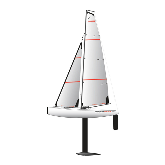
650mm R/C High Performance Racing Sailboat
For more information about the boat
and the DragonForce 65 racing class. visit:
www.dfracing.world
Specification
• Length: 650mm
• Beam: 116.5mm
• Rig Height: 915mm
• Overall height: 1338mm
• RTR total weight: 1200g (Batteries not included)
• Sail area (Mainsail): 1460cm²
• Sail area (Jib): 766cm²
• Sail area (overall): 2226cm²
• Hull material: Moulded ABS with painted finish with logo stickers
• Supplied in two versions: RTR version (8815) with transmitter & receiver
ARTR version (8815A) with no radio gear
• RTR version requires 4pcs AA battery for transmitter & 4pcs AA battery for receiver
Advertisement
Table of Contents

Related Manuals for Joysway DRAGONFORCE 65


Summary of Contents for Joysway DRAGONFORCE 65
- Page 1 650mm R/C High Performance Racing Sailboat For more information about the boat and the DragonForce 65 racing class. visit: www.dfracing.world Specification • Length: 650mm • Beam: 116.5mm • Rig Height: 915mm • Overall height: 1338mm • RTR total weight: 1200g (Batteries not included) •...
- Page 2 INSTRUCTION MANUAL THIS MODEL IS NOT A TOY. THESE INSTRUCTIONS SHOULD BE READ BY A SUPERVISING ADULT DRAGONFORCE 65 2.4GHz R/C RACING SAILBOAT This Instruction Manual covers models 8815(RTR) & 8815A(ARTR) IMPORTANT: This is not a toy. Assembly and operating of this boat requires adult supervision.
- Page 3 BASIC BOAT TERMINOLOGY The front of the boat. STERN The back of the boat. PORT This is the left side of the boat when viewed from the Stern. STARBOARD This is the right side of the boat when viewed from the Stern. HULL The body of the boat.
- Page 4 DISPLAY STAND ASSEMBLY 1 Identify all stand components from box. Note: The nuts, bolts and EVA foam support pads are located in the fittings pack. 2 Bolt the plastic moulded components together with the twelve nut & bolts supplied. 3 Construct the leg sections. Note: The leg sections are the four longer tubes. 4 Fit the three stretcher tubes.
- Page 5 RUDDER ASSEMBLY 1 Identify all Rudder components from the box. Note: The metal Rudder Arm is located in the fittings pack. 2 Insert Rudder into Hull. 3 Ensure the Rudder is pushed fully up into the Hull, then, pushing the Rudder Arm down, tighten the grub screw. This will locate on the flat section of the metal Rudder Shaft.
- Page 6 3 Fit the wire Mainsail Luff Rings to all five eyelets down the Mainsail Luff (front edge). Leave the rings open at this stage. 4 Slide the Mast Stub into the base of the Long Mast section, taking care that the bevelled edge of the plastic collar is facing downwards. A spot of CA glue on the upper section of the Mast Stub before assembly will hold these two parts together for a permanent fix.
- Page 7 I N S T R U C T I O N M A N U A L...
- Page 8 JIB BOOM SETUP Silicone Rings A & B Counterweight Jib Clew Hook Rubber O Ring Silicone Ring Jib Tack Hook Jibsheet Guide Eye Jibsheet Guide Eye 63mm 160mm 1 Set the rear Jibsheet Guide Eye and Silicone Rings A & B to the positions shown above. The positions of the other silicone rings and sail clew hook are adjustable to facilitate correct sail trim.
- Page 9 12 Thread the Dyneema cord coming from the rear end of the JibBoom through the first two eyes of a Bowsie, then up through the 6mm ring at the lower end of the Topping Lift and back through the final hole in the Bowsie. With the Bowsie positioned approximately 40mm below the ring, tie off the cord and trim off the loose end.
- Page 10 I N S T R U C T I O N M A N U A L...
- Page 11 POWERING UP THE BOAT If you’ve bought the ‘Ready To Race’ version (8815) of the boat you will have the Joysway Transmitter and Receiver. The transmitter (Tx) and Receiver (Rx) will already be ‘bound’ and full operating instructions for this radio set are supplied.
- Page 12 SHEETING SETUP 1 For initial sheet setup of both the Jib and Mainsheet, pull the winchline in to its close-hauled (sheeted fully in) position and don’t move it until both sheets are fully installed. 2 Cut a 500mm length of Dyneema for the Mainsheet. Tie a loop in one end and clip it in to the Winch Line Clip(A) (see photo 2), run it forward and through the metal ring on the Mainsheet Bridle(B), up through the Mainsheet Guide(C) on the Main Boom, back along the boom through the first two Holes in Bowsie(D), through the Rubber O Ring(E), through the Mainsheet Guide(F), forward through the Rubber O Ring(E) again and then through the final hole in the Bowsie(D).
- Page 13 Sheeted Out: The Mainboom should sheet out to around 80º to the Hull’s centreline Sheeted Out: The Jib Boom should sheet out to around 85º to the Hull’s centreline Sheeted In: The end of the Jib Boom should be just inside the inner edge Sheeted In: The end of the of the Gunwhale Mainboom should be over the...
- Page 14 Rudder: In center position IMPORTANT NOTICE Only sail your DragonForce 65 in still bodies of water. Never sail it in running water such as rivers or tidal waters. If you loose control of the boat you could loose it forever! Never attempt to swim after a stalled or stuck boat.
- Page 15 MAINTENANCE SPARE PARTS LIST If properly rigged and maintained the DragonForce65 will Item No Item Name be a very ‘dry’ boat. This is a very good thing as water and 880502 Standard keel with screws electrics are not the best of friends! 880503 Rudder There are some essential steps you need to take to keep...
- Page 16 This product complies with the essential requirements of all relevant EU Directives. A copy of the Declaration of Conformity can be obtained from the following website www.joysway-hobby.com For more information about the boat and the DragonForce 65 Racing Class please visit www.dfracing.world...
Need help?
Do you have a question about the DRAGONFORCE 65 and is the answer not in the manual?
Questions and answers