
Related Manuals for Vectronix BT PLRF25C


Summary of Contents for Vectronix BT PLRF25C
- Page 1 PLRF25C / PLRF25C BT User Manual Pocket Laser Range Finder with Compass English, Version 1.2 II 2013...
- Page 2 General Information Short Description PLRF25C / PLRF25C BT The PLRF25C is a ruggedized, pocket size, handheld, one button operated laser range- finder with integrated digital magnetic compass, sighting optic and data interface. The PLRF25C is capable to provide distance, azimuth and inclination information. The version PLRF25C BT is additonally equipped with integrated Bluetooth functionality.
- Page 3 For safe use of the device, please note the safety directions included in the User Manual. © 2013 Vectronix AG, ® All rights reserved. Warning Use of controls or adjustments or performance of procedures other than those specified herein may result in hazardous laser light exposure. Do not open the device housing or attempt your own repairs.
-
Page 4: Table Of Contents
Contents Safety Notices ............7 Care and cleaning . - Page 5 Complete measurement with data transfer (slope distance, horizontal and vertical distance, azimuth, inclination) .....26 Multiple object measurement ........27 Distance between two objects .
- Page 6 Built-In-Test ............40 Set Default Settings .
-
Page 7: Safety Notices
Safety Notices Laser Safety: Class 1 Important! according to IEC60825-1 Ed 2.0 (2007-03) Keep the instructions always in direct access for user and any personnel working at the instrument. Intended purpose The device • is designed as a handheld observation and surveying aid;... - Page 8 • Changes and modifications to the device the risk of by the customer. • injuries; • Use of accessories not expressly • instrument errors; approved by Vectronix AG. • damage to property; • Working in explosive enviroment or • malfunction; underground. Safety Notices...
- Page 9 • Observe the permissible storage temper- atures. Obligation of the Operator • Do not expose the device to strong The person responsible for the product mechanical shocks or abrupt tempera- must ensure that ture transitions during transport (moisture • the operators are qualified according to condensation).
- Page 10 Blinding hazard Physical injury hazard • Do not look into powerful light sources • Do not place the device on a vehicle with the device. parcel-shelf or dashboard – risk of injury when braking. • Do not open the device. The built-in laser can cause eye injuries.
-
Page 11: Care And Cleaning
Care and cleaning The devices performance The device does not need Lens cleaning and serviceability are condi- special care or cleansers. Particles of dirt should be tional on regular care and blown off or removed using immediate attention to Therefore a soft brush. - Page 12 Cleaning the casing Cleaning the interface cable Wipe the casing with a damp cloth. Pay special Protect the cable from damp attention to dirt and grease and dirt as much as around the button. possible! Wipe the cable Blow out the device with a damp cloth.
-
Page 13: Technical Data
Technical Data Optics Observation monocular Magnification Objective diameter 30 mm Field of view 6° / 106 mil Focus fixed (50m to infinity) Dioptric setting +4dpt to -4dpt PLRF25C-1.2en Technical Data... - Page 14 Magnetic Compass (azimuth and inclination) Azimuth units 360° / 6400mil / 6300mil / 6000mil Accuracy (1σ) Azimuth ± 10mil / ±0.6° Inclination angle ± 3mil / ±0.2° Display resolution 1° / 1 mil Max. inclination and bank angle ±45° Compass calibration menu driven Declination Array (adjustable)
- Page 15 Rangefinder Laser type 1550 nm Eye safety Class 1 Standard IEC60825-1 Ed 2.0 (2007-03) Range Performance 5m to >4000m Specified Performance 2500m* Accuracy (1σ) ±2 m (>50m to <1500m) ±5 m (<50m / >1500m) Display Resolution 1m / 1ft / 1yd * at visibility 15km, 2.3 x 2.3m target size, albedo 0.4, detection probability >90% PLRF25C-1.2en Technical Data...
- Page 16 Miscellaneous Power supply 1x 3V lithium battery, type CR123A Battery capacity (20°C) > 3000 measurements Immersion standard 1m, 30min 10m, 30min optional Operational temperature range -35°C to +63°C / -31°F to +145°F Storage temperature range (without battery) -40°C to +85°C / -40°F to +185°F Weight with battery and rubber cover 500g / 1.1lbs Dimensions with rubber cover...
-
Page 17: Getting Started
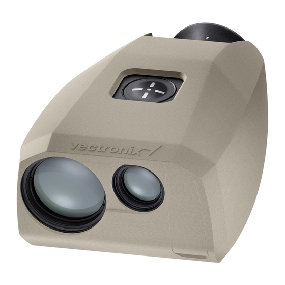
Getting started Instrument Overview Rubber Cover Push Button Eyecup Objective – Day Optics Objective – Transmitter Interface Protection Cap Interface Connector (5-Pin LEMO) Battery, CR123A Battery Case Cover Tripod Mount (1/4 inch) Type label (Name, Part Number, Serial Number) PLRF25C-1.2en Getting started... -
Page 18: Changing The Battery
Changing the battery Open the battery compartment. Insert one lithium battery type CR123 with +(positive) pole facing to the objectives. Close the battery cover. The device monitors the condition of the batteries. If the display shows , this indicates that the battery is BATT LOW almost used up. -
Page 19: Diopter Adjustment
Diopter adjustment Focus on an object farther than 100 m away and rotate the eyepiece to obtain a sharp image. Standard setting: 0 diopter If the device is being used by different people, remember your personal diopter setting. PLRF25C-1.2en Getting started... -
Page 20: Reticle
Reticle Glass reticle The device is equipped with an engraved glass reticle. Line to line spacing: 10 mil Line to point spacing: 5 mil 1 mil corresponds to 1 m spacing at a distance of 1 km. Electronic reticle An illuminated aiming mark can be acti- vated for the use under poor lighting condi- tions. -
Page 21: General Operations
General Operations press and hold down >2s the button for the indi- >2s cated time (e.g. >2 seconds) Hold the device steady The button operation is indi- The device is operated during measurement. cated by the following entirely by one push button The device displays the symbols: only. -
Page 22: Signs And Symbols Measurement Results
Signs And Symbols Measurement Results Complete Measurement Distance Between Two Abreviations Units Objectes 2475ç 2475ç 5844F 5844F 1980: 1980: 1245ç 1245ç AZI 5624& AZI 5624& 1240ç 1240ç AZI 135° AZI 135° 1200ç 1200ç 108ç 108ç AZI 215° AZI 215° 5° 5°... -
Page 23: Overview Menu
Overview Menu Complete Measurement with data transfer Distance between two points and Fall of Shot (optional) Distance Gate Compass Calibration Declination Settings (Configuration, Units & Interface) Built-In-Test Default Settings PLRF25C-1.2en Overview Menu... -
Page 24: Measurement Functions
Measurement Functions Factors affecting measurement range Size of the target Oblique surfaces Reflective properties Atmospheric conditions Vibration Lighting conditions Measurement Functions PLRF25C-1.2en... -
Page 25: Factors Influencing Azimuth Accuracy
Factors influencing azimuth accuracy The device has a digital compass that works similar to a magnetic compass. Metal objects, magnetic fields and electronic devices (e.g. radio) can cause error in directional readings. Nonmagnetic metals and alloys do not affect the compass readings. ... -
Page 26: Complete Measurement With Data Transfer (Slope Distance, Horizontal And Vertical Distance, Azimuth, Inclination)
Complete measurement with data transfer (slope distance, horizontal and vertical distance, azimuth, inclination) H 1240ç H 1240ç 108ç 108ç AZI 215° AZI 215° D 1245ç D 1245ç AZI 325° AZI 325° INC -5° INC -5° Press and hold the button. Hold the device steady as While the display is on, click the button to get the... -
Page 27: Multiple Object Measurement
Multiple object measurement 1D 589ç 1D 589ç 2H 1240ç 2H 1240ç 1245ç 1245ç 1H 587ç 1H 587ç 2V 109ç 2V 109ç 51ç 51ç AZI 215° AZI 215° 589ç 589ç 2D 1245ç 2D 1245ç INC -5° INC -5° Up to three distances in the Perform a measurement as While the display is on, click the button repeatedly to... -
Page 28: Distance Between Two Objects
Distance between two objects 1200 m PT1 OK PT1 OK DO PT2 DO PT2 AZI 325° AZI 325° D 1200ç D 1200ç Release the button to Release the button to Click the button one time measure the first point. measure the second point. then immediately press and followed by PT1 OK... -
Page 29: Distance Gate
Distance gate SET OFF SET OFF 200ç 200ç SET 300ç SET 300ç 300ç 300ç DIS-GATE DIS-GATE >2s -STORED- -STORED- 400ç 400ç 300ç 300ç SET OFF SET OFF -STORED- -STORED- In certain cases, it may be To store the desired setting, Click the button to scroll useful to limit the closest press and hold down the... -
Page 30: Compass Calibration
Compass calibration General instructions How? When? Where? There is a choice of two cali- • After every battery In a open area (e.g. a field) bration procedures change at an adequate distance • 12 point calibration from buildings and metallic •... -
Page 31: Calibration Instructions
Calibration instructions UP UP ROT 90° ROT 90° TLT LEFT TLT LEFT DOWN DOWN TLT RIGH TLT RIGH Important: The device needs to be : Tilt the right TLT RIGH When the moved in various directions HOLD POS side of the device down. instruction is displayed, during calibration. -
Page 32: Perform Compass Calibration
Perform compass calibration UP UP HOLD POS HOLD POS 4PT CAL 4PT CAL DMC CAL DMC CAL 12PT CAL 12PT CAL 4PT CAL 4PT CAL >2s Follow the instructions in Click the button to scroll Click the button four times in the display. -
Page 33: Results
Results The calibration result is Magnetic interferences can Possible causes of calibra- displayed at the end of the still lead to inaccurate tion failures: procedure. measurements, even if the • the device was moved indicates a calibration was successful. while GOOD HOLD POS successful calibration. -
Page 34: Declination
Declination Declination explanation • Within the context of using PLRF25C, 2. This deviation must be set in the declination is understood as the deviation menu (see page 36). DECLNATN between magnetic north (MN) and grid GiN=GgN north (GiN). • Anyway, depending on the country or region declination possibly can be under- stood as deviation between magnetic north (MN) and geographical north... - Page 35 The declination is displayed in the When working with geographical coor- currently selected angular unit dinates GgN = GiN and (see page 37) therefore the declination D = d. Declination d is negative when MN lies The stored declination value: west (left) of GiN and is positive when •...
-
Page 36: Declination Setting / Correction
Declination setting / correction >2s -STORED- -STORED- >2s DECLNATN DECLNATN DL -005_5° DL -005_5° -005_5° -005_5° DL +000_0° DL +000_0° -STORED- -STORED- Set digit by digit from left to Click the button five times in Storing the very last digit right. -
Page 37: Settings
Settings Settings – Overview Configuration ( Units ( Interface ( CONFIG UNITS INTRFACE 3DIS ON 3DIS ON METER* METER* YARD YARD 3DIS OF* 3DIS OF* DAGR DAGR FEET FEET ERET ON ERET ON 360°* 360°* ERET OF* ERET OF* PLGR PLGR 6000MIL 6000MIL... -
Page 38: Change Settings
Change Settings UNIT UNIT >2s >2s CONFIG CONFIG METER* METER* SETTINGS SETTINGS UNIT UNIT YARD YARD CONFIG CONFIG INTRFACE INTRFACE FEET FEET In the menu Click the button to scroll Click the button to scroll SETTINGS through the available there are three sub-menus: through the available submenus. - Page 39 Measuring 3 distances Electronic reticle Night vision mode 90ç 90ç Engraved Reticle 80ç 80ç 10ç 10ç Electronic reticle Function: Function: Function: NVIS ON NVIS OF ERET ON ERET OF 3DIS ON 3DIS OF reduces the NVIS ON activates the ERET ON allows to obtain 3DIS ON display brightness.
-
Page 40: Built-In-Test
Built-In-Test Passed is indicated with B-I-T B-I-T failed with . In this case, please contact the customer support. Click the button seven times in rapid succession. B-I-T appears briefly, the Built-In-Test starts auto- matically. Built-In-Test PLRF25C-1.2en... - Page 41 1. Model: e.g. 7. Battery Level: PLRF25C B-I-T! B-I-T! = Good / = Bad 2. Software Version: PLRF 25C PLRF 25C 00_09_11 00_09_11 e.g. 8. Measuring Counter: SW 01_12_00 OPTIONS OPTIONS Number of range meas- 3. Enabled Options: MEMORY MEMORY urements (e.g.
-
Page 42: Set Default Settings
Set Default Settings The default settings for the -STORED- -STORED- SET-DEF SET-DEF standard model are: DEFAULTS DEFAULTS NO NO Electronic aiming >2s -STORED- -STORED- mark: ERET OF Distance Gate: Declination: + 000_0° Night Mode: NVIS OF Multiple Object Press and hold down the Click the button eight times Measurement: 3DIS OF... -
Page 43: Troubleshooting
Troubleshooting Problem Possible cause Solution Measurements can The battery has run out Replace battery not be taken - no (see page 18) function at all Battery contacts corroded Clean battery contacts Low temperature reduces Warm up battery performance of battery Extreme heat shortens batteries Do not store the battery at life... - Page 44 Problem Possible cause Solution is displayed Distance is outside the Respect specified D---- after distance meas- specified range measurement range urement (see page 15) Object too small or inaccurately Respect factors affecting targeted measurement range (see page 24) Bad weather conditions Tilt angle outside specified range Respect specified tilt angles AZI---- displayed.
- Page 45 Problem Possible cause Solution is displayed Measured distance is below Reduce or turn off the D GATED after distance meas- selected distance gate distance gate (see page 29) urement The following The allowed inclination and / or tilt Stay within specified incli- symbols are angle has been exceeded nation and / or tilt angle...
- Page 46 Problem Possible cause Solution Inaccurate azimuth Incorrect declination setting Set correct declination (see values page 36) Disruptive magnetic fields at Respect factors affecting measuring position azimuth measurement accuracy (see page 25) Bad calibration Perform compass calibration (see page 30) Altered magnetic conditions Perform compass within the instrument calibration (see page 30)
- Page 47 Problem Possible cause Solution The electronic reticle is set in the Select in the ERET OF ERET ON is not visible configuration menu configuration menu (see page 37) The battery is almost used up Replace battery BATT LOW (see page 18) displayed The device measures is set in the...
-
Page 48: Data Transfer
Data transfer Connecting the interface cable On the front side of the Our customer service Caution: device is a socket for will be pleased to Incorrect handling can sending data to: inform you in details damage the socket or •... - Page 49 To unplug: To plug: 1. Remove protection cap. 1. Grasp the plug grip between two fingers, 2. Align the respective 2. draw it carefully back to markings on the plug and socket. the stop to disengage the locking mechanism, 3. Slide the plug carefully 3.
-
Page 50: Data Transfer Format To Pc, Plgr And Dagr
Data transfer format to PC, PLGR and DAGR Interface parameters 5 pin connector Interface ... .RS-232 Data transmission ..bidirectional Baud rate ..9600 bps Parity . -
Page 51: Equipment
Equipment Parts List Standard extent of delivery: PLRF25C / PLRF25C BT 4 909 492 Pouch, black Rubber cover (1x) User Manual 909 394 Rubber cover, black 6 909 493 Short Instruction 910 389 Rubber cover, green 7 906 430 Micro fibre lens cloth 910 390 Rubber cover, desert tan 8 909 486... -
Page 52: Accessories
Accessories Optional: 1 706 271 SEV48 data cable to PC 2 721 951 SEV63 data cable to PLGR and DAGR for additional accessories (tripods, data cables, transport case, ...) contact the customer support. Equipment PLRF25C-1.2en... -
Page 53: Options
Options Overview Interface Options Setting for communication with PC. Data transfer via PC cable. Interface parameters (RS-232) see page 50. PLGR Setting for communication with Rockwell Collins GPS PLGR+96 / PLGR II. Data transfer via PLGR / DAGR cable. DAGR Setting for communication with Rockwell Collins GPS DAGR. - Page 54 Use the function Complete Measurement with data transfer to transmit measurement data (see page 26). The PLRF is only an enhancement to basic fire support skills. Once a complete measurement is transfered and received, the user must verify the target location on a map and verify the measurements.
-
Page 55: Dagr Settings
DAGR Settings • POWER ON OPERATING MODE: Continuous Setting the PLRF25C • FREQUENCY: L1 Primary • Store the interface setting DAGR • SV CODE: All-Y see page 37-38. • ELEVATION HOLD: Auto Connect the interface cable to 4. MAIN MENU/Communications/COM the DAGR J2 connector. - Page 56 • DAGR Targeting Operations: 3. Check all data in the SAFETY CHECKS 1. Conduct a combined measurement with fields and ensure that no fields on the data transfer, see page 26. Fire Support Pages are blinking between grey and black text (indicates 2.
-
Page 57: Plgr+96 / Plgr Ii Settings
PLGR+96 / PLGR II Settings The proper datum must be selected. Improper datum selection will result Setting the PLRF25C in poor target position accuracy. • Store the Interface setting PLGR • Set the AUTOMATIC OFF TIMER to OFF. see page 37-38. •... -
Page 58: Bluetooth Settings
Bluetooth Settings Messages Setting the PLRF25C BT : Bluetooth data transfer failed BT FAIL • Store the interface setting : The Bluetooth module is shut CANCEL see page 37-38 down. • appears in the field of view. The PAIRING : The Bluetooth module is turned PAIRING Bluetooth module is turned on and allows on and ready for pairing with a Bluetooth... - Page 59 When not using Bluetooth it is The integrated Bluetooth module complies recommended to permanently with Part15 of the FCC Rules. Operation is disable the Bluetooth subject to the following two conditions: (1) communication by choosing the it may not cause harmful interferences, and interface setting (2) it must accept any interferences received, including interferences that may...
-
Page 60: Fall Of Shot - Fos
Fall of shot - FOS D 20ç D 20ç PT1 OK PT1 OK AZI 504& AZI 504& DO PT2 DO PT2 Release the button to Click the button once, then Release the button to immediately press and hold measure the fall of shot. measure the target. - Page 61 Fall of shot - FOS (continued) Down DN DN RT13ç RT13ç RT 13M AD 1M AD 1ç AD 1ç DP DP Drop ( UP 3M RT RT Right ( LT LT Left ( AD AD Add ( UP UP Up ( Click button repetitive to Example: While the display is on, click...
-
Page 62: Customer Service
Without the prior written permission of ment requires maintenance, if it sustains Vectronix this document may neither be damage, or if you require any other infor- copied in part or whole by mechanical,... -
Page 63: Quality System
Quality system For over 10 years, Vectronix AG has an Integrated Management System (IMS) in place. The IMS is certified by the Swiss Associa- tion for Quality and Management Systems (SQS) to meet the international standards for quality management systems to ISO 9001 and Environmental management systems to ISO 14001. - Page 64 Vectronix AG CH-9435 Heerbrugg DOC Code: 909496-1.2en (Switzerland) Printed in Switzerland Telephone +41 71 726 72 00 Copyright by Vectronix AG, Fax +41 71 726 72 01 Heerbrugg, Switzerland, II 2013 www.vectronix.ch...
Need help?
Do you have a question about the BT PLRF25C and is the answer not in the manual?
Questions and answers