
Summary of Contents for Hydac HMG 4000
- Page 1 Portable Data Recorder HMG 4000 Operating Manual (Translation of original instructions)
-
Page 2: Content Hmg
Content HMG 4000 Edition 2016-03-08 - V01 R04 Part No.: 669950... -
Page 3: Table Of Contents
1.6 Safety information ......................... 11 1.7 Copyright protection ......................11 1.8 Note on Warranty ........................11 2 The HMG 4000 at a glance ..................12 2.1 Touchscreen and operating keys ................... 12 2.2 Connection jacks ........................13 3 first steps with the HMG 4000 ................... 14 3.1 Unpacking .......................... - Page 4 Content HMG 4000 7.4 Digital inputs (I, J) ........................34 7.5 CAN bus/HCSI (K) ........................38 7.6 Calculations (L) ........................49 7.7 Further measurement settings ....................51 8 Recordings ......................... 54 8.1 Starting a recording ......................55 8.2 Recording procedure ......................57 8.3 Operation during recording ....................
- Page 5 Content HMG 4000 15 "File Manager" application ..................101 15.1 Working with the file manager ..................101 15.2 Restrictions to the file manager ..................104 15.3 PC Link ..........................105 16 Cleaning / Maintenance / Update ................. 106 16.1 Cleaning ..........................106 16.2 Maintenance / Calibration ....................
-
Page 6: Preface
Preface HMG 4000 Preface This manual provides you, as user of our product, with key information on the operation and maintenance of the equipment. It will acquaint you with the product and assist you in obtaining maximum benefit in the applications for which it is designed. -
Page 7: General
The manual offers information concerning the safe operation of the portable data recorder HMG 4000. By using this manual as recommended, you will ensure that the HMG 4000 is put into effective and safe operation as quickly as possible. 1.1 Standard functions... - Page 8 The operator can intuitively access all of the unit’s functions and settings by means of clearly presented selection menus. The HMG 4000 has a touchscreen similar to that of a mobile phone or tablet computer for the purpose of entering number values and text.
-
Page 9: Can Functions
For the subsequent easy editing, display and evaluation of the measurements on a PC, you can use the HMG 4000's "HMGWIN" software which is included in the scope of delivery. This also permits the (remote) control of the HMG 4000 directly from the computer. -
Page 10: Scope Of Delivery
Any tampering with the switch will cause all warranty claims to become null and void. Compliance with European Standards The HMG 4000 series portable data recorders have the CE mark and thus comply with all current German regulatory requirements and European standards relating to the operation of these units. -
Page 11: Safety Information
HMG 4000 1.6 Safety information The HMG 4000 series Portable Data Recorder can be operated safely provided it is used in accordance with its proper, designated use. Please maintain strict adherence to the following safety guidelines in order to preclude hazards to the user and damage to property and surroundings as the result of improper use: •... -
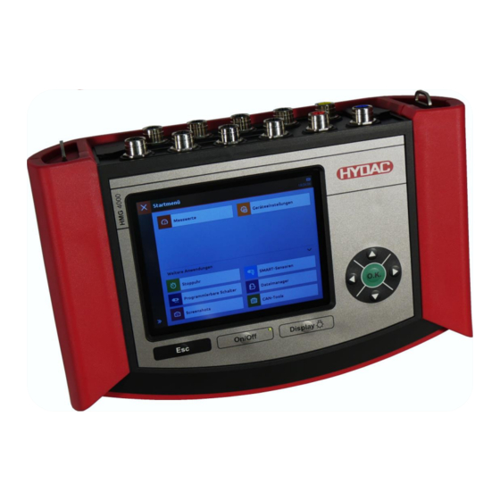
Page 12: The Hmg 4000 At A Glance
5-way navigation key Step-by-step navigation inside the display: "o.k." key for entering, completing, transferring or saving input Alternatively to the touchscreen, the HMG 4000 can be operated using the ESC key and the navigation and directional pad. Edition 2016-03-08 - V01 R04 [12] Part No.: 669950... -
Page 13: Connection Jacks
2.2 Connection jacks Analogue inputs (black) 8 input jacks (Channels A-H) for connecting normal analogue sensors (0-10 V, 4-20 mA, …), as well as HYDAC HSI sensors or SMART sensors, for example for measuring print, temperature, flow rate or oil condition. -
Page 14: First Steps With The Hmg 4000
Charge the battery with the help of the power supply unit provided before using the HMG 4000 for the first time. The battery built into the HMG 4000 starts charging as soon as the measuring device is supplied with power by the power adapter provided. -
Page 15: Switching Device On And Off
"Welcome screen". 3.4 Updating firmware To have the latest version of the HMG 4000 the firmware of the device needs to be updated provided an update file is available. Under certain circumstances, the settings saved in the HMG 4000 may no longer be legible after installing an update. -
Page 16: Managing The Hmg 4000
Handling HMG 4000 4 Managing the HMG 4000 4.1 Touchscreen operation The use and operation of the touchscreen is done with a few simple gestures (tap, swipe and drag movements as well as expanding and shrinking): Tap / Drag Expand Shrink 4.2 Display graphics setup... -
Page 17: Navigating In The Menu/Command Bar (Toolbar)
4.3 Navigating in the menu/command bar (toolbar) All settings and input options in the different applications and function menus of the HMG 4000 are largely self-explanatory and can be used intuitively. Using the button, you can directly access every display and from every menu point you can access the "Start menu". -
Page 18: Quickstart
Quickstart HMG 4000 5 Quickstart 5.1 Basic settings When starting the unit up for the first time the Welcome start-up screen appears. You now have to adjust the "Basic settings" required for the device to work. Select the desired date format, decimal point and keyboard layout. - Page 19 Quickstart HMG 4000 The entry of basic settings is now finished and you can use the HMG 4000. Complete the operation with "Finish" or go back to the previous screen by pressing "Back". The display then jumps to the measured value display.
-
Page 20: Measured Values
In delivery status, all eight analogue inputs are preset to "Automatic sensor detection" mode. If a HYDAC HSI or SMART sensor is now connected to one of the channels A-H, this is automatically detected and displayed accordingly. In the measured value display (see... -
Page 21: Starting Simple Recording
Quickstart HMG 4000 5.3 Starting simple recording To record measured value curves, you can access the "Recordings" menu from the measured value display using the button. Using the button you can access the "Start a recording" menu. You can adjust the corresponding settings for the recording here. -
Page 22: Start Menu
Start Menu HMG 4000 6 Start menu After switching on the HMG 4000, the screen will automatically switch to the measured value display. Using the button you can access the "Start menu". In the basic setting, only the following two applications are... -
Page 23: "Measured Values" Application
Measured values HMG 4000 7 "Measured values" application If sensors are connected and the channels set accordingly, their current measured values will be shown to you immediately. The following details will be shown to you by default in the measured value display: - Input channel (e.g. - Page 24 Measured values HMG 4000 Using the "Progression" opens a new window. Here, the current history of the measured values is shown as an ongoing graphic. (Also see chapter 7.2.5 "Display progression") 7.1.5 Resetting measured value zero point You can re-specify the zero point via button.
- Page 25 When removing a sensor or other system components make sure the system has been depressurized first. Failure to do this may pose a hazard to life and limb. Switching ON/OFF the HMG 4000 or one or more measured channels does not lead to the automatic deletion of the newly set zero point.
- Page 26 Measured values HMG 4000 To make changes to the measured value settings or the measured channels, access the measured value display in the "Measured value settings" menu via the button. You can adjust the settings and changes in the following menu...
-
Page 27: Settings For The Measured Value Display
Measured values HMG 4000 7.2 Settings for the measured value display You have the following setup options under this menu point: - Display filter - Trend duration - Measured values display - Show min./max values - Show bars - Show trend 7.2.1 Display filter... - Page 28 Measured values HMG 4000 7.2.2 Measured value display Upon selecting "Measured value display", a selection list for displaying the individual measured values appears: Table Panels - Size M Panels - Size L Panels - Size XL ...
- Page 29 Measured values HMG 4000 7.2.3 Displaying min./max. values After selecting "Show min./max. values", the min. and max. values will be shown together with the measured value. The min./max. values will continue to be displayed until either the display is switched off or the min./max.
- Page 30 Measured values HMG 4000 7.2.5 Displaying trend With the "Show trend" selection, you can also switch the trend display on and off in the measured value display. You can select for which period the history should be shown. You can choose from different time periods from 10 seconds to 60 minutes.
-
Page 31: Analogue Inputs (A-H)
HYDAC HSI or SMART sensor with automatic sensor detection or a standard analogue sensor is connected. With automatic sensor detection, the HMG 4000 applies all of the information and values directly from the connected HYDAC HSI or SMART sensor. With manual settings, you need to... - Page 32 Measured values HMG 4000 7.3.2 Name You can enter an optional designation for each measurement channel in the "Name" field. In this regard, a new window with a keyboard layout opens. Enter the desired name and save the input with "Apply".
- Page 33 Measured values HMG 4000 7.3.3 Analogue signal A selection list with different analogue signals is stored in the "Analogue signal" field. Here you can select an analogue signal from the existing entries. In delivery status, you will only find HSI, 0 to 10 V and 4 to 20 mA as well as PT 100 and PT 1000 at channel "H"...
-
Page 34: Digital Inputs (I, J)
Measured values HMG 4000 7.4 Digital inputs (I, J) Under this menu point you have a list of all of the digital measurement channels available in the HMG. To the left beside the corresponding channel you will find a box which you can use to switch the input on and off. - Page 35 Measured values HMG 4000 7.4.2 Digital state The measured value corresponds to the digital state at the input. It is updated every 0.1 ms. The measurement range goes from 0 to 1 and does not have any unit or decimal points.
- Page 36 Measured values HMG 4000 7.4.5 Times Times are measured here. The following can be measured: Cycle time (periodic time) Cyclical switch-on time Cyclical switch-off time Sum of switch-on times Sum of switch-off times Using the totalled up times, you can measure, for example, the switch- on times for units.
- Page 37 Measured values HMG 4000 7.4.7 Extended measurement A measurement can be freely configured here. Measurement used as a basis (Frequency / Pulse / Times / PWM) Timeout (with Frequency / PWM only) Times to be measured (with Times only) ...
-
Page 38: Can Bus/Hcsi (K)
HMG 4000 7.5 CAN bus/HCSI (K) When connecting up the HMG 4000 to an existing external CAN bus system or setting up an internal CAN bus system with HCSI sensors, the following basic safety steps need to be taken into consideration: The CAN bus can be connected to the HMG 4000 via the red jack "CAN"... - Page 39 A HCSI sensor can have one or more channels. In the sensor, a channel number is stored for every channel. A maximum of 28 channels can be allocated in the HMG 4000. Each channel number may only appear in the bus configuration just once and can be changed or reassigned at the HMG 4000.
- Page 40 HCSI Y splitter Bus termination Starting from HMG 4000, the bus setup may only be in one direction. The HMG 4000 must always be the first participant in the bus. Branching the HMG 4000 in two directions is not permitted!
- Page 41 Handling measured values The HMG 4000 sends a measured value query via the bus. After this, all connected HCSI sensors send their measured value. Once the HMG has received all measured values, it will send the next query. The refresh time of the measured values is specified automatically via the number of connected sensors.
- Page 42 CAN bus systems in particular. Before the HMG 4000 is set up in a running CAN bus system, corresponding presets and parameter specifications need to be adjusted for the HMG 4000 according to the type and model of the CAN bus system and the way it is connected.
- Page 43 Passive monitoring, do not acknowledge This setting must always be selected when the HMG 4000 is connected up to a CAN bus system so as to evaluate pre-defined messages passively. Active monitoring, acknowledging messages To test or to commission individual bus participants, for example, it is often necessary to acknowledge the receipt of messages.
- Page 44 Message type The HMG 4000 can evaluate the following message types: General J1939 Message CANopen PDO CANopen SDO...
- Page 45 Measured values HMG 4000 "General" message type In this mode, you can evaluate general CAN messages. For the message type "General" the following listed parameter settings are required. Name The entered name is used as the name of the measurement channel. If no name is entered here, "CAN channel x"...
- Page 46 Measured values HMG 4000 J1939 message In this mode, the data at a J1939 bus is taken from a transferred parameter group. The parameter groups here need to be transferred directly. (BAM and CMT cannot be evaluated!) In J1939 PGN mode, the following settings are required: ...
- Page 47 Measured values HMG 4000 CANopen PDO When transferring process data the mechanism of the Process Data Object (PDO) is available In this mode, the data is taken from a PDO. The following settings are required: Name The entered name is used as the name of the measurement channel. If no name is entered here, "CAN channel x"...
- Page 48 Measured values HMG 4000 CANopen SDO Service Data Objects (SDOs) are used for changes in the object folder and for status queries. Data can be written to an OD or read from one. The following settings are required for this: ...
-
Page 49: Calculations (L)
Measured values HMG 4000 7.6 Calculations (L) Here you have the option of defining and configuring up to four "virtual" measurement channels. The virtual measurement channels are always updated at 1 ms. The following settings are required for calculated channels: ... - Page 50 Measured values HMG 4000 Formula You can enter a formula here with which the other measurement channels can be offset. Example: "(A + B) * C2 + K4" The channels are addressed via their port letters and channel number. If a port has just one channel, the channel number can be omitted.
-
Page 51: Further Measurement Settings
Units with automatic sensor detection 7.7.1 Analogue signal list In the "Analogue signal list" you can currently see the input signals stored in the HMG 4000 and at which input channels these are used. You can add an additional analogue signal via the button. - Page 52 Measured values HMG 4000 7.7.3 Units with automatic sensor detection Here you can set which unit should be displayed for the measured values of HSI and HCSI sensors with automatic sensor detection in the measured value display. 7.7.4 Measurement unit for pressure ...
- Page 53 Measured values HMG 4000 7.7.6 Measurement unit for flow rate Apply from sensor l/min USG/min If "Apply from sensor" is selected, the corresponding unit of the sensor will be displayed. If "l/min" or "USG/min" is active, the measured value will be...
-
Page 54: Recordings
Recordings HMG 4000 8 Recordings The HMG 4000 provides very comprehensive and easy-to-use options in regard to recording and saving a measuring over a certain period of time. You can access the "Measured values" view via the Recording menu. In the measured value view, tap button in the menu/command bar (toolbar). -
Page 55: Starting A Recording
Recordings HMG 4000 8.1 Starting a recording To start a recording, tap the button in the toolbar. Then the "Start a recording" window will open. In this menu and all other submenus, all of the measurement parameters are listed for each recording type which can be selected. - Page 56 Recordings HMG 4000 If there is no power adapter hooked up to the HMG 4000, the maximum recording length for all recording procedures is also restricted by the capacity and the charge status of the battery. An ongoing recording can be stopped manually at any moment by tapping the button in the menu/ commands bar (tool bar).
-
Page 57: Recording Procedure
Recordings HMG 4000 8.2 Recording procedure Select one of the following options by tapping on the corresponding field: Endless recording This means that after starting the recording, the device permanently records measured values according to the presets. This happens until such a time as the recording is manually ended. - Page 58 "switched off" for it. Measurement rate Under this menu point you can set the time interval that the HMG 4000 reads in a measured value from the "active" sensors and stores it in the internal memory.
- Page 59 "switched off" for it. Measurement rate Under this menu point you can set the time interval that the HMG 4000 reads in a measured value from the "active" sensors and stores it in the internal memory.
- Page 60 "switched off" for it. Measurement rate Under this menu point you can set the time interval that the HMG 4000 reads in a measured value from the "active" sensors and stores it in the internal memory..
- Page 61 Recordings HMG 4000 Event settings Start condition If there is a "Start condition" for the measurement, you can activate it by tapping on the corresponding check box ( ). The following conditions are available for this: Digital input Select the corresponding digital input and enter the required switching status.
- Page 62 Recordings HMG 4000 Trigger events You can define up to 4 different trigger events (event 1 to 4) and activate them by tapping on the corresponding check box ( ). The following events are available for this: Digital input Select the corresponding digital input and enter the desired switching direction.
- Page 63 HMG 4000 Distribution of the measured values After starting the event-controlled recording, the HMG 4000 will begin to record the measured values for the set recording length. If the trigger event does not occur during this time, the oldest measured values are replaced with new measured values in the measured value memory.
- Page 64 Recordings HMG 4000 8.2.4 Event log The Event Log option enables you to store measured values as a table. A line in the table contains the current measured value, in addition, optionally, to the Min and Max value of each active channel.
- Page 65 Recordings HMG 4000 Event settings Start condition If there is a "Start condition" for the measurement, you can activate it by tapping on the corresponding check box ( ). The following conditions are available for this: Digital input Select the corresponding digital input and enter the required switching status.
- Page 66 Recordings HMG 4000 Trigger events You can define up to 4 different trigger events (event 1 to 4) and activate them by ticking the corresponding check box ( ). The following events are available for this: Digital input Select the corresponding digital input and enter the desired switching direction.
- Page 67 Recordings HMG 4000 After the end of a recording Under this menu point you can set how you wish to proceed after the automatic ending of the recording. Here you have the following options at your disposal: Stop recording The recording is stopped automatically and saves.
-
Page 68: Operation During Recording
Recordings HMG 4000 8.3 Operation during recording After starting the recording, the measurement in the entire time period (X axis) and measurement range (Y axis) will be displayed in scale. To the left of the Y axis, you can see which measurement channel is currently scaled to the Y axis. - Page 69 Recordings HMG 4000 In the menu/command list (toolbar), you have the following options for the graphical display of the recording while it is running: 8.3.1 Status You can view the current information on the running recording by pressing button. Edition 2016-03-08 - V01 R04 [69] Part No.: 669950...
- Page 70 Recordings HMG 4000 8.3.2 Measured values The current measured values, as shown in the measured value display are represented in corresponding panels by pressing the button. 8.3.3 Scale You can access the "Scale" submenu using the button. Here you can adjust the detail settings for the graphical display.
-
Page 71: Recordings
HMG 4000 8.4 Recordings Under the "Recordings" menu point, you can view a list of the recordings saved in the HMG 4000. By tapping on the corresponding field, you can open the desired recording and edit it. In the display, there is an adjacent... - Page 72 Recordings HMG 4000 In the menu/command list (toolbar), you have the following options for displaying and processing the recording: 8.4.1 Previous / Next view You can switch back and forth between the different edited views step by step using buttons.
- Page 73 Recordings HMG 4000 8.4.3 Scale to 100% With the function, the Y axis is scaled to the entire measurement range of the measurement channel (sensor) set for the scaling. 8.4.4 Settings You can open the "View settings" window with the function.
- Page 74 Recordings HMG 4000 Here, too, the differential between a selected starting and end point of a particular curve section (e.g. of a pressure pulse) can be rendered and measured. If you tap the "Tracker" function on the X axis, you can...
- Page 75 Recordings HMG 4000 8.4.8 Recording data With the function, you can view a summary of all the relevant data for the current recording. 8.4.9 Table With the function all of the recorded measured values are shown in a table. Tables are useful for displaying individual measured values.
-
Page 76: "Device Settings" Application
Device settings HMG 4000 9 "Device settings" application In the "Devices settings" menu, you can adjust the different basic settings for the HMG 4000 and manage the different device settings. 9.1 Region and language settings Under this menu point, you can... -
Page 77: Display Settings
Device settings HMG 4000 9.3 Display settings Under this menu point, you can adjust settings of the following display properties: Brightness (10% - 100%) Automatic switch-off (switch-off time up to 8 hours) Colour scheme (bright, dark) 9.4 Graphic settings... -
Page 78: Device Information
Memory allocation 9.6 Manage settings All measurement channels and device settings you adjusted in the HMG 4000 for the last measurement can be saved and the reloaded at a later time, for example, when the same measurement needs to be repeated multiple times. - Page 79 Device settings HMG 4000 9.6.1 Save You can save the current settings with the button. Here, select or create the desired target folder and enter a file name. Then complete the operation with "Save" or discard your input with "Cancel".
- Page 80 Device settings HMG 4000 9.6.3 Resetting Use the button to reset the HMG 4000. There are two selection options for this: Restore default settings (All saved files, settings and recordings remain intact) Restore delivery status (All saved files, settings and...
-
Page 81: 10 "Stopwatch" Application
Stop Watch HMG 4000 10 "Stopwatch" application This stopwatch permits the measuring of the elapsed time, interim times and the times between two or more events. The following functions are integrated into the menu/command bar (toolbar): Start Starts measuring Stop... -
Page 82: 11 "Programmable Switches" Application
Switch point settings Advanced settings Manage settings Working offline Using this button you can manage and edit the settings read out from a switch and saved to the HMG 4000. Edition 2016-03-08 - V01 R04 [82] Part No.: 669950... -
Page 83: Article / Serial Number
Programmable Switches HMG 4000 11.1 Article / Serial number Article and serial numbers are read out from the connected sensor and shown in the display. 11.2 Measured values In the menu point, the current measured value and the switch status of the switch outputs for the connected devices will be shown. -
Page 84: Advanced Settings
Programmable Switches HMG 4000 11.4 Advanced settings Under this menu point, you can adjust the advanced settings for the switch outputs and for the device. The content of this menu can vary depending on the device connected. Reset Reset sensor to default settings (delivery status) (Yes/No) ... -
Page 85: Managing Settings
Programmable Switches HMG 4000 11.5 Managing settings All device settings can be saved and then reloaded at a later time, for example, if the same settings are to be installed onto multiple devices. Furthermore, you can also delete specific settings here. - Page 86 Programmable Switches HMG 4000 11.5.2. Applying settings To load saved device settings, select the desired file and finish the operation with "Apply" or discard the operation with "Cancel". After applying the settings, a corresponding message appears. 11.5.3 Delete Using the button, you can delete the individual saved settings.
-
Page 87: 12 "Smart Sensor" Application
HMG 4000 12 "SMART sensor" application SMART sensors are HYDAC sensors, capable of outputting several different measured variables which are displayed as sub-channels of one measurement channel on the HMG. Depending on the sensor type, these variables are stored for an extended period in the unit's internal memory. -
Page 88: Connecting Smart Sensors
Establishing connection Use this button to connect the HMG 4000 with the connected SMART sensor. Working offline Use this button to manage the recordings and settings read out from the SMART sensor and saved to the HMG. -
Page 89: Smart Sensor Menu
SMART sensors HMG 4000 12.2 SMART sensor menu Once the connection has been made to the connected SMART sensor, the adjacent screen will open. The content of this and of all of the following menus can vary depending on the connected SMART sensor. - Page 90 12.2.3 Manage recordings In this menu item, you can manage the recordings saved in the SMART sensor. The recordings can be imported to the HMG 4000, displayed and edited (see chapter 8. "Recordings"). You can access the "Settings" window using the button.
- Page 91 SMART sensors HMG 4000 12.2.6 Address settings This menu enables you to assign a bus address to a sensor. Here, select a value from the list. Complete the operation with "Apply" or discard the process with "Cancel". Bus addresses must be assigned when the SMART sensor is operated in a bus system.
-
Page 92: 13 "Can Tools" Application
You can connect individual bus participants to the HMG 4000 and configure them for bus operation. Logging message traffic in the bus system You can switch the HMG 4000 to a CAN bus system and log the entire message traffic. ... -
Page 93: Basic Settings
Internal load resistor The internal load resistor needs to be connected if the HMG 4000 is hooked up to the CAN bus system at the end of the bus line as the "last participant", rather than using a branch line. -
Page 94: Establishing Connection
CAN-Tools HMG 4000 13.2 Establishing connection In this menu, you have the following options of establishing a connection to the connected participant or bus system: 13.2.1. Messages In this window, you can keep up to date with current message traffic. - Page 95 CAN-Tools HMG 4000 Using the button, you can configure and send messages. If the setting “Cyclical Transmission“ is selected, you can switch on or switch off the cyclical transmission process by tapping on the corresponding message line. If the setting “Cyclical Transmission“...
- Page 96 Search This function is only available to HYDAC ELECTRONIC GmbH devices. The HMG 4000 automatically searches for the EDS file which corresponds to the participant and opens it. The corresponding data is generated from the "1018, IdentityObject"...
- Page 97 ID of one or more participants for which no EDS file is yet saved to the HMG 4000. The data can be entered manually and correspond to the data from parameter 1018.
- Page 98 The values currently set in the device for node ID and baud rate as well as the device status and configuration do not have to be known for the search to function! All information is read out using the search function of the HMG 4000. After tapping "Continue", the HMG begins to search for connected participants.
- Page 99 CAN-Tools HMG 4000 If the connected device is "found" (detected), you can change the node ID and baud rate according to the requirements. After tapping "Continue", the connected device is configured with the changed settings. Then finish the operation with "Finish"...
-
Page 100: 14 "Screenshots" Application
Screenshots HMG 4000 14 "Screenshots" application In this menu you can manage the screenshots created in the HMG 4000. To show a screenshot on the display, quickly tap the corresponding file. In display mode, you can use the buttons to swipe back and forth between saved screenshots. -
Page 101: 15 "File Manager" Application
File manager HMG 4000 15 "File Manager" application In this application, you can easily manage all of the user files stored on the HMG 4000, like recordings, settings, parameter sets, etc. 15.1 Working with the file manager The device has an internal data... - Page 102 File manager HMG 4000 With the file manager, you work at "File level", that is, all folders and files are shown and you can work with them like in Explorer. In this regard, you can avail of the following tools from the menu/command list: ...
- Page 103 The loading time of a folder depends on the number of subfolders and files contained. (Files > 2 GB will not be shown!). All saved files can be transferred via the USB device interface from the HMG 4000 to a PC or back to the HMG 4000.
-
Page 104: Restrictions To The File Manager
File manager HMG 4000 15.2 Restrictions to the file manager The file manager evaluates just the first 55 characters of folder and file names. Longer names will be shortened. Files, which are larger than 2 GB, will also not be shown. -
Page 105: Pc Link
It is not possible to operate the HMG 4000 in "PC mode". - In this status, the touchscreen and operating keys are non-functioning! - If the HMG is connected to a PC during a running recording,... -
Page 106: Cleaning / Maintenance / Update
HMG 4000 16 Cleaning / Maintenance / Update 16.1 Cleaning Before cleaning, switch off the HMG 4000 and disconnect the device from the power supply. Do not use any aggressive substances when cleaning, e.g. solvents, alcohol, screen cleaners, petroleum ether or similar chemicals. -
Page 107: Software Update
Update files for the device always have to be transferred manually from the PC to the HMG 4000 and into the folder "HMG / Updates". Multiple update files can be saved to the device at the same time. - Page 108 This describes the effects the installation has on the HMG 4000 and if its saved files were affected by it. If the HMG 4000 is not connected to the power and the battery charge is too low, the adjacent message will appear.
-
Page 109: Changing Battery
Cleaning/ Maintenance/ Updating HMG 4000 16.5 Changing battery Loosen and remove the fixing screw in the battery compartment cover. Move the battery compartment cover downward, over and past the block. Loosen the connection plug of the battery pack. Connect up the new battery pack,... -
Page 110: Dc-Dc Ground Bond
Cleaning/ Maintenance/ Updating HMG 4000 16.6 DC-DC ground bond The HMG 4000 performs galvanic separation of the DC power supply provided by the power adapter internally. In rare and exceptional circumstances, it may happen with unfavourable network setups that "ripple voltages" are recorded (e.g. 50 Hz "mains hums") when measuring with connected power supply units. -
Page 111: Accessories
Accessories HMG 4000 17 Accessories 17.1 Sensors Pressure measuring transducer with HSI interface: -1 ... 9 bar HDA 4748-H-0009-000(-1...+9bar) Mat. no. 909429 0 ... 16 bar HDA 4748-H-0016-000 Mat. no. 909425 0 ... 60 bar HDA 4748-H-0060-000 Mat. no. 909554 0 ... -
Page 112: Sensor Cables
Mat. no. 6040851 5 m length ZBE 30-05(Sensor cable M12x1, 5-pin) 2m Mat. no. 6040852 17.3 Other accessories Case for HMG 4000 and accessories Mat. no. 6179836 ZBE 31 (car battery charger for HMG 2x/3x/4x) Mat. no. 909739 HCSI Y splitter Mat. -
Page 113: Technical Data
8 channels via eight M12x1 Ultra Lock flanged jacks (5-pin) Description Channel A - Channel H Input signals HYDAC HSI analogue sensors HYDAC HSI SMART sensors Voltage ranges: 0 - 50 V, 0 - 10 V, 0 - 4.5 V, -10 - +10 V Current ranges:... -
Page 114: Programming Interface
Notes HMG 4000 18.1.4 Calculated channels Quantity 4 channels via virtual port L Description Channel L1 - Channel L4 Possible operations +, -, *, / sqr, sqrt, ln, log abs, π, e, x Refresh rate 1 ms 18.2 Programming interface... -
Page 115: Interfaces
Notes HMG 4000 18.5 Interfaces 18.5.1 USB Host Plug connection USB socket, Type A, screened USB Standard 2.0 (USB Full speed) Transmission rate 12 Mbit/s Voltage supply 5 V DC Power supply 100 mA max. Protection Short circuit protection against GND (0 V ) 18.5.2 USB Device... -
Page 116: Port Allocations
Notes HMG 4000 18.9 Port allocations 18.9.1 Measurement channels: Socket Colour Chann Pin 1 Pin 2 Pin 3 Pin 4 Pin 5 A … G black A … G n.c. Signal n.c. Signal black n.c. PT 100 PT 100 PT 100 n.c. -
Page 117: Dimensions And Weight
Notes HMG 4000 18.9.2 Interfaces: Socket Transmission rate Function Max. 12 Mbit / s Connection of slaves Master (USB Full speed) (USB memory stick) Max. 480 Mbit / s PC interface Slave (USB High speed) 18.9.3 Power supply Socket Connection Function Round plug 2.1 mm... - Page 118 Notes HMG 4000 ____________________________________________ ____________________________________________ ____________________________________________ ____________________________________________ ____________________________________________ ____________________________________________ ____________________________________________ ____________________________________________ ____________________________________________ ____________________________________________ ____________________________________________ ____________________________________________ ____________________________________________ ____________________________________________ ____________________________________________ ____________________________________________ ____________________________________________ ____________________________________________ ____________________________________________ ____________________________________________ ____________________________________________ ____________________________________________ ____________________________________________ ____________________________________________ ____________________________________________ ____________________________________________ Edition 2016-03-08 - V01 R04 [118] Part No.: 669950...
- Page 119 Notes HMG 4000 ____________________________________________ ____________________________________________ ____________________________________________ ____________________________________________ ____________________________________________ ____________________________________________ ____________________________________________ ____________________________________________ ____________________________________________ ____________________________________________ ____________________________________________ ____________________________________________ ____________________________________________ ____________________________________________ ____________________________________________ ____________________________________________ ____________________________________________ ____________________________________________ ____________________________________________ ____________________________________________ ____________________________________________ ____________________________________________ ____________________________________________ ____________________________________________ ____________________________________________ ____________________________________________ Edition 2016-03-08 - V01 R04 [119] Part No.: 669950...
- Page 120 For applications and operating conditions not described, please contact the relevant technical department. If you have any questions, suggestions, or encounter any problems of a technical nature, please contact your HYDAC representative. Subject to technical modifications. Edition 2016-03-08 - V01 R04 [120] Part No.: 669950...
Need help?
Do you have a question about the HMG 4000 and is the answer not in the manual?
Questions and answers