Vega VEGAPULS 61 Operating Instructions Manual
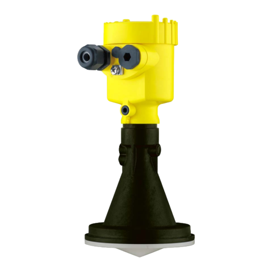
Radar sensor for continuous level
measurement of liquids
Hide thumbs
Also See for VEGAPULS 61:
- Operating instructions manual (100 pages) ,
- Quick setup manual (24 pages) ,
- Safety manual (16 pages)

Related Manuals for Vega VEGAPULS 61


Summary of Contents for Vega VEGAPULS 61
-
Page 1: Operating Instructions
Operating Instructions Radar sensor for continuous level measurement of liquids VEGAPULS 61 4 … 20 mA/HART - two-wire Document ID: 36499... -
Page 2: Table Of Contents
Measured value indication - Selection of national language ........... 41 Parameter adjustment ....................41 Saving the parameterisation data ................... 59 Setup with PACTware Connect the PC ......................60 Parameter adjustment ....................61 Saving the parameterisation data ................... 62 VEGAPULS 61 • 4 … 20 mA/HART - two-wire... - Page 3 11.4 Trademark ........................94 Safety instructions for Ex areas Take note of the Ex specific safety instructions for Ex applications. These instructions are attached as documents to each instrument with Ex approval and are part of the operating instructions manual. Editing status: 2017-04-03 VEGAPULS 61 • 4 … 20 mA/HART - two-wire...
-
Page 4: About This Document
This arrow indicates a single action. Sequence of actions Numbers set in front indicate successive steps in a procedure. Battery disposal This symbol indicates special information about the disposal of bat- teries and accumulators. VEGAPULS 61 • 4 … 20 mA/HART - two-wire... -
Page 5: For Your Safety
During work on and with the device the required personal protective equipment must always be worn. Appropriate use VEGAPULS 61 is a sensor for continuous level measurement. You can find detailed information about the area of application in chapter "Product description". Operational reliability is ensured only if the instrument is properly used according to the specifications in the operating instructions manual as well as possible supplementary instructions. -
Page 6: Eu Conformity
The instrument must be permanently mounted on a closed vessel made of metal, reinforced concrete, or comparable attenuating materials • Flanges, process fittings and mounting accessories must ensure the microwave impermeability of the vessel and not let the radar signal escape to the outside VEGAPULS 61 • 4 … 20 mA/HART - two-wire... -
Page 7: Radio License For Usa
This device must accept any interference, including interference that may cause undesired operation of the device This device has been approved for both closed containers and open- air environments with the following limitations: VEGAPULS 61 • 4 … 20 mA/HART - two-wire... - Page 8 Cuves fermées : Pour les installations impliquant une inclinaison lors de l'installation : cet appareil ne doit être installé que dans une cuve totalement fermée en en métal, en béton ou en matière plas- VEGAPULS 61 • 4 … 20 mA/HART - two-wire...
-
Page 9: Environmental Instructions
That is why we have introduced an environment management system with the goal of continuously improving company environmental pro- tection. The environment management system is certified according to DIN EN ISO 14001. Please help us fulfil this obligation by observing the environmental instructions in this manual: • Chapter "Packaging, transport and storage" • Chapter "Disposal" VEGAPULS 61 • 4 … 20 mA/HART - two-wire... -
Page 10: Product Description
Alternatively, you can access the data via your smartphone: • Download the smartphone app "VEGA Tools" from the "Apple App Store" or the "Google Play Store" • Scan the Data Matrix code on the type label of the instrument or •... -
Page 11: Principle Of Operation
The respective scope of delivery results from the order specification. Principle of operation Application area The VEGAPULS 61 is a radar sensor for continuous level measure- ment of liquids under simple process conditions. Dependent on the application range, different versions are used: • Level measurement of aggressive liquids in small vessels: encap- sulated antenna system •... -
Page 12: Packaging, Transport And Storage
Smartphone/tablet (iOS or Android operating system) • PC/notebook with Bluetooth USB adapter (Windows operating system) You can find further information in the operating instructions "Display and adjustment module PLICSCOM" (Document-ID 27835). Bluetooth function with VEGADIS 82 can only be used at a later date. VEGAPULS 61 • 4 … 20 mA/HART - two-wire... - Page 13 USB interface of a PC. For parameter adjustment of these instruments, the adjustment software PACTware with VEGA-DTM is required. You can find further information in the operating instructions "Interface adapter VEGACONNECT" (Document-ID 32628). The VEGADIS 81 is an external display and adjustment unit for VEGA VEGADIS 81 plics sensors. ®...
- Page 14 The supplementary electronics is a replacement part for 4 … 20 mA/ ics for double chamber HART sensors with double chamber housing. housing You can find further information in the operating instructions "Supple- mentary electronics for 4 … 20 mA/HART - two-wire" (Document-ID 42764). VEGAPULS 61 • 4 … 20 mA/HART - two-wire...
-
Page 15: Mounting
The free openings for the cable glands are therefore covered with red dust protection caps as transport protection. The dust protection caps do not provide sufficient protection against moisture. VEGAPULS 61 • 4 … 20 mA/HART - two-wire... -
Page 16: Collar Or Adapter Flange
Max. torque, see chapter "Technical data". Required tools: Allen wrench size 4. There are two ways to screw the strap onto the sensor. Depending on the selected version, the sensors can be swivelled in the strap as follows: VEGAPULS 61 • 4 … 20 mA/HART - two-wire... -
Page 17: Mounting Instructions
3. Tighten all screws with the torque stated in the technical data Polarisation The emitted radar impulses of the radar sensor are electromagnetic waves. The polarisation is the direction of the electrical wave compo- nent. By turning the instrument in the connection flange or mounting boss, the polarisation can be used to reduce the effects of false echoes. The position of the polarisation is marked on the process fitting of the instrument. VEGAPULS 61 • 4 … 20 mA/HART - two-wire... - Page 18 Fig. 6: Mounting of the radar sensor on round vessel tops In vessels with conical bottom it can be advantageous to mount the sensor in the centre of the vessel, as measurement is then possible down to the bottom. VEGAPULS 61 • 4 … 20 mA/HART - two-wire...
- Page 19 Socket with encapsulated The socket piece should be dimensioned in such a way that the an- antenna system tenna end protrudes at least 10 mm (0.4 in) out of the socket. VEGAPULS 61 • 4 … 20 mA/HART - two-wire...
- Page 20 4 Mounting Fig. 9: Recommended socket mounting If the reflective properties of the medium are good, you can mount VEGAPULS 61 on sockets which are higher than the length of the antenna. You will find recommended values for socket heights in the following illustration. The socket end should be smooth and burr-free, if possible also rounded. After installation you must carry out a false signal suppression.
- Page 21 The below charts specify the max. socket length h depending on the diameter d. Socket diameter d Socket length h 80 mm ≤ 300 mm VEGAPULS 61 • 4 … 20 mA/HART - two-wire...
- Page 22 Fig. 14: Cover flat, large-area profiles with deflectors Agitators If there are agitators in the vessel, a false signal suppression should be carried out with the agitators in motion. This ensures that the interfering reflections from the agitators are saved with the blades in different positions. VEGAPULS 61 • 4 … 20 mA/HART - two-wire...
-
Page 23: Measurement Setup - Pipes
Under these prerequisites, the measurement of products with low dielectric values (ε value ≤ 1.6) is possible. Note the following illustrations and instructions for measurement in a surge pipe. Information: Measurement in a surge pipe is not recommended for extremely adhesive products. VEGAPULS 61 • 4 … 20 mA/HART - two-wire... - Page 24 Polarisation marking Thread or flange on the instrument Vent hole Holes Welding connection through U-profile Ball valve with complete opening Surge pipe end Reflector sheet 10 Fastening of the surge pipe VEGAPULS 61 • 4 … 20 mA/HART - two-wire...
- Page 25 • A false signal suppression with the installed sensor is recom- mended but not mandatory • The measurement through a ball valve with unrestricted channel is possible VEGAPULS 61 • 4 … 20 mA/HART - two-wire...
- Page 26 • An extension via welding neck flanges or pipe collars is not recom- mended. Measurement in the An alternative to measurement in a surge pipe is measurement in a bypass tube bypass tube outside of the vessel. VEGAPULS 61 • 4 … 20 mA/HART - two-wire...
- Page 27 • A false signal suppression with the installed sensor is recom- mended but not mandatory • The measurement through a ball valve with unrestricted channel is possible VEGAPULS 61 • 4 … 20 mA/HART - two-wire...
-
Page 28: Measurement Setup - Flow
In general, the following points must be observed: • Install the sensor on the headwater side • Installation in the centre of the flume and vertical to the liquid surface • Distance to the overfall orifice • Distance of orifice opening above ground • Min. distance of the orifice opening to tailwater • Min. distance of the sensor to max. storage level VEGAPULS 61 • 4 … 20 mA/HART - two-wire... - Page 29 In general, the following points must be observed: • Installation of the sensor at the inlet side • Installation in the centre of the flume and vertical to the liquid surface • Distance to the Venturi flume • Min. distance of the sensor to max. storage level VEGAPULS 61 • 4 … 20 mA/HART - two-wire...
-
Page 30: Connecting To Power Supply
In the case of instrument housings with self-sealing NPT threads, it is not possible to have the cable entries screwed in at the factory. The free openings for the cable glands are therefore covered with red dust protection caps as transport protection. VEGAPULS 61 • 4 … 20 mA/HART - two-wire... -
Page 31: Connecting
4. Remove approx. 10 cm (4 in) of the cable mantle, strip approx. 1 cm (0.4 in) of insulation from the ends of the individual wires 5. Insert the cable into the sensor through the cable entry VEGAPULS 61 • 4 … 20 mA/HART - two-wire... - Page 32 7. Check the hold of the wires in the terminals by lightly pulling on them 8. Connect the screen to the internal ground terminal, connect the external ground terminal to potential equalisation VEGAPULS 61 • 4 … 20 mA/HART - two-wire...
-
Page 33: Wiring Plan, Single Chamber Housing
The following illustrations apply to the non-Ex as well as to the Ex-ia version. Electronics compartment 4...20mA 6 7 8 Fig. 24: Electronics compartment - double chamber housing Internal connection to the terminal compartment For display and adjustment module or interface adapter VEGAPULS 61 • 4 … 20 mA/HART - two-wire... - Page 34 Ground terminal for connection of the cable screen Terminal compart- ment - Radio module PLICSMOBILE Status SIM-Card Test Fig. 26: Terminal compartment - Radio module PLICSMOBILE Voltage supply You can find detailed information on connection in the supplementary instructions "PLICSMOBILE GSM/GPRS radio module". VEGAPULS 61 • 4 … 20 mA/HART - two-wire...
-
Page 35: Wiring Plan, Ex-D-Ia Double Chamber Housing
Ground terminal for connection of the cable screen Plug M12 x 1 for external display and adjustment unit Fig. 29: Top view of the plug connector Pin 1 Pin 2 Pin 3 Pin 4 VEGAPULS 61 • 4 … 20 mA/HART - two-wire... -
Page 36: Double Chamber Housing With Vegadis-Adapter
Pin 1 Pin 2 Pin 3 Pin 4 Contact pin Colour, connection ca- Terminal, electronics ble in the sensor module Pin 1 Brown Pin 2 White Pin 3 Blue Pin 4 Black VEGAPULS 61 • 4 … 20 mA/HART - two-wire... -
Page 37: Wiring Plan - Version Ip 66/Ip 68, 1 Bar
As soon as a plausible measured value is found, the corresponding current is outputted to the signal cable. The value corresponds to the actual level as well as the settings already carried out, e.g. factory setting. VEGAPULS 61 • 4 … 20 mA/HART - two-wire... -
Page 38: Set Up With The Display And Adjustment Module
The display and adjustment module is powered by the sensor, an ad- ditional connection is not necessary. Fig. 33: Installing the display and adjustment module in the electronics compart- ment of the single chamber housing VEGAPULS 61 • 4 … 20 mA/HART - two-wire... -
Page 39: Adjustment System
Adjustment system Fig. 35: Display and adjustment elements LC display Adjustment keys • Key functions [OK] key: VEGAPULS 61 • 4 … 20 mA/HART - two-wire... - Page 40 (with inspection window) of the sensor housing. Fig. 36: Display and adjustment elements - with adjustment via magnetic pen LC display Magnetic pen Adjustment keys Bluetooth symbol Lid with inspection window VEGAPULS 61 • 4 … 20 mA/HART - two-wire...
-
Page 41: Measured Value Indication - Selection Of National Language
The instrument is adapted to the application conditions via the pa- rameter adjustment. The parameter adjustment is carried out with an adjustment menu. Main menu The main menu is divided into five sections with the following func- tions: Setup: Settings, e.g., for measurement loop name, medium, applica- tion, vessel, adjustment, signal output VEGAPULS 61 • 4 … 20 mA/HART - two-wire... - Page 42 With bulk solids, the additional interfering fac- tors are dust generation, angle of repose and secondary echoes from the vessel wall. To adapt the sensor to these different measuring conditions, the selection "Liquid" or "Bulk solid" should be made in this menu item. VEGAPULS 61 • 4 … 20 mA/HART - two-wire...
- Page 43 Plastic tank • Transportable plastic tank • Open water (gauge measurement) • Open flume (flow measurement) • Rain water overfall (weir) Storage tank: • Setup: large-volumed, upright cylindrical, spherical • Medium speed: slow filling and emptying • Process/measurement conditions: VEGAPULS 61 • 4 … 20 mA/HART - two-wire...
- Page 44 – Large agitator blades of metal – Vortex breakers, heating spirals • Process/measurement conditions: – Condensation, buildup by movement – Strong spout generation – Very agitated surface, foam generation • Properties, sensor: VEGAPULS 61 • 4 … 20 mA/HART - two-wire...
- Page 45 – Separation of oil and water possible – Overfilling into the antenna possible • Properties, sensor: – Measurement speed optimized through little averaging – Entering the tube inside diameter takes the running time shift into consideration – Echo detection sensitivity reduced – False signal suppression recommended VEGAPULS 61 • 4 … 20 mA/HART - two-wire...
- Page 46 – Exact measurement result required – Distance to the water surface normally relatively large • Properties, sensor: – Stable and reliable measured values through frequent averag- – Insensitive in the close range VEGAPULS 61 • 4 … 20 mA/HART - two-wire...
- Page 47 Through this selection the operating range of the sensor is adapted measuring range to the vessel height, which considerably increases measurement certainty under different basic conditions. The min. adjustment must be carried out independently of this. VEGAPULS 61 • 4 … 20 mA/HART - two-wire...
- Page 48 Setup - Min. adjustment Proceed as follows: 1. Select the menu item "Setup" with [->] and confirm with [OK]. Now select with [->] the menu item "Min. adjustment" and confirm with [OK]. VEGAPULS 61 • 4 … 20 mA/HART - two-wire...
- Page 49 5. Save settings with [OK] Setup - Damping To damp process-dependent measured value fluctuations, set an integration time of 0 … 999 s in this menu item. VEGAPULS 61 • 4 … 20 mA/HART - two-wire...
- Page 50 Select menu items and show data • Read data from sensor into the display and adjustment module. Caution: When the PIN is active, adjustment via PACTware/DTM as well as other systems is also blocked. VEGAPULS 61 • 4 … 20 mA/HART - two-wire...
- Page 51 In this menu item, the device status is displayed. status Diagnostics - Peak values The respective min. and max. measured distance values are saved in (distance) the sensor. The values are displayed in the menu item "Peak values". VEGAPULS 61 • 4 … 20 mA/HART - two-wire...
- Page 52 5. Set the requested numerical value with [+] and [->]. 6. Push [OK] Note: During simulation, the simulated value is outputted as 4 … 20 mA cur- rent value and digital HART signal. VEGAPULS 61 • 4 … 20 mA/HART - two-wire...
- Page 53 Additional adjustments - In this menu item you select the measured variable of the system and Instrument units the temperature unit. VEGAPULS 61 • 4 … 20 mA/HART - two-wire...
- Page 54 Check the distance to the product surface, because if an incorrect (too large) value is entered, the existing level will be saved as a false signal. The level would then no longer be detectable in this area. VEGAPULS 61 • 4 … 20 mA/HART - two-wire...
- Page 55 Additional settings - PIN Entering a 4-digit PIN protects the sensor data against unauthorized access and unintentional modification. In this menu item, the PIN is displayed or edited and changed. However, this menu item is only available if adjustment is enabled in the menu "Setup". VEGAPULS 61 • 4 … 20 mA/HART - two-wire...
- Page 56 Peak values, measured value: Resets the measured min. and max. distances to the current measured value. The following table shows the default values of the instrument. De- pending on the instrument version, not all menu items are available or some may be differently assigned: VEGAPULS 61 • 4 … 20 mA/HART - two-wire...
-
Page 57: Additional Settings
Address 0 Additional settings - The sensor offers the HART modes standard and Multidrop. In this HART mode menu item you specify the HART mode and enter the address for Multidrop. The mode "standard" with the fixed address 0 means outputting the measured value as a 4 … 20 mA signal. VEGAPULS 61 • 4 … 20 mA/HART - two-wire... - Page 58 In this menu item, the hardware and software version of the sensor is displayed. The 4 … 20 mA signal of the sensor is switched off. The sensor uses a constant current of 4 mA. The measuring signal is transmitted exclusively as a digital HART signal. VEGAPULS 61 • 4 … 20 mA/HART - two-wire...
-
Page 59: Saving The Parameterisation Data
If it is necessary to exchange a sensor, the display and adjustment module is inserted into the replacement instrument and the data are likewise written into the sensor via the menu item "Copy device settings". VEGAPULS 61 • 4 … 20 mA/HART - two-wire... -
Page 60: Setup With Pactware
Interface adapter, for example VEGACONNECT 4 Note: With power supply units with integrated HART resistance (internal resistance approx. 250 Ω), an additional external resistance is not necessary. This applies, e.g. to the VEGA instruments VEGATRENN 149A, VEGAMET 381, VEGAMET 391. Common Ex separators are VEGAPULS 61 • 4 … 20 mA/HART - two-wire... -
Page 61: Parameter Adjustment
In the standard version, all functions for complete setup are already included. An assistant for simple project configuration simplifies the adjustment considerably. Saving/printing the project as well as import/export functions are also part of the standard version. VEGAPULS 61 • 4 … 20 mA/HART - two-wire... -
Page 62: Saving The Parameterisation Data
CD from the agency serving you. Saving the parameterisation data We recommend documenting or saving the parameterisation data via PACTware. That way the data are available for multiple use or service purposes. VEGAPULS 61 • 4 … 20 mA/HART - two-wire... -
Page 63: Set Up With Other Systems
This software is updated via the Internet and new EDDs are automatically accepted into the device catalogue of this software after they are released by the manufacturer. They can then be transferred to a Field Communicator. VEGAPULS 61 • 4 … 20 mA/HART - two-wire... -
Page 64: Diagnosis, Asset Management And Service
Changes in the measure- ment conditions during operation or buildup on the sensor can thus be recognized. The echo curve of the setup is stored via: • PC with PACTware/DTM • Control system with EDD • Display and adjustment module VEGAPULS 61 • 4 … 20 mA/HART - two-wire... -
Page 65: Asset Management Function
Plan in maintenance for the instrument because a failure is expected in the near future (e.g. due to buildup). This status message is inactive by default. It can be activated by the user via PACTware/DTM or EDD. VEGAPULS 61 • 4 … 20 mA/HART - two-wire... - Page 66 Check or correct installation Bit 10 of Byte 0 … 5 height/measuring range and/or parameter settings Installation/Setup • • Max. measuring range of the Use an instrument with bigger error instrument not sufficient measuring range VEGAPULS 61 • 4 … 20 mA/HART - two-wire...
- Page 67 Error in the non- active linearisation table • • M502 Hardware error EEPROM Exchanging the electronics Bit 2 of • Send instrument for repair Byte 14 … 24 Error in the diag- nostics memory VEGAPULS 61 • 4 … 20 mA/HART - two-wire...
-
Page 68: Rectify Faults
• • Current signal greater than Electronics module in the Exchange the instrument or send it in for repair 22 mA or less than 3.6 mA sensor defective VEGAPULS 61 • 4 … 20 mA/HART - two-wire... - Page 69 Determine the reason for the signal has changed (e.g. con- changed false signals, carry out densation, buildup); false signal false signal suppression, e.g. suppression no longer matches with condensation actual conditions VEGAPULS 61 • 4 … 20 mA/HART - two-wire...
- Page 70 The antenna • sensor goes into overfill protec- Use a sensor with a more suit- time tion mode. The max. level (0 m able antenna distance) as well as the status message "Overfill protection" are outputted. VEGAPULS 61 • 4 … 20 mA/HART - two-wire...
-
Page 71: Exchanging The Electronics Module
24 hour service hotline Should these measures not be successful, please call in urgent cases the VEGA service hotline under the phone no. +49 1805 858550. The hotline is also available outside normal working hours, seven days a week around the clock. -
Page 72: Software Update
Attach the completed form and, if need be, also a safety data sheet outside on the packaging • Please contact the agency serving you to get the address for the return shipment. You can find the agency on our home page www.vega.com. VEGAPULS 61 • 4 … 20 mA/HART - two-wire... -
Page 73: Dismount
Pass the instrument directly on to a spe- cialised recycling company and do not use the municipal collecting points. These may be used only for privately used products according to the WEEE directive. VEGAPULS 61 • 4 … 20 mA/HART - two-wire... -
Page 74: Supplement
DIN from DN 80, ASME from 3", JIS from DN 100 10K Ʋ Hygienic fittings Clamp, slotted nut according to DIN 11851, Tuchenha- gen Varivent Weight depending on process fitting and 0.7 … 3.4 kg (1.543 … 7.496 lbs) housing material VEGAPULS 61 • 4 … 20 mA/HART - two-wire... - Page 75 Standard electronics Max. measuring range 35 m (114.8 ft) Recommended measuring range Ʋ Encapsulated antenna system up to 10 m (32.81 ft) Ʋ Plastic horn antenna up to 20 m (65.62 ft) VEGAPULS 61 • 4 … 20 mA/HART - two-wire...
- Page 76 > 200 mm (7.874 in) Ʋ Reflector Flat plate reflector Ʋ False reflections Biggest false signal, 20 dB smaller than the useful signal Deviation with liquids See following diagrams Default values can be assigned individually. VEGAPULS 61 • 4 … 20 mA/HART - two-wire...
- Page 77 EN 61326 Specifications apply also to the current output Temperature drift - Current output ±0.03 %/10 K relating to the 16 mA span max. ±0.3 % Deviation in the current output due to digital/analogue conversion Ʋ Non-Ex and Ex-ia version < ±15 µA Ʋ Ex-d-ia version < ±40 µA VEGAPULS 61 • 4 … 20 mA/HART - two-wire...
-
Page 78: Ambient Conditions
Ʋ with mounting strap 1 g at 5 … 200 Hz according to EN 60068-2-6 (vibration with resonance) Time span after a sudden measuring distance change by max. 0.5 m in liquid applications, max 2 m with bulk solids applications, until the output signal has taken for the first time 90 % of the final value (IEC 61298-2). Outside the specified beam angle, the energy level of the radar signal is 50% (-3 dB) less. EIRP: Equivalent Isotropic Radiated Power. VEGAPULS 61 • 4 … 20 mA/HART - two-wire... - Page 79 8 mm (0.315 in) Ʋ Colour - Non-Ex version Black Ʋ Colour - Ex-version Blue Display and adjustment module Display element Display with backlight Measured value indication Ʋ Number of digits VEGAPULS 61 • 4 … 20 mA/HART - two-wire...
- Page 80 Via the digital output signal (depending on the electron- ics version) Range -40 … +85 °C (-40 … +185 °F) Resolution < 0.1 K Accuracy ±3 K Voltage supply Operating voltage U Ʋ Non-Ex instrument 9.6 … 35 V DC VEGAPULS 61 • 4 … 20 mA/HART - two-wire...
- Page 81 Type 6P IP 68 (1 bar) Double chamber IP 66/IP 68 (0.2 bar) Type 6P IP 68 (1 bar) Stainless steel (electro- Single chamber IP 66/IP 68 (0.2 bar) Type 6P polished) VEGAPULS 61 • 4 … 20 mA/HART - two-wire...
-
Page 82: Dimensions
Instruments with approvals can have different technical specifications depending on the version. For that reason the associated approval documents of these instruments have to be carefully noted. They are part of the delivery or can be downloaded under www.vega.com, "Instrument search (serial number)" as well as in the download area. 11.2 Dimensions The following dimensional drawings represent only an extract of all possible versions. - Page 83 Fig. 61: Housing version with protection rating IP 66/IP 68 (1 bar) - with integrated display and adjustment module the housing is 9 mm/0.35 in higher Aluminium - single chamber Aluminium - double chamber VEGAPULS 61 • 4 … 20 mA/HART - two-wire...
- Page 84 Fig. 63: Housing version with protection rating IP 66/IP 68 (1 bar) - with integrated display and adjustment module the housing is 9 mm/0.35 in higher Stainless steel single chamber (electropolished) Stainless steel single chamber (precision casting) Stainless steel double chamber housing (precision casting) VEGAPULS 61 • 4 … 20 mA/HART - two-wire...
- Page 85 11 Supplement VEGAPULS 61, threaded version SW 50 mm (1.97") G1½A / 1½ NPT ø 39 mm (1.54") Fig. 64: VEGAPULS 61, threaded version G1½ and 1½ NPT VEGAPULS 61 • 4 … 20 mA/HART - two-wire...
- Page 86 Fig. 65: VEGAPULS 61, hygienic fitting Clamp 2" (ø64 mm) and 3" (ø91 mm) PN 16 DIN 32676, ISO 2852/316L Slotted nut according to DIN 11851 DN 50 and DN 80 Tuchenhagen Varivent DN 32 VEGAPULS 61 • 4 … 20 mA/HART - two-wire...
- Page 87 (4.92") 2,5 mm (0.10") 75 mm (2.95") 107 mm (4.21") 9 mm (0.35") 115 mm (4.53") 12 mm (0.47") Fig. 66: VEGAPULS 61, mounting strap in 170 or 300 mm length VEGAPULS 61 • 4 … 20 mA/HART - two-wire...
- Page 88 (0.10") ø 75 mm (2.95") ø 107 mm 12 mm (4.21") (0.47") ø 115 mm (4.53") 9 mm (0.35") Fig. 67: VEGAPULS 61, mounting strap in 170 or 300 mm length VEGAPULS 61 • 4 … 20 mA/HART - two-wire...
- Page 89 11 Supplement VEGAPULS 61, version with mounting strap and reflector 60 mm (2.36") 107,5 mm 110 mm (4.23") (4.33") 117,5 mm 160 mm (4.63") (6.30") Fig. 68: VEGAPULS 61, mounting strap and reflector VEGAPULS 61 • 4 … 20 mA/HART - two-wire...
- Page 90 ø 75 mm (2.95") ø 115 mm (4.53") ø 156 mm (6.14") ø 200 mm (7.87") Fig. 69: VEGAPULS 61, compression flange suitable for DN 80 PN 16/ASME 3" 150lbs/JIS80 10K VEGAPULS 61 • 4 … 20 mA/HART - two-wire...
- Page 91 ø 75 mm (2.95") ø 156 mm (6.14") ø 200 mm (7.87") Fig. 70: VEGAPULS 61, compression flange with rinsing connection suitable for DN 80 PN 16/ASME 3" 150lbs/ JIS80 10K VEGAPULS 61 • 4 … 20 mA/HART - two-wire...
- Page 92 11 Supplement VEGAPULS 61, version with adapter flange ø 75 mm (2.95") ø 98 mm (3.86") Fig. 71: VEGAPULS 61, adapter flange Adapter flange Seal VEGAPULS 61 • 4 … 20 mA/HART - two-wire...
- Page 93 11 Supplement VEGAPULS 61, version with adapter flange and rinsing connection ø 75 mm (2.95") ø 98 mm (3.86") Fig. 72: VEGAPULS 61, adapter flange and air rinsing Rinsing connection Reflux valve Adapter flange VEGAPULS 61 • 4 … 20 mA/HART - two-wire...
-
Page 94: Industrial Property Rights
Les lignes de produits VEGA sont globalement protégées par des droits de propriété intellec- tuelle. Pour plus d'informations, on pourra se référer au site www.vega.com. VEGA lineas de productos están protegidas por los derechos en el campo de la propiedad indus- trial. Para mayor información revise la pagina web www.vega.com. - Page 95 – Rectangular overfall 28 Simulation 52 Foam generation 23 Vessel form 47 Grounding 31 Vessel height 47 Vessel installations 22 HART 60 HART mode 57 Inflowing medium 19 Installation position 18 Instrument units 53 VEGAPULS 61 • 4 … 20 mA/HART - two-wire...
- Page 96 Subject to change without prior notice © VEGA Grieshaber KG, Schiltach/Germany 2017 VEGA Grieshaber KG Phone +49 7836 50-0 Am Hohenstein 113...
Need help?
Do you have a question about the VEGAPULS 61 and is the answer not in the manual?
Questions and answers