Table of Contents
Advertisement
Advertisement
Table of Contents

Related Manuals for Stack ST700


Summary of Contents for Stack ST700
- Page 1 Quartz kRPM Model ST700 Dash Display System ST542059–001...
- Page 2 IMPORTANT The ST700 Dash Display System is sup- plied with its Demonstration Mode active. Connecting power will start the Demon- stration Mode. Change the cylinders setting as instructed on page 53 to disable the Demonstration Mode.
- Page 3 1. Install the ST700 Dash Display System and connect it to the switched battery circuit, for example the ignition (B+) and the battery negative (B–). 2. Install and connect the controls (following the instruc- tions that start on page 13).
-
Page 5: Table Of Contents
INTRODUCTION How to use this manual Safety Issues Unpacking and Inspection INSTALLATION Product Installation Wiring Harness ST700 Dash Display System Display Controls Engine Speed Measurement Lap Timing Sensor option Trackside I.R. Beacon (optional) Manual Lap Timing (optional) Wheel Speed Sensor... - Page 6 Contents ST700 Dash Display System Power–on the ST700 Dash Display System Changing the display layers Lap and Split Times Manual Split Timing Setup Automatic Split Timing Setup Hillclimb and Sprint Operation MEMORY AND SETUP Memory review features Setup mode TESTING...
-
Page 7: Introduction
ST700 Dash Display System Introduction INTRODUCTION Thank you for selecting the ST700 Dash Display System from Stack as your choice of vehicle's instrumentation—we feel sure that you are go- ing to be delighted by your purchase! The ST700 Dash Display System is a superb quality instrument that in- tegrates a number of performance functions into a single display prod- uct. - Page 8 If your ST700 Dash Display System includes the option to trigger lap times automatically, you will also require a vehicle–mounted infrared (IR) sensor and a track–side IR beacon.
-
Page 9: How To Use This Manual
Install and connect the standard and optional sensors on a vehicle Configure the ST700 Dash Display System for your vehicle Operate and read the ST700 Dash Display System during and after a Throughout this manual, you will see the following symbol: These are special or important notes and tips that you should read and understand. -
Page 10: Safety Issues
105°C (221°F). Do not substitute wires that have a lower temperature rat- ing than this. Contact Stack for advice if you are in any doubt. Route all wires and the wiring harness so they do not snag against any moving parts of the vehicle. -
Page 11: Unpacking And Inspection
ST700 Dash Display System Introduction Unpacking and Inspection When you unpack your ST700 Dash Display System, check all the items against the packing list. © Stack... -
Page 12: Installation
You may then connect the ST700 Dash Display System to the vehicle electrical supply. You will need to cut a hole into the instrument panel to accept the ST700 Dash Display System instrument display. Choose a suitable position for... -
Page 13: Wiring Harness
Figure 2 shows the overall dimensions of the ST700 Dash Display Sys- tem display, which fits into a standard 80 mm diameter hole. Wiring Harness Stack supplies a wiring harness to connect the ST700 Dash Display Sys- tem within the vehicle. - Page 14 Figure 3. 1. Identify all the relevant connectors of the wiring harness. 2. Plan the location of all the component parts of your ST700 Dash Dis- play System and decide the best layout to use when you install the wiring harness.
- Page 15 ST700 Dash Display System Installation Figure 3: Electrical connections © Stack...
-
Page 16: St700 Dash Display System Display
ST700 Dash Display System ST700 Dash Display System Display 1. Connect the wiring harness to the ST700 Dash Display System dis- play. There are two connection ports on the back of the display, but you can insert the 8–way connector only into one of them. Do not try to force the connector into the incorrect port. -
Page 17: Controls
ST700 Dash Display System Installation Controls The ST700 Dash Display System includes three controls: Driver button—this is a normally–open spring–loaded switch that closes when pressed and opens when released. Rotary control—this is a combined push button and rotary selector. Lap button (optional)—this is a normally–open spring–loaded switch option that closes when pressed and opens when released. -
Page 18: Engine Speed Measurement
Ground switch terminal (magneto side) Tachometer output Magneto CD (2-stroke) Use HT pick up (ST697) If you cannot use any of these engine speed connections, you may use the optional Stack ST697 HT pick-up to get a signal from an ignition lead. - Page 19 Wheel Speed sensor or any pressure or temperature sensors, follow the instructions between page 16 and page 27 to install them. Otherwise, turn to page 27 for instructions to connect your ST700 Dash Display Sys- tem to the switched battery circuit of your vehicle.
-
Page 20: Lap Timing Sensor Option
Lap Timing Sensor option The lap-timing sensor triggers the ST700 Dash Display System automat- ically each time the vehicle passes the Stack infrared (IR) beacon at the side of the track. 1. Choose a location on the vehicle for the lap-timing sensor:... - Page 21 Where the track has more than one trackside beacon, you may set up the ST700 Dash Display System to ignore additional IR beacons for a period after it senses the first beacon. This ‘lap masking’ feature prevents multiple triggering within each lap.
-
Page 22: Trackside I.r. Beacon (Optional)
Infrared beacon adjustable for height Trackside I.R. Beacon (optional) There must be only one Stack trackside beacon used on the track. Do not place your beacon half way around the track because this might inconvenience other users of Stack equipment. - Page 23 ST700 Dash Display System Installation Set the height of the beacon to be level with the lap timing sen- sor on your vehicle. Set the beacon level so that it emits a hori- zontal beam. Choose a position for the beacon between 2 and 30 metres (6 to 95 feet) from the vehicle as it passes within each lap.
-
Page 24: Manual Lap Timing (Optional)
Manual Lap Timing (optional) Optionally, instead of the automatic infrared timing described above, the ST700 Dash Display System can accept lap timing triggers from a ‘Lap Timer’ button located at a convenient position for the driver to op- erate. Instead of the IR sensor, the cable from the Lap Timer button con- nects to the LAP input as shown in Figure 3. -
Page 25: Wheel Speed Sensor
Once you have installed the wheel speed sensor successfully, the ST700 Dash Display System uses the pulses to measure the vehicle speed. You must set-up the ST700 Dash Display System correctly to use this infor- mation. 1. Select a suitable and convenient location for the sensor. For each wheel rotation, the sensor must detect at least one ferrous target (for example, a driveshaft bolt). - Page 26 Installation ST700 Dash Display System If possible, choose a wheel that experiences negligible wheel spin, lift or lock–up—for example, an undriven wheel. Ideally, the targets should be equally spaced around the wheel so that, with a constant wheel speed, the electrical pulses occur at regular intervals.
-
Page 27: Pressure Sensor Options
The Stack ST669 wheel speed sensor is compatible with the ST700 Dash Display System and may be used if circumstances do not allow you to use the ST670. - Page 28 ST747 (solid state) 150 psi (10 bar) You may set up the ST700 Dash Display System to display pressure measurements using PSI or bar, and you may set the system to alert the driver if the monitored value triggers a pre–set alarm—refer to page 56 for relevant instructions.
-
Page 29: Oil Pressure Switch
3. Connect the wiring harness to the sensor at the spade terminals. Oil pressure switch You may connect the engine oil pressure switch to the ST700 Dash Dis- play System instead of a Stack pressure sensor. This switch will be ‘open’... - Page 30 ST769 –30 °C to 150 °C (–20 °F to 300 °F) You may set up the ST700 Dash Display System to display tempera- ture measurements using °C or °F, and you may set the system to alert the driver if the monitored value triggers a pre–set alarm—refer to page 56 for relevant instructions.
-
Page 31: Battery Connection
2. Attach the sensor to its appropriate monitor point. 3. Connect the wiring harness to the sensor at the spade terminals. Battery connection The ST700 Dash Display System accepts power from the vehicle electri- cal system through the two cables labelled ‘B+’ and ‘B–’ in the wiring harness. -
Page 32: Operation
Operation ST700 Dash Display System OPERATION This section of the manual tells you how to use the ST700 Dash Display System. You can access all the ST700 Dash Display System display functions by using the Driver button and the rotary control. This simple but effective method of operation allows the driver to operate the system with mini- mal distraction. - Page 33 ST700 Dash Display System Operation Figure 11: Rotary control Press the rotary control: In Normal mode—Press for longer than 2 sec- onds to change to memory review and setup mode. When showing the speed layer, press for less than 1 second to switch between odometer and trip meter.
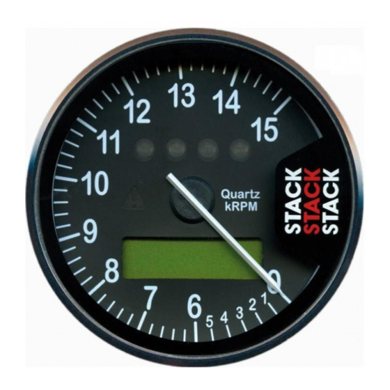
- Page 34 Operation ST700 Dash Display System Figure 12: ST700 Display features Normal mode is the normal operating condition of the ST700 Dash Display System. In this condition the system provides all available measurements and functions for the driver. Setup mode allows you to configure the ST700 Dash Display Sys- tem for your specific vehicle and driver requirements.
-
Page 35: Power-On The St700 Dash Display System
ST700 Dash Display System display: The dial illumination will turn on. The display backlighting will turn on. If you have configured the ST700 Dash Display System for a low inten- sity of backlight, it might be difficult to see the above illumination fea- tures. -
Page 36: Changing The Display Layers
ST700 Dash Display System Changing the display layers With the ST700 Dash Display System operating in its ‘normal’ mode, you will see a display similar to that shown in Figure 12. In the example shown, which features a '0-4-10500' dial face, the tachometer needle shows the engine is not running. - Page 37 ST700 Dash Display System Operation Press the Driver button and the Rotary control together to arm the ST700 Dash Display System for use in hillclimb and sprint operations, described on page 42. Press the Driver button to show Layer 2.
- Page 38 Display Layer 4 It is possible to disable this display layer in setup mode Layer 4 shows the minimum Corner Speed. This is the latest value trapped by the ST700 Dash Display System for the minimum speed reached while cornering. The Corner Speed feature is a useful tool to help drivers improve their performance through a specific turn.
- Page 39 Press the Driver button to return to Layer 1 and the beginning of the se- quence. Pop–up Display Layers The ST700 Dash Display System can supply information to the driver through several pop–up messages and alarms on the display as shown in Figure 13. The pop–up messages remain on display for a short, user–...
- Page 40 Operation ST700 Dash Display System Figure 13: Pop–up message examples Lap time (always enabled) M:SS.ss..or M:SS.s if time is longer than ten minutes Split time S1 and S2 (if enabled) Acceleration or deceleration time (if enabled) Standing quarter mile (if enabled)
-
Page 41: Lap And Split Times
ST700 Dash Display System Operation Lap and Split Times The lap timing feature of the ST700 Dash Display System allows you to measure the following: Total time to complete each lap Split times for up to two locations on the track Figure 14: Lap timing 1. - Page 42 The ST700 Dash Display System allows you to set split distances for S1 and S2 or for S1 by itself if you need only one split time per lap. You may set the split distances manually, or you may set them automatically as you drive the vehicle around the track.
-
Page 43: Manual Split Timing Setup
Manual Split Timing Setup To set the S1 and S2 split distances manually: 1. Enter the ST700 Dash Display System setup mode by pressing the rotary control for longer than two seconds. 2. When the display changes to allow memory review or setup, turn the control clockwise until it shows ‘Performance Timers’. - Page 44 Operation ST700 Dash Display System ting in larger steps if you hold the Driver button while you make this adjustment. Release the controls to set the Split 1 distance at the displayed value, which should be the distance from the lap refer- ence point.
-
Page 45: Automatic Split Timing Setup
Automatic Split Timing Setup To set the S1 and S2 split distances automatically: 1. Enter the ST700 Dash Display System setup mode by pressing the rotary control for longer than two seconds. 2. When the display changes to allow memory review or setup, turn the control clockwise until it shows ‘Performance Timers’. -
Page 46: Hillclimb And Sprint Operation
Hillclimb and Sprint Operation To remove the requirement for a beacon at the start line, your ST700 Dash Display System has an ‘arming’ feature. This allows you to set the ST700 Dash Display System so that it starts timing from the instant when the wheels begin to move. -
Page 47: Memory And Setup
ST700 Dash Display System. The diagram on the right shows the System Setup and the Memory review menus, which you may enter from the Run mode. The ST700 Dash Display System begins to operate in the Run mode after power–on. -
Page 48: Memory Review Features
Press and turn the rotary control to cycle through the lap memory, turn- ing the control anticlockwise to review earlier laps. The ST700 Dash Dis- play System can record lap and split times for up to 75 laps before the... - Page 49 You may set a start speed that is higher than the end speed to use the ST700 Dash Display System as a deceleration timer. If you press and hold the Driver button, the display shows the shortest acceleration or deceleration time recorded since you last reset the peak values.
- Page 50 Memory and SetupST700 Dash Display System starts to move. This information also appears in a pop–up message for the driver. Follow the instructions on page 49 to enable or disable the pop-up message. Reset peaks— Press and hold the rotary control for longer than one second to reset all the peak values.
-
Page 51: Setup Mode
ST700 Dash Display SystemMemory and Setup Setup mode In the Setup mode, if you press the Driver button as you press and turn the rotary control, you will adjust some of the settings in larger steps. Enter the Memory Review and System Setup mode as described on page 43. - Page 52 Set the speed in the same units used to display speed measurements—MPH or km/h. The ST700 Dash Display System will measure the time that it takes for the vehicle to accelerate or decelerate through the set speed...
- Page 53 ST700 Dash Display SystemMemory and Setup range. This information will be available in the memory review dis- play, described on page 45. It will also appear in a pop–up message if you have selected this function as described below. Turn the rotary control clockwise to show the current status of the acceleration timing pop–up.
- Page 54 Memory and SetupST700 Dash Display System ups. If you set the pop–up time to 99, pop–ups will remain on view until the Driver button is pressed. Turn the rotary control clockwise and then press it to return the dis- play to show ‘Popup Time’. Turn the rotary control clockwise again and then press it to return the display to show ‘Performance Timers’.
- Page 55 ST700 Dash Display SystemMemory and Setup Figure 15: Shift light sequence as engine speed increases Sequential Seq–bar Seq–blink Disabled—The display unit will not show the shift lights as the en- gine speed changes. Single —All four shift lights illuminate together when the engine speed reaches the set point for shift light 4 (the right–hand shift...
- Page 56 Note that the ST700 Dash Display System always maintains the correct sequence so that the shift lights illuminate from left to right as the engine speed increases.
- Page 57 ST700 Dash Display SystemMemory and Setup Channel settings—Press the rotary control briefly when the display shows ‘Channel Settings’ to setup the input channels to the ST700 Dash Display System. Press and turn the control to move among the channel settings sub-menus.
- Page 58 Refer to page 21 for instructions to install the wheel speed sensor. Meas units—Press and turn the control to set the ST700 Dash Dis- play System to measure in metric units or in imperial units. This set-...
- Page 59 Accel limit—Press and turn the rotary control to adjust the accelera- tion limit setting, which prevents the ST700 Dash Display System re- sponding to apparent extremes of acceleration caused, for example, by wheel spin. If wheel spin occurs on the wheel that has the wheel speed sensor, the speed reading from the sensor will step almost in- stantaneously to a much higher level.
- Page 60 MPH and miles or Km/h and kilometres for the displays of speed and odometer distance. Sensor Input 1 and Sensor Input 2—The ST700 Dash Display Sys- tem can display measurements made by up to two Stack sensors fit- ted to the vehicle. The information from these sensors appears on one of the display layers (see page 34).
- Page 61 You will disable the lap masking feature if you set the value to zero. The infrared lap timing system supplied by Stack uses a coded infra- red frequency that is common to all Stack lap timing systems. This feature allows users of Stack systems to share a common beacon at each circuit, and ensures that the ST700 Dash Display System will not be triggered by other manufacturers’...
- Page 62 Memory and SetupST700 Dash Display System It is important that you are aware that your beacon can be picked up by other Stack systems and can affect their lap times if you set up your beacon mid–session. Therefore, for the convenience and out of re- spect to other users, you should not set up your beacon when cars are running.
- Page 63 ST700 Dash Display SystemMemory and Setup turn the control to adjust the contrast setting in the range 0 to 31. Settings at either extreme of this range will be difficult to see. Exper- iment with the control to find the ideal setting.
-
Page 64: Testing
1. Switch on the vehicle ignition and check that the ST700 Dash Dis- play System initialises correctly as described on page 31. 2. Start the engine and let it warm at idling speed. Check that the tachometer display shows the correct reading for the engine idling speed. - Page 65 ST700 Dash Display System Testing Table 6: Time to cover measured distances at various speeds Speed Speed Time (secs) Time (secs) (MPH) (km/h) 1 mile 1000 metres 48.28 74.56 37.28 96.56 64.37 55.93 43.49 82.78 51.43 80.47 44.74 55.92 64.38 96.56...
-
Page 66: Maintenance
ST700 Dash Display System MAINTENANCE The ST700 Dash Display System is a fully sealed unit that has no wear- ing or consumable parts. The unit requires no maintenance after instal- lation. You will break the seals essential to keep the instrument waterproof and invalidate the product warranty if you remove the rear cover of the ST700 Dash Display System instrument. - Page 67 ST700 Dash Display System Maintenance The power lead is labelled B+ and B–. The battery positive lead B+ is on pin 1, and the battery negative B– is on pin 2 of the 8–way con- nector. Display is dead There is no backlight. Nothing appears on the display. The blue dial lights are on but appear dim.
- Page 68 Maintenance ST700 Dash Display System Display and dial show fixed high values Driver button (peaks) faulty Renew the Driver button. Disconnect the Driver button. If values return to normal, renew the button. Faulty switch wiring Check the switch wiring. Check wiring for a short between pin 8 and pin 2 (B–) of the 8–way connector.
- Page 69 ST700 Dash Display System Maintenance Rotary Control button: ‘Enter Setup Mode’ does not work. Rotary Control faulty Renew the Rotary Control Disconnect the Rotary Control and short together Pins 3 and 4 on the connector ‘RC’ for more than 2 seconds. If the display changes, re- new the Rotary Control.
- Page 70 Maintenance ST700 Dash Display System Disconnect the receiver and short together pins 1 and 4 on the ‘LapT’ connector. If the display changes, renew the receiver after checking its wiring. Trackside transmitter signal swamped by an adjacent transmitter. Move the transmitters so that they are at least 4 metres apart.
- Page 71 ST700 Dash Display System Maintenance Extra laps displayed. Lap times are too short. More than one transmitter around the circuit Remove all but one transmitter from the circuit. Increase the Lap Masking period. Display values and messages unclear or unreadable (poor contrast)
- Page 72 Maintenance ST700 Dash Display System Reconfigure the system to the correct number of pulses per revolution. Ignition systems may use multiple coils where each additional coil gives proportionately fewer pulses per revolution. Tachometer reading erratic, pointer jumps high or low...
- Page 73 ST700 Dash Display System Maintenance Check for a more suitable connection point, such as the coil negative signal. ECU or ignition system output requires a ‘pull up’ resistor to be fit- Fit a 1k0 ohm (1000 ohms) resistor from the ECU/ignition to Tacho lead, to...
- Page 74 Maintenance ST700 Dash Display System Rotate the wheel by hand and check that the sensor indicator lights up as each target passes the sensor Incorrect sensor gap (too far or too close) Check that the gap is approximately 1mm ± 0.5mm.
- Page 75 ST700 Dash Display System Maintenance ST700 Dash Display System wiring is too close to the HT leads and/ or injector leads, or the HT leads are tied to isolated metal work to which the system wiring is also tied. Run wiring away from HT leads and injector leads Recommended minimum spacing is 75mm (3.0 inches)
-
Page 76: Specification
Maintenance ST700 Dash Display System Specification Physical and environmental Size Front of dash 88mm Ø × 8mm (3.5” Ø × 0.3”) Behind dash 80mm Ø × 68mm (3.15” Ø × 2.7”) Overall 88mm Ø × 76mm (3.5” Ø × 3.0”) - Page 77 ST700 Dash Display System Maintenance Performance Engine speed Accuracy ±0.4% (non–linear dials) ±0.6% (linear dials) Range 400 to 32000 RPM Cylinders 1 to 16 (4–stroke)—1 to 8 (2–stroke) Input Coil negative, Magneto or ECU Tacho pulse output Max input frequency...
- Page 78 Maintenance ST700 Dash Display System Split time accuracy ±0.1s ±1 digit Laptime memory 75 laps of 1 × lap + 2 × split times Acceleration timer accuracy ±0.1s ±1 digit Quarter mile timer accuracy ±0.1s ±1 digit Corner speed accuracy ±0.25% ±1 digit...
-
Page 79: Contact Details
ST700 Dash Display System Maintenance Contact details The contact details for Stack are: UK and International USA and North America Stack Limited Stack Inc. Wedgwood Road 3545A Cove Creek Court Bicester Cumming Oxfordshire OX 26 4UL Atlanta Georgia GA 30040... - Page 80 Maintenance ST700 Dash Display System Figure 16: Wiring diagram—8–way harness...
- Page 81 ST700 Dash Display System Maintenance Figure 17: Wiring diagram—6–way harness © Stack...
- Page 82 Maintenance ST700 Dash Display System...
-
Page 83: Index
ST700 Dash Display System Index Index cylinders 53 Numerics deceleration limit 55 2–stroke engines 53 deceleration timing 48 demonstration mode 71 display contrast 58 acceleration limit 55 display illumination 29 acceleration timer 45 distance timing peaks 45 pop–up 49 acceleration timing distance units 56 pop–up 49... - Page 84 Index ST700 Dash Display System installation 8 split times 39 display unit 8 engine speed measurement odometer 32 infrared beacon 18 reset 32 lap timing button 20 odometer units 56 lap timing sensor 16 operating modes 30 power 27 pressure sensors 23...
- Page 85 ST700 Dash Display System Index performance timers 47 shift light 50 speed display 32 speed units 56 – split timing 37 manual setup 39 memory review mode 39 sprint 42 standing quarter mile 45 system setup See setup mode temperature sensor 25 two–stroke engines 53...
- Page 86 Index ST700 Dash Display System...
- Page 88 Published by Stack Limited Wedgwood Road Bicester Oxfordshire OX26 4UL England...
Need help?
Do you have a question about the ST700 and is the answer not in the manual?
Questions and answers