Table of Contents
Advertisement
Advertisement
Table of Contents

Related Manuals for Bentel Security BGS-220

Summary of Contents for Bentel Security BGS-220
- Page 1 220 Series Universal Cellular Communicator Installation manual...
- Page 2 Parts Parts 20 Electronic board locator pins Cover 21 JP2 current draw limiter jumper (versions with housing Base only): see “Description of jumpers” on page 8 Indicator lights (LED) 22 Battery connector: versions with housing only Closing screw (parked position) 23 ANT5-02 adapter cable Base mounting holes (4) 24 Adapter cable nut...
- Page 3 Figure 2 – Identification of parts: a) ANT5-02, GSM antenna with 2 m cable and SMA connector (optional); b) version with housing; c) kit version. 220 Series...
-
Page 4: Table Of Contents
The above mentioned 220 series is been designed and made to the highest standards of quality and performance. The manufacturer recommends that the installed system should be completely tested at least once a month. Bentel Security shall not be responsible for damage arising from improper installation or maintenance by unauthorized personnel. -
Page 5: Introduction
Quad-Band GPRS (HSPA Dual-Band) to Sur-Gard System I, II, III, IV and 5 receivers. The following versions are available. BGS-220: communicator board with 2G module in plastic housing. B3G-220: communicator board with 900/1800 MHz 3G module in plastic housing. -
Page 6: General Specifications
6 terminals, programmable as Open-Collector outputs or input lines. Protection against overvoltage on the phone line. 2G Quad band (BGS-220 and BGS-220K) or 3G, Dual Band (B3G-220/EU and B3G-220K/EU) communicator. Integrated antenna: versions with housing only. -
Page 7: Technical Specifications
When the communicator is powered by the battery, ONLY communicator events are transmitted. The primary power and (optional) battery voltages are supervised. The power supply for communicator models BGS-220 and B3G-220/EU must be SELV, with power limited to 1 A. BGS-220K... -
Page 8: Identification Of Parts
Interface type between SPT (Supervised Premises Transceiver) Proprietary interface and AS (Alarm System) ATS (Alarm Transmission System) SINGLE PATH Alarm Transmission System performance SP4 for digital messages SP2 for vocal/text messages Average transmission time D3 (20 s) D2 (60 s) Maximum transmission time M3 (60 s) M2 (120 s) -
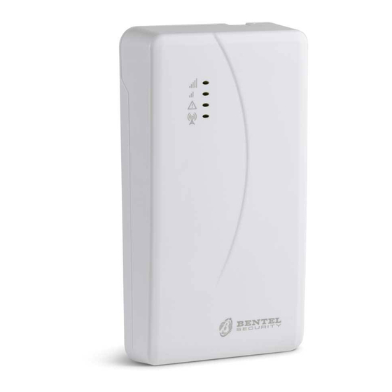
Page 9: Description Of Indicator Lights
Description of indicator lights The communicator is equipped with indicator lights (LED) which report the following information. During initialisation, all LEDs light up for less than 1 second. During factory settings restore, LEDs are off while LEDs are on. Colour Name Description... - Page 10 Type of communication Slow flashing Slow flashing Initialisation: the LEDs flash until the communicator receives a GSM signal. Fast flashing SMS incoming: the LED flashes for a few seconds. Slow flashing Remote session: the LED may flash for a few seconds after the end of the session. Slow flashing Voice call: reports the communicator's voice call, NOT that of the panel to which it is connected, if any.
-
Page 11: Description Of Terminals
Description of terminals Terminals Description Ground: this terminal must be connected to the electrical system ground to protect the device against overvoltage on the telephone line and to satisfy safety requirements. Internal telephone line: these terminals must be connected to the panel or other communications terminal. External telephone line: these terminals may be connected to the PSTN line. -
Page 12: Installation
Installation Connect the power supply and telephone circuits after the communicator is mounted and connected to the building ground circuit. Before fitting or removing the SIM card, make sure the communicator is NOT powered up. The communicator shall be installed only by a QUALIFIED TECHNICIAN, indoors, in a safe, dry position, away from RF transmitting equipment. - Page 13 Figure 3 – Installing the kit communicator: A) metal housing; B) communicator board; C) panel motherboard; D) adhesive plastic mount; E) base of metal housing. 220 Series...
- Page 14 Installing the version with housing The version with housing must be mounted to a wall with screws and plugs (not included) as described below and shown in figure 4. Open the communicator: insert a flathead screwdriver into holes 33 and prise the cover off the base, than slide the cover upwards to separate it from the base completely.
- Page 15 Figure 4 – Installing the communicator with housing. The communicator complies with the EN 50136-2 standard and, for this reason, its access codes have to be set at the first power up, by means of the Console, in this way the communicator functionality will be enabled. If you do not need the compliance with the EN 50136-2 and like to start working without the Console, please proceed as follows.
- Page 16 Installing the antenna ANT5-02 The ANT5-02 has greater gain than the communicator's integrated antenna in the version with housing, and can be mounted indoors within 2 meters of the communicator, to improve GSM reception, as described below and shown in figure 5. ...
- Page 17 Installing the antenna ANT5-15 The ANT5-15 has greater gain than the communicator's integrated antenna in the version with housing, and can be mounted outdoors within 15 m of the communicator, to improve GSM reception. Refer to the installation instructions included with the ANT5-15 antenna. Tamper detection The version with housing of the communicator is equipped with a device which detects when the cover is opened and the communicator is removed from the wall (tampering).
-
Page 18: Connection Example
Connection example Incorrect connections may result in FTC fault or improper operation. Inspect wiring and ensure connections are correct before applying power. DO NOT route any wiring over circuit boards; maintain at least 1” (24.5 mm) separation. A minimum 1/4” (6.4 mm) separation must be maintained at all points between Power Limited wiring and all other Not-Power Limited wiring. -
Page 19: General Description
GENERAL DESCRIPTION The communicator can communicate with central stations and send both SMS and voice messages; it can also simulate a PSTN line in case of malfunction (phone line failure) or substitute of one completely in areas with GSM coverage in which PSTN calls are not available. -
Page 20: Access Levels
Access levels This paragraph describes how to access the communicators functions, according to EN50136 standard. If the EN50136 option is enabled (factory default; see “Options” on page 41), the communicator can handle all four levels of user access to its functions. The access levels are as follows. ... -
Page 21: Usb Connector Functions
USB connector functions The communicator has a USB A connector to enable it to work as a device, to connect it to a PC, or as host, to handle a USB key (see “Description of jumpers” on page 8). To connect the communicator to a PC, you need a USB cable with A connectors at each end (hub cable). The USB interface has the following characteristics. -
Page 22: Power Monitor
Power Monitor The device can be powered in the following ways: by the burglar alarm panel, equipped with a backup battery, in which case the communicator must operate at voltages in the range 10.7 to 27.6 V. by an external 12 V power supply, in which case the power supply must recharge the communicator's optional backup battery (8 hours of operation following primary power outage). -
Page 23: Internal Events
Internal events Along with the external events (panel events decoded with the Contact ID / SIA protocols on the simulated PSTN line), the communicator also recognises the following events. Event Description This occurs when terminal T1 is programmed as an input and the conditions for its Input 1 Event activation obtain (see “Inputs/Outputs”... - Page 24 Event Description Happens when tamper detection is enabled (see “Description of jumpers” on page 8) and Tamper Restore the communicator is closed again or mounted to the wall (versions with housing only). Happens when an action fails (voice call, SMS, digital message). FTC Fault Happens when the last action in the queue terminates successfully.
-
Page 25: Operating Principles
Operating Principles The communicator can choose its primary channel (the factory setting is PSTN). It supplies the line and ringtone voltage for incoming calls and decodes dial tones (DTMF). The simulated PSTN line provides a backup for the burglar alarm panel or other terminal should the main PSTN line fail. - Page 26 Contact ID/SIA transmission sequence on cellular data network If phone numbers (prefixes on the PTM page) have been entered on the Console, the communicator switches the calls to these numbers to the cellular data network. When an event occurs, the burglar alarm panel engages the phone line. ...
-
Page 27: Priority Handling
Priority handling The communicator can: forward panel voice messages via GSM; forward panel Contact ID messages on the GSM voice channel; send its own voice messages; send its own SMS; send its own digital messages (Contact ID/SIA) on the cellular data network; ... -
Page 28: Pay As You Go Balance Check
Pay as you go balance check If programmed on the Console (see “Pay As You Go Balance” on page 42), you can check your balance on the prepaid SIM card. Once enabled, the system can check the pay as you go balance in three ways: On the Console (Status page, only via PC-Link or USB connection). -
Page 29: Activating Outputs
Activating outputs The communicator has 6 terminals (T1, T2, T3, T4, T5 and T6) which can be programmed as Inputs or Open-Collector Outputs. The Open Collector outputs can be activated automatically (when certain programmed events occur) or remotely, by SMS or caller recognition using a preprogrammed number. - Page 30 Bistable outputs Open Collector outputs configured to be bistable may be activated in two ways: By sending an SMS consisting of the pound (#), the User Code, the Control String (Control String can not have initial blank spaces) and the characters =ON*, as follows: #User Code*Control String=ON* (example: #123456*HOMELIGHT=ON*) Using Caller ID: in this case, the output is activated without charge, since once the device has recognised the caller, it activates the output without accepting the call.
- Page 31 Caller ID The output is activated free of charge, since after it has recognised the caller, the device activates the output without answering the call. Monostable OC outputs return to standby after the programmed Monostable Time On. The Monostable Time On can be set from 1 second to 86400 seconds, with a 1 second resolution. The default User Code is 000000;...
-
Page 32: Sms Programming
SMS Programming In addition to the processes described in the paragraph “Remote output activation/deactivation” on page 29, it is also possible to carry out other remote procedures through the transmission of various SMS messages. Changing the user code The default user code is 000000; to change it, send an SMS message consisting of the characters #CUC followed by the current user code and the new user code between * characters, in accordance with the following formula: #CUC*User code*New user code* The device will send an SMS to confirm that the user code has changed. - Page 33 Pay as you go balance check To check your pay as you go balance with an SMS, you can either use the Console (see “Pay As You Go Balance” on page 42) or send an SMS composed of the characters #CCC followed by * and the user code, as follows: #CCC*User code* or #ICCC followed by * and the installer code, as follows: #ICCC*Installer code*...
- Page 34 Disabling the installer To disable the installer from working with the device, the user must send a SMS composed of #DSI followed by the User code as follows: #DSI*User code* The device will confirm with an SMS. The installer is disabled automatically 12 hours after being enabled. Disabling the installer also automatically disables the level 4 installer.
-
Page 35: Pc Programming
PC PROGRAMMING For the communicator to work properly, you must use a 32 kB or better SIM card. To program the system with a PC, you need a PC-Link cable (not included), connected between connector 15 of the communicator and a PC COM port, and the Console (Figure 7). - Page 36 Description of the menus File menu New Account: Creates a new account and assigns the factory settings to all parameters. Account Group Maintenance: groups several accounts into a group. Recent Files: selects an existing account. Exit: Exits the program. You will be prompted to save any changes made to the current installation. ...
- Page 37 Icons present on all programming pages. Clear all tags for this group. Export. Restore all options to default. Restore all options to original. Tag all for upload: select all page options for upload. Tag all for download: select all page options for download. The following pages are available in the programming section.
-
Page 38: Restore Factory Settings
Programming/Audio Import/Export Button opens a window with the following functions. Export Programming: click on this button to export the current settings from the Console to a USB key. Import Programming: click on this button to import a communicator's settings from a USB key to the Console; the settings may be those previously exported from a Console running on another PC, or from a communicator. -
Page 39: Phonebook
Phonebook You can save up to 32 phone numbers in this page. If the periodic pay as you go balance function has been programmed for the communicator's SIM card (see the Options page) the answering SMS is sent to phone number #1. ... - Page 40 CID/SIA Virtual IP Receiver PSTN/ Communication Effects Event Receiver on on GSM protocol Conversion GSM Path Path PSTN No effect Disabled No effect No effect The panel's voice and digital messages (SIA and CID) are forwarded to PSTN. PSTN SIA / Contact ID Enabled No effect No effect The panel's voice and digital messages are...
-
Page 41: Options
Options This page differs depending on the user's access level: normal user, installer, level 4 installer. User Authentication Installer Code Enabled: the normal user uses this option to enable the installer for programming the communicator. The installer need only be enabled if the EN50136 option is enabled. The installer is disabled automatically 12 hours after being enabled. - Page 42 Black List Enabled: if enabled, the communicator accepts ONLY calls from numbers whose White List option is enabled (see “Phonebook” on page 39). The Black List function COMBINED with Activate Output on Caller ID delays call refusal by a few seconds. The confirmation ring tone associated with Activate Output on Caller ID delays call refusal by a few seconds.
-
Page 43: Network Settings
Enquiry Interval: enter the interval within which the periodic SMS is to be sent with the balance information (if handled by the operator). The interval is composed of the following values: — Days, day of next send—select to send the next periodic SMS. The value runs from 0 to 364; —... -
Page 44: Inputs/Outputs
Inputs/Outputs This page is used for setting the input/output modes, the output activation events, their standby polarity (NC or NO), the reserved outputs, and the remote activation SMS strings for the reserved outputs. Input/output: double click on the input/output number to view the settings. ... - Page 45 Type: normally the outputs, when activated, remain so until a deactivation command is received (Bistable), at which point the output will revert to its standby status. If you wish the output to return to standby automatically after a set period of time, select the option Monostable and set this time in the option Monostable Time ON next to it.
-
Page 46: Communicator
Communicator This page configures the events transmitted by the communicator. SMS/Voice Calls Call Options Call All Numbers: select this option to call all numbers set for a given event. You can select: Voice Calls, CID: Over GSM, Voice Calls and CID: Over GSM and Disabled. If this option is not selected, the communicator terminates the cycle of calls as soon one of them terminates successfully. - Page 47 Voice Messages: select the voice messages to be sent in response to the event: you can select up to three voice messages per event (First Message, Second Message and Third Message); click on [...] to browse the list of messages; you can select a pre-recorded message (see Voice Messages) or record a new one, or open a .wav file on the PC.
- Page 48 Telephone Numbers: select the numbers to which the event is to send the digital message, when you have selected Channel Type, CID: Over GSM. When you select Channel Type, CID/SIA: over Data Network, the events are transmitted to the IP receivers indicated in the IP Receivers page.
-
Page 49: Ip Receivers
IP Receivers This page sets the options relating to the communicator's connection with Sur-Gard System IP receivers I, II, III, IV and 5. Given possible delays in transmission on the cellular data network, depending on the activity of the network operator, we recommend programming as high as possible the number of call attempts on the panel, and also setting a backup phone number which will send the alarms via GSM rather than cellular data network. -
Page 50: Voice Messages
Supervision Time 1: set the supervision time. Range: 60 to 65535 s, in 1 s steps. In order to ensure conformity with EN 50136-2 supervision must be enabled and the Supervision Time must be no more than 3 minutes. Receiver 2 The options for Receiver 2 are the same as those for Receiver 1, except for the differences described below. -
Page 51: Pstn/Ptm
PSTN/PTM This page relates to the PSTN line and the PTM function (Panel Transmission Monitoring). The PTM function enables the communicator to forward calls on the GSM channel if communications between the panel and the receiver on the PSTN line fail. ... -
Page 52: Event Log
Event Log The Event Log page displays the events logged by the communicator. The communicator can save up to 2048 events: when the buffer is full, each new event overwrites the oldest, which is thus lost. Each event indicates the date and time at which it occurred. Symbols on the Event Buffer bar Click on this icon to load the new events the next time a Global Upload or Communicate Tags is run. -
Page 53: Status
Status This page gives a range of information about the communicator, as indicated below. When you select the Status page, the Console automatically displays the Communicate Tags window to establish communications with the communicator; once it is, the Status page updates every 5 seconds Device Information The Device Details box shows information which may be requested by technical assistance. - Page 54 Call Incoming Call: orange—the communicator is receiving a call. Call In Progress: green—the communicator is engaged with a call. Outgoing Call: orange—the communicator is making a call. Radio Initializing: green—the radio is initialising. Passthrough: not supported. Receiver 1 ...
-
Page 55: Appendix
APPENDIX Conformity with EN 50136-2:2013 To be compliant with EN50136-2:2013, the communicator must be configured and connected to a burglary alarm panel in one of the two following ways (A and B) only: A) PSTN connection (the panel must monitor the receiver's response directly via PSTN) ... - Page 56 See the following tables. Communicator Panel T1: PSTN Fault output T2: No Cellular Network output T3: Interconnection Present LE Detection output T4: Tamper output Communicator Tamper input T5: GSM Fault output GSM Fault input T6: IP Receiver Communications Failure output IP Receiver Communications Failure input Table 13 –...
-
Page 57: Operations With The Usb Key
Operations with the USB key The USB can ONLY be used if the communicator is in USB Host mode (see “Description of jumpers” on page 8) and the EN50136 option is disabled (see “Options” on page 41). The USB key allows you to: ... -
Page 58: Exporting Settings
SSSSSSSS represents the communicator's serial number (8 hex digits), so that a single USB key can hold data for several different communicators: each communicator will read/write to its own folder. When a USB key is inserted into the communicator, the following procedure is executed: Firmware update, if a valid firmware is in folder B_FW;... -
Page 59: Importing Settings
If the EXPORT folder already has a settings file with index 999, exporting is not possible: the ACT LED will flash slowly and the event USB Programming Export Failed - System is logged to the event buffer. Importing settings This procedure imports settings from a USB key. Create the folder B_PROG on the USB key, if it is not already there. - Page 60 Exporting the Event Buffer This operation exports the communicator's event buffer to a CSV format text file (Comma Separated Value) on the USB key: the CVS file can be viewed with Excel and Noteblock. Create the folder B_LOG on the USB key, if it is not already there. Create a new text file in B_LOG and call it log.txt.
-
Page 61: Pass-Through
220 Series... - Page 62 Universal Cellular Communicator...
- Page 64 BENTEL SECURITY s.r.l. – Via Gabbiano, 22 – Z. Ind. S. Scolastica – Corropoli (TE) – Italy – tel.: +39 0861 839060 Fax: +39 0861 839065 – infobentelsecurity@tycoint.com – www.bentelsecurity.com ISTISBLEBGS220 1.0 231116 FM10...
Need help?
Do you have a question about the BGS-220 and is the answer not in the manual?
Questions and answers