Advertisement
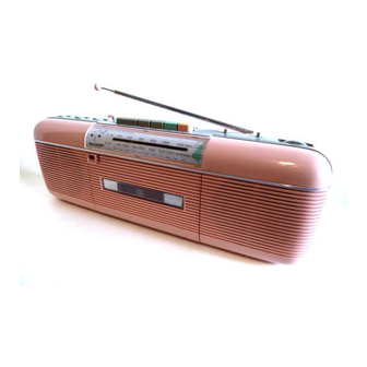
Photo: QT-502(W)
NAMES OF PARTS . . . . . . . . . . . . . . . . . . . . . . . . . . . . . . . . . . . . . . . . . . . . . .
DISASSEMBLY . . . . . . . . . . . . . . . . . . . . . . . . . . . . . . . . . . . . . . . . . . . . . . . . .
VOLTAGE SELECTION . . . . . . . . . . . . . . . . . . . . . . . . . . . . . . . . . . . . . . . . . . .
S T R I N G I N G O F D I A L C O R D . . . . . . . . . . . . . . . . . . . . . . . . . . . . . . . . . . . . . .
MECHANICAL
CIRCUIT ADJUSTMENT . . . . . . . . . . . . . . . . . . . . . . . . . . . . . . . . . . . . . . . .
SCHEMATIC
NOTES ON SCHEMATIC DIAGRAM. . . . . . . . . . . . . . . . . . . . . . . . . . . . . . . . . .
W I R I N G S I D E O F P.W.BOARD . . . . . . . . . . . . . . . . . . . . . . . . . . . . . . . . . .
E X P L O D E D VIEW............................................11,12
REPLACEMENT PARTS LIST . . . . . . . . . . . . . . . . . . . . . . . . . . . . . . . . . .
SERVICE MANUAL
ADJUSTMENT . . . . . . . . . . . . . . . . . . . . . . . . . . . . . . . . . . . . . .
DIAGRAM. . . . . . . . . . . . . . . . . . . . . . . . . . . . . . . . . . . . . . . . .
In the interests of user-safety the set should be restored to its
original condition and only parts identical to those pacified be
used.
Page
2
2
3
3
4
4
9
9, IO
13 - 16
Advertisement
Table of Contents

Related Manuals for Sharp QT-50Z


Summary of Contents for Sharp QT-50Z
- Page 1 SERVICE MANUAL Photo: QT-502(W) In the interests of user-safety the set should be restored to its original condition and only parts identical to those pacified be used. Page NAMES OF PARTS ..........DISASSEMBLY .
-
Page 2: Specifications
FOR A COMPLETE DESCRIPTION OF THE OPERATION OF THIS UNIT, PLEASE REFER TO THE OPERATlON MANUAL. GENERAL TAPE RECORDER Power source: Tape: Compact cassette tape 240 V, 50160 Hz Frequency range: 50 Hz - 10,000 Hz DC 9V (UM/SUM-2 or RI4 type Signal/noise ratio: 36 dB Input impedance:... - Page 3 This unit is provided with a carring belt, but it is not depicted in the following Figures. Caution on Disassembly Follow the below-mentioned notes when disassembling the unit and reassembling it, to keep its safety and excellent performance: 1. Take cassette tape out of the unit. 2.
-
Page 4: Mechanical Adjustment
1. Turn the drum fully in the direction A shown in Fig. 4-1 and stretch its cord over the parts in the numerical order. 2. The turn the tuning control shaft fully in the direction B shown in Fig. 4-l and fix its pointer as shown in Fig. 4-2. Figure 4-l ITEM USING JIG... - Page 5 Volume control: Maximum Balance controk Center Tone control: Center Function selector switch: Tape POSITION OF KNOB ITEM PLAYBACK AMP- Test tape SENSITIVITY Figure 5-l PLAYBACK AMPLIFIER SENSITIVITY AM LF/RF ADJUSTMENT 400 Hr. 30%. AM modulated D I A L AD REMARKS N C Y SElTlNG Figure 5-2 AM IF...
- Page 6 FM IF/RF ADJUSTMENT FM mono DIAL turn the core of T2 Figure 6-l FM IF counter-clockwise High before taking it out oi 1 0 . 7 MH frequency this bobbin. until no i ther improvement can be made. Lowest frequency Highest Figure 6-3 FM “S”...
- Page 7 MAIN NOTES ON SCHEMATIC DIAGRAM can be found on page 9. Figure 7 SCt-...
-
Page 9: Notes On Schematic Diagram
by Digital Multimeter between such a section and the Resistor: To differentiate the units of resistors, such symbol as K is chassis with no signal given. used: the symbol K means 1000 ohm and the resistor Marking except for ( without any symbol is ohm-type resistor. - Page 10 parts...
- Page 11 Figure 11 MECHANISM EXPLODED VIEW...
- Page 12 2 0 4 Figure 12 CABINET EXPLODED VIEW...
-
Page 13: Replacement Parts List
REPLACEMENT PARTS LIST To have your order filled promptly and correctly, please furnish the following information, 1. MODEL NUMBER 2. REF. NO. 3. PART NO. 4. DESCRIPTION Parts marked with “ 8” are important for maintaining the safety of the set. Be sure to replace these parts with specified ones for maintaining the safety and performance of the set. - Page 14 PART NO. DESCRIPTION CODE PART NO. DESCRIPTION CODE 4 7 pF, IOV Cl67 100 pF, IOV Cl 68 V C T Y P A I EX473M 0.047 pF, 25V. &20%, S C A A 2200 pF, 16V VCTYMFl HV472M 0.0047 /.LF, 50V. +20%, SC AA Cl 69 Cl 70 100 pF, 16V...
-
Page 15: Mechanical Parts
PART NO. REF. NO. DESCRIPTION CODE DESCRIPTION CODE PART NO. Lever, Playback Idler 3.3 kohms Idler. Playback RI 36 3.3 kohms Spring, Playback Idler 560 ohms Spacer, Playback Idler 1 kohm Gear, Fast Forward 1 kohm Flywheel Assembly 2.2 kohms Bracket, Flywheel 1 Mohm Bracket, Flywheel... -
Page 16: Cabinet Parts
Label, N.T.S. Bracket, Speaker Retaining AA Label, EGC Bracket, Belt Label, EP, for PX Frame Lebel, POP Nylon Band, 60mm Battery Screw. 3mm Dia. 45mm Writer and Editor: Engineering Administration Section of Audio Systems Group, Sharp Corp. Printed in Japan... - Page 17 Service Manual for QT-SOZ(W) In the interests of user-safety the set should be restored to its original condition and only parts identical to those specified be used. DIFFERENCE BETWEEN QT-50Z(W), QT-5OZ(BL) AND QT-50Z(L) REF. DESCRIPTION CABINET PARTS Front Cabinet Combined Assemblv...
Need help?
Do you have a question about the QT-50Z and is the answer not in the manual?
Questions and answers