
Related Manuals for Komfovent DOMEKT ReGO 400VE-B


Summary of Contents for Komfovent DOMEKT ReGO 400VE-B
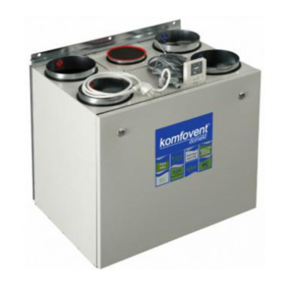
- Page 1 DOMEKT REGO 400VE(W)-B Series Air Handling Units Installation and Maintenance Service Manual...
-
Page 2: Table Of Contents
Content Safety Requirements .................. Transportation .................. Brief Description of the Unit .................. Installation .................. Maintenance ................Technical Information ................Ordering Key ................This symbol indicates that this product is not to be disposed of with your household waste, according to the WEEE Directive (2002/96/EC) and your national law. -
Page 3: Safety Requirements
Installation and Maintenance Service Manual Safety Requirements • To avoid accidents and/or unit damage, only a trained technician must carry out the connection. • The appropriate Personal Protective Equipment (PPE) attire is worn relative to the operation being carried out. •... - Page 4 Installation and Maintenance Service Manual Forklift truck or hand pallet truck can transport air handling unit as it is shown ( 2 a, b Pictures). Air handling unit transportation by forklift truck or hand pallet truck 2 b Picture 2 a Picture 2 a Unit is transported by hand pallet truck on a wooden pallet;...
-
Page 5: Brief Description Of The Unit
Installation and Maintenance Service Manual Brief Description of the Unit • The air handling units are intended for ventilation of small and medium-sized spaces (eg. single family houses, offices, etc.), having operating ambient temperature and relative humidity. The unit is intended to be in- stalled in the kitchen or other domestic premises. -
Page 6: Installation
Installation and Maintenance Service Manual Installation Unit Inspection Before installing the unit, inspection must be carried out. Unit has removable panels from its both sides (4 Picture). 4 Picture All internal unit components can be extracted from inspection side. After choosing desired inspection side, it is ne- cessary to check if rotary heat exchanger, electric heater and automatics box are positioned correctly. - Page 7 Installation and Maintenance Service Manual Afterwards electric heater may be extracted, turned round and put in by its other side (6 Picture). Then rotary heat exchanger and automatics box must be turned round being already disconnected from all connections and with unscrewed grounding wires (7 Picture).
- Page 8 Installation and Maintenance Service Manual Disconnect fans’ connections; pull out air temperature sensor together with a rubber plug. Loosen all wires fixed in the partitions with rubber gaskets and extract rotary heat exchanger (9 Picture). pull disconnect 9 Picture While unit casing is disassembled, all protective gaskets from the unit back side must be removed on its front one (10 Picture).
- Page 9 Installation and Maintenance Service Manual Insert rotor by its correct side; put on protective gaskets to their places (12 Picture). When changing inspection sides, be sure fans’ connecting plugs are not counter- changed. Fans are connected by the same connections. In case if unit is right-hand side, fans wires are crossed over in rotary heat exchanger’s electronics place.
- Page 10 Installation and Maintenance Service Manual The place for the unit should be selected with allowance for minimum access to the unit for maintenance and service inspection. The minimum free space in front of the inspection panel should be not less than 600 mm. It is recommended to install the air handling unit in a separate room (15 Picture).
-
Page 11: Maintenance
Maintenance It is recommended to carry out routine maintenance of the air handling unit KOMFOVENT DOMEKT REGO 400VE(W) 3 – 4 times per year. Extracting unit elements (see 17 Picture). Cables must be disconnected when extracting electric heater and rotary heat exchanger. - Page 12 Installation and Maintenance Service Manual Rotor cleaning 18 Picture 2. Fans check (once per year). Polluted fans decrease efficiency. Before performing any inspection work, check whether the unit is switched off from the electric power supply. Fans should be carefully cleaned with textile or soft brush. Do not use water. Do not break balance. Check if fan freely rotates and is not mechanically damaged, if impeller does not touch suction nozzles, fan does not spread noise and mounting bolts are screwed.
-
Page 13: Technical Information
Technical Information Specifications REGO 400VE(W) Dimensions AC VE/VW EC VE/VW Nominal air flow Unit weight Heater capacity 1,0 / 1,2 1,0 / 1,2 Fans input power 2x137 2x70 Supply voltage V / Hz ~230 / 50 /1 phase ~230 / 50 /1 phase Maximal operating current 5,75 / 1,41 5,15 / 0,76... - Page 14 Installation and Maintenance Service Manual REGO 400VE(W*)-B-AC Performance Air volume, m REGO 400VE(W*)-B-EC Performance Air volume, m * Correction factor for REGO 400VW - 15Pa We reserve the right to make changes without prior notice.
-
Page 15: Ordering Key
Installation and Maintenance Service Manual Scheme 160(4x) Ordering Key REGO – 400 – V E(W) – B AC / EC – C4 – F Filter class (F5 or F7) Controller type: C4 Motor type: AC – alternating current, EC – electronically commutated By - pass Air heater: W-water, E-electric Version: vertical... - Page 16 UAB AMALVA Ozo str. 10, LT–08200 VILNIUS, LITHUANIA e-mail info@amalva.lt www.amalva.com www.komfovent.com 2012...
Need help?
Do you have a question about the DOMEKT ReGO 400VE-B and is the answer not in the manual?
Questions and answers