Table of Contents
Advertisement
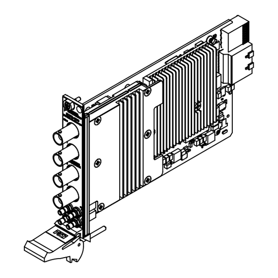
GETTING STARTED GUIDE
NI PXI/PXIe/PCI-5122
14-Bit, 100 MS/s PXI Oscilloscope
Note
Before you begin, install and configure your chassis and controller.
This document explains how to install, configure, and test the PXI/PXIe/PCI-5122.
To access PXI/PXIe/PCI-5122 documentation, including the NI PXI/PXIe/PCI-5122 Getting
Started Guide, go to Start»All Programs»National Instruments»NI-SCOPE»
Documentation.
Caution
use it in a manner not described in this document.
Contents
Electromagnetic Compatibility Guidelines...............................................................................2
Verifying the System Requirements......................................................................................... 2
Unpacking the Kit..................................................................................................................... 2
Kit Contents...................................................................................................................... 3
Preparing the Environment....................................................................................................... 3
PXI Modules..................................................................................................................... 3
PXI Express Modules....................................................................................................... 4
PCI Modules..................................................................................................................... 4
Installing the Software.............................................................................................................. 4
Installing the PXI/PXIe-5122................................................................................................... 5
Installing the PCI-5122............................................................................................................. 6
Front Panel Connectors and Indicators..................................................................................... 8
Configuring the PXI/PXIe/PCI-5122 in MAX......................................................................... 9
Programming the PXI/PXIe/PCI-5122................................................................................... 10
NI-SCOPE Examples......................................................................................................11
Making a Measurement...........................................................................................................11
Making a Measurement with NI-SCOPE SFP................................................................11
Making a Measurement with LabVIEW.........................................................................11
Setting Up SMC-Based Devices for Synchronization............................................................ 12
PXI and PXI Express Modules....................................................................................... 12
PCI Modules................................................................................................................... 12
Troubleshooting...................................................................................................................... 12
Why Is the ACCESS LED Off When the Chassis Is On?.............................................. 12
What Should I Do if the PXI/PXIe/PCI-5122 Doesn't Appear in MAX?...................... 13
You can impair the protection provided by the PXI/PXIe/PCI-5122 if you
Advertisement
Table of Contents

Related Manuals for NI PXI-5122


Summary of Contents for NI PXI-5122
-
Page 1: Table Of Contents
Note Before you begin, install and configure your chassis and controller. This document explains how to install, configure, and test the PXI/PXIe/PCI-5122. To access PXI/PXIe/PCI-5122 documentation, including the NI PXI/PXIe/PCI-5122 Getting Started Guide, go to Start»All Programs»National Instruments»NI-SCOPE» Documentation. Caution You can impair the protection provided by the PXI/PXIe/PCI-5122 if you use it in a manner not described in this document. -
Page 2: Electromagnetic Compatibility Guidelines
Do not install a device if it appears damaged in any way. Unpack any other items and documentation from the kit. Store the device in the antistatic package when the device is not in use. 2 | ni.com | NI PXI/PXIe/PCI-5122 Getting Started Guide... -
Page 3: Kit Contents
IEC 60068-2-1 and IEC 60068-2-2.) Relative humidity range 10% to 90%, noncondensing (Tested in accordance with IEC 60068-2-56.) Maximum altitude 2,000 m (at 25 °C ambient temperature) Pollution Degree Indoor use only. NI PXI/PXIe/PCI-5122 Getting Started Guide | © National Instruments | 3... -
Page 4: Pxi Express Modules
For complete specifications, refer to specifications document for your device at ni.com/ manuals. Installing the Software You must be an Administrator to install NI software on your computer. ™ ™ Install an ADE, such as LabVIEW or LabWindows /CVI Insert the driver software media into your computer. -
Page 5: Installing The Pxi/Pxie-5122
Ensure that the ejector handle is in the downward (unlatched) position. Place the module edges into the module guides at the top and bottom of the chassis. Slide the module into the slot until it is fully inserted. NI PXI/PXIe/PCI-5122 Getting Started Guide | © National Instruments | 5... -
Page 6: Installing The Pci-5122
Locate a compatible slot and remove the corresponding slot cover on the computer back panel. PCI-5122 modules can only be inserted into PCI slots. To maximize airflow and extend the life of the PCI device, leave any adjacent PCI slots empty. 6 | ni.com | NI PXI/PXIe/PCI-5122 Getting Started Guide... - Page 7 For SMC-based devices, spread-spectrum clocking varies the clock signal to spread the timing clock signal over a small frequency range. Disabling spread-spectrum clocking may affect the accuracy of device specifications. NI PXI/PXIe/PCI-5122 Getting Started Guide | © National Instruments | 7...
-
Page 8: Front Panel Connectors And Indicators
CLK OUT Sample clock output and Reference clock output SMB jack AUX I/O PFI 0 and PFI 1 lines for digital trigger input/output 9-pin mini-circular DIN and probe compensation (PFI 1 only). 8 | ni.com | NI PXI/PXIe/PCI-5122 Getting Started Guide... -
Page 9: Configuring The Pxi/Pxie/Pci-5122 In Max
5. Reserved Configuring the PXI/PXIe/PCI-5122 in MAX Use Measurement & Automation Explorer (MAX) to configure your NI hardware. MAX informs other programs about which devices reside in the system and how they are configured. MAX is automatically installed with NI-SCOPE. -
Page 10: Programming The Pxi/Pxie/Pci-5122
What Should I Do if the Module Fails the Self-Test? on page 13 Programming the PXI/PXIe/PCI-5122 You can acquire data interactively using the NI-SCOPE SFP, or you can use the NI-SCOPE instrument driver to program your device in the supported ADE of your choice. Table 3. PXI/PXIe/PCI-5122 Programming Options... -
Page 11: Ni-Scope Examples
Examples demonstrate the functionality of the device and serve as programming models and building blocks for your own applications. The NI Example Finder is a utility available for some ADEs that organizes examples into categories and allows you to easily browse and search installed examples. You can see descriptions and compatible hardware models for each example, or see all the examples compatible with one particular hardware model. -
Page 12: Setting Up Smc-Based Devices For Synchronization
In the dialog box that opens, select NI-RTSI Cable. Click Finish. In the MAX configuration pane, right-click the NI-RTSI cable, select Add Device to NI- RTSI Cable, and select the device you want to add. For more information about connecting PCI devices, refer to NI High-Speed Digitizers Help»Programming»Reference»NI-TClk Synchronization Help. -
Page 13: What Should I Do If The Pxi/Pxie/Pci-5122 Doesn't Appear In Max
Verify that the module appears in MAX. Reset the module in MAX and perform a self-test. If the ACCESS LED still fails to light and failures continue, contact NI technical support or visit ni.com/support. Related Information Installing the PXI/PXIe-5122... -
Page 14: Thermal Shutdown Error
For more information about cooling the device, refer to the Maintain Forced-Air Cooling Note to Users included in your kit. Related Information Installing the PXI/PXIe-5122 on page 5 Installing the PCI-5122 on page 6 14 | ni.com | NI PXI/PXIe/PCI-5122 Getting Started Guide... -
Page 15: Where To Go Next
Located using the NI Example Finder Worldwide Support and Services The NI website is your complete resource for technical support. At ni.com/support, you have access to everything from troubleshooting and application development self-help resources to email and phone assistance from NI Application Engineers. - Page 16 National Instruments Patent Notice at . You can find patents.txt ni.com/patents information about end-user license agreements (EULAs) and third-party legal notices in the readme file for your NI product. Refer to the Export Compliance Information at for the NI global trade ni.com/legal/export-compliance compliance policy and how to obtain relevant HTS codes, ECCNs, and other import/export data.
Need help?
Do you have a question about the PXI-5122 and is the answer not in the manual?
Questions and answers