Table of Contents
Advertisement
Quick Links
Please dispose of packaging for the product in a responsible
manner. It is suitable for recycling. Help to protect the
environment, take the packaging to the local amenity tip
and place into the appropriate recycling bin.
Never dispose of electrical equipment or batteries in with
your domestic waste. If your supplier offers a disposal facili-
ty please use it or alternatively use a recognised re-cycling
agent. This will allow the recycling of raw materials and help
protect the environment.
FOR HELP OR ADVICE ON THIS PRODUCT PLEASE CONTACT YOUR DISTRIBUTOR,
OR SIP DIRECTLY ON:
TEL: 01509500400
EMAIL: sales@sip-group.com or technical@sip-group.com
www.sip-group.com
Ref: 050716
60
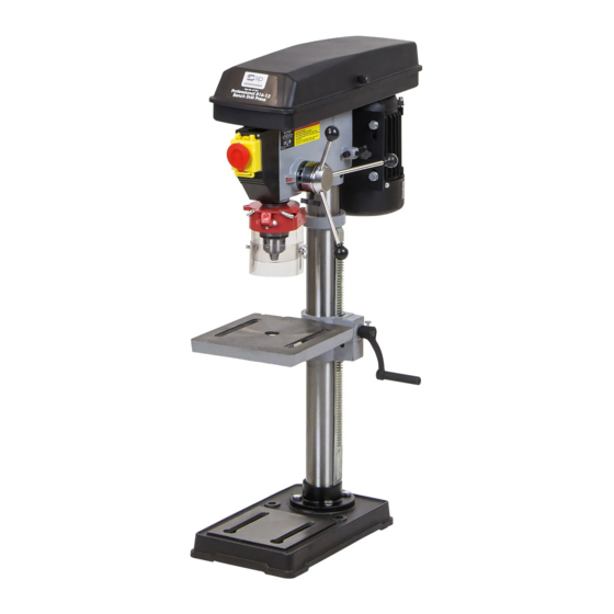
Pillar Drill Range
01700 - 01708
Please read and fully understand the instructions in this manual
before operation. Keep this manual safe for future reference.
1
Advertisement
Table of Contents

Related Manuals for SIP B13-13


Summary of Contents for SIP B13-13
- Page 1 This will allow the recycling of raw materials and help protect the environment. FOR HELP OR ADVICE ON THIS PRODUCT PLEASE CONTACT YOUR DISTRIBUTOR, OR SIP DIRECTLY ON: TEL: 01509500400 EMAIL: sales@sip-group.com or technical@sip-group.com 01700 - 01708 www.sip-group.com...
- Page 2 Machinery Directive 2014/30/EU EMC Directive 2011/65/EU RoHS Directive And the following harmonised standard(s), including: EN 60204-1:2006+A1:2009 EN 12717:2001+A1:2009 EN 55014-1:2006+A2:2011 EN 55014-1:1997+A2:2008 EN 61000-3-2:2014 EN 61000-3-3:2013 Signed: Mr P. Ippaso - Managing Director - SIP (Industrial Products) Ltd Date: 16/05/2016.
-
Page 3: Table Of Contents
Parts List - 01706 EN 61000-3-3:2008 Exploded Drawing - 01707 EN 61000-3-11:2000 Parts List - 01707 Exploded Drawing - 01708 Signed: Parts List - 01708 Declaration of Conformity Mr P. Ippaso - Managing Director - SIP (Industrial Products) Ltd Date: 16/05/2016. - Page 4 SAFETY SYMBOLS USED THROUGHOUT THIS MANUAL NOTES Danger / Caution: Indicates risk of personal injury and/or the possibility of damage. Warning: Risk of electrical injury or damage! Note: Supplementary information. SAFETY INSTRUCTIONS IMPORTANT: Please read the following instructions carefully, failure to do so could lead to serious personal injury and / or damage to the drill.
-
Page 5: Parts
Always keep the hand grip/s on the drill clean, dry and free of oil and grease. USE ONLY RECOMMENDED ACCESSORIES: Consult this user manual, your distributor or SIP directly for recommended accessories. Follow the instructions that accompany the... -
Page 6: Parts
SAFETY INSTRUCTIONS….cont PARTS LIST - 01708….cont accessories. The use of improper accessories may cause hazards and will invalidate Ref. No. Description SIP Part No. Ref. No. Description SIP Part No. any warranty you may have. Nut M5 WD01-00697 WD02-00380 REMOVE ADJUSTING KEYS AND WRENCHES: Form a habit of checking to see that keys... -
Page 7: Parts
PARTS LIST - 01708 SAFETY INSTRUCTIONS….cont Ref. No. Description SIP Part No. Ref. No. Description SIP Part No. Remove the key from the chuck after adjustment. Use only the chuck key provided by the manufacturer or a duplicate of it. -
Page 8: Exploded
TECHNICAL SPECIFICATIONS EXPLODED DRAWING - 01708 Part number 01700 01701 01702 Model B13-13 B16-12 B16-16 Input Voltage 230v ~ 50hz 230v ~ 50hz 230v ~ 50hz Power 350 w 375 w 375 w Speed Range 620-2620 rpm 300-2550 rpm 180-2770 rpm... -
Page 9: Parts
PARTS LIST - 01707….cont TECHNICAL SPECIFICATIONS….cont Ref. No. Description SIP Part No. Ref. No. Description SIP Part No. Washer M6 WD01-00702 Screw (M6 x 12) WD02-00381 Spring washer M6 WD01-00707 Screw (10 x25) WD02-00382 Nut M6 WD01-00710 Casting WD02-00383 Cam assembly... -
Page 10: Parts
TECHNICAL SPECIFICATIONS….cont PARTS LIST - 01707 Ref. No. Description SIP Part No. Ref. No. Description SIP Part No. Base WD02-00329 Connection WD02-00354 Column flange WD02-00330 Pinion shaft WD02-00355 Spring washer M10 WD01-00795 Indicator WD01-00897 Bolt (M10 x 35) WD02-00331 Screw... -
Page 11: Exploded
Connecting to the power supply: These SIP drills (01700-01707) are fitted with a standard 230v ~ 13 amp type plug. Be- fore using the drill, inspect the mains lead and plug to ensure that neither are dam- aged. If any damage is visible have the drill inspected / repaired by a suitably quali- fied person. -
Page 12: Parts
Connecting to the power supply: Tension spring cover WD02-00314 109. Lamp socket WD01-00837 The SIP 01708 F32-20 pillar drill requires 400v 50hz supply. Before each use, inspect the Nut M12 WD01-00821 110. Chuck guard 65mm 07664 mains lead and plug (where applicable) to ensure that neither are damaged. If any... -
Page 13: Parts
WD01-00706 Label WD02-00292 Washer M5 WD01-00881 These SIP pillar drills are covered by a 12 month parts and labour warranty covering Knob WD01-00867 Spring washer M5 WD01-00882 failure due to manufacturers defects. This does not cover failure due to misuse or op-... -
Page 14: Exploded
GETTING TO KNOW YOUR DRILL EXPLODED DRAWING - 01706 01700 Ref. No. Description Ref. No. Description Pulley Cover Belt Tension Lock Motor Column Support NVR On/Off Switch Base Chuck Guard Main Drill Head Chuck Column Feed Handle Column Support Bolts Table Depth Stop Table Support Collar... - Page 15 PARTS LIST - 01705….cont GETTING TO KNOW YOUR DRILL….cont 01701 - 01708 Ref. No. Description SIP Part No. Ref. No. Description SIP Part No. Circlip WD01-00713 Bearing 6006 WD01-00900 Spindle shaft WD01-00888 Washer WD01-00901 Bearing 6005 WD01-00889 Arbor MT2 66633...
- Page 16 ASSEMBLY INSTRUCTIONS PARTS LIST - 01705 FIT THE COLUMN TO THE BASE - BENCH DRILL Ref. No. Description SIP Part No. Ref. No. Description SIP Part No. Base WD01-00863 Washer M8 WD01-00672 Column flange WD01-00864 Motor plate WD01-00874 Spring washer M10...
-
Page 17: Exploded
EXPLODED DRAWING - 01705 ASSEMBLY INSTRUCTIONS….cont FIT THE TABLE - 01700 Ensure that the table support lock is loose. Slide the table support over the column until it is in position. Secure in place by tightening the table lock towards the rear of the table support. FIT THE RACK &... - Page 18 ASSEMBLY INSTRUCTIONS….cont PARTS LIST - 01704….cont Ref. No. Description SIP Part No. Ref. No. Description SIP Part No. Screw (M5 x 16) WD01-00838 Worm gear WD01-00848 Grub Screw Mains lead clamp WD01-00700 Table support WD01-00849 Secure the table support arm in place by fitting...
- Page 19 PARTS LIST - 01704 ASSEMBLY INSTRUCTIONS….cont Ref. No. Description SIP Part No. Ref. No. Description SIP Part No. Base WD01-00793 Washer M8 WD01-00672 Column flange WD01-00794 Motor plate WD01-00820 Spring washer M10 WD01-00795 Nut M12 WD01-00821 Carefully raise the head above the column.
-
Page 20: Exploded
ASSEMBLY INSTRUCTIONS….cont EXPLODED DRAWING - 01704 Fit the cover and secure with the screw (015). FIT THE ARBOR & CHUCK Prior to fitting the chuck / arbor; Fit the chuck guard: Slide the chuck guard over the spindle collar ensuring that the ‘open’... - Page 21 PARTS LIST - 01703….cont OPERATING INSTRUCTIONS Ref. No. Description SIP Part No. Ref. No. Description SIP Part No. Danger: Before making any changes or adjustments, ensure that the drill is Spindle shaft WD01-00888 Washer WD01-00901 turned off, and the mains lead is removed from the supply socket.
- Page 22 Spring washer M10 WD01-00795 Nut M12 WD01-00821 Your SIP pillar drill is fitted with a safety NVR (No Volt Release) switch. This means that if Bolt (M10 x 25) WD01-00796 Grub screw (M8 x10) WD01-00689 the power is cut to the drill (such as in a power failure);...
-
Page 23: Exploded
EXPLODED DRAWING - 01703 OPERATING INSTRUCTIONS….cont ADJUSTING THE SPEED - ALL OTHER MODELS Release the belt tension locks located on either side of the main housing (025). Once the tension is released, the belt tension handle can be used to move the motor pulley closer to the idler pulley (026). - Page 24 OPERATING INSTRUCTIONS….cont PARTS LIST - 01702….cont FITTING A DRILL BIT Ref. No. Description SIP Part No. Ref. No. Description SIP Part No. Screw (M5 x 16) WD01-00838 Worm gear WD01-00848 To fit a straight shank bit: Mains lead clamp WD01-00700...
- Page 25 PARTS LIST - 01702 OPERATING INSTRUCTIONS….cont OPERATING THE DEPTH STOP - 01700 Ref. No. Description SIP Part No. Ref. No. Description SIP Part No. Base WD01-00793 Washer M8 WD01-00672 To set the depth of the hole, adjust the depth stop as follows:...
-
Page 26: Exploded
OPERATING INSTRUCTIONS….cont EXPLODED DRAWING - 01702 DRILLING OPERATIONS Set the table to the required height; the drill bit should be set just above the work- piece, but not touching it. Clamp the workpiece to the table. Set the required speed. Turn the drill on. - Page 27 PARTS LIST - 01701….cont MAINTENANCE Cleaning and maintenance of this drill is mainly common sense some points for guid- Ref. No. Description SIP Part No. Ref. No. Description SIP Part No. ance are as follows: Switch box WD01-00784 Chuck guard 40mm...
- Page 28 TROUBLESHOOTING PARTS LIST - 01701 Ref. No. Description SIP Part No. Ref. No. Description SIP Part No. Problem Probable Cause Possible Solution Base WD01-00738 Nut M8 WD01-00687 Incorrect belt tension. Adjust tension. Column flange WD01-00739 Grub screw (M6 x 10) WD01-00711 Dry spindle.
-
Page 29: Exploded
EXPLODED DRAWING - 01701 EXPLODED DRAWING - 01700... - Page 30 PARTS LIST - 01700 PARTS LIST - 01700….cont Ref. No. Description SIP Part No. Ref. No. Description SIP Part No. Ref. No. Description SIP Part No. Ref. No. Description SIP Part No. Quill WD01-00734 Chuck WD01-00736 Base WD01-00670 Screw (M6 x 10)
Need help?
Do you have a question about the B13-13 and is the answer not in the manual?
Questions and answers