
Related Manuals for ARAG DELTA 80


Summary of Contents for ARAG DELTA 80
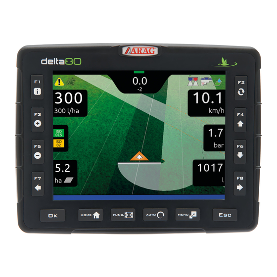
- Page 1 DELTA 80 COMPUTER WITH INTEGRATED GPS NAVIGATOR 4675000 Software rel. 2.7X INSTALLATION, USE AND MAINTENANCE *When matched to a remote control unit of the SELETRON IBX100 SERIES.
- Page 2 This manual is an integral part of the equipment to which it refers and must accompany the equipment in case of sale or change of ownership. Keep it for any future reference; ARAG reserves the right to modify product specifications and instructions at any moment and without notice.
-
Page 3: Table Of Contents
CONTENTS Risks and protections before assembly .........5 10.1.6 Valves ................. 36 MAIN VALVE Intended use ................5 • Type (REMINDER) ............36 Precautions ................5 • Automatic closing of sections valves (REMINDER) ..36 Package content ...............5 • Automatic closing of main valve ........36 •... - Page 4 CONTENTS 14 "Home" Menu ................84 10.2 IMPLEMENT GEOMETRY (MACHINE WITH TOWED/3-POINT HITCH IMPLEMENT) ..52 14.1 Continue last job ............85 10.2.1 Geometry settings (TOWED IMPLEMENT) ......52 14.2 Save job ..............86 10.2.2 Geometry settings (3-POINT HITCH IMPLEMENT) .... 53 14.3 New job ..............87 10.3 GPS RECEIVER SETTINGS .........54 14.4...
-
Page 5: Risks And Protections Before Assembly
Delta 80 features a satellite navigator that – through the external GPS receiver – can be used for agricultural applications and navigation. Delta 80 is not designed for use on public roads and should only be used on farmland. -
Page 6: Position On Farming Machine
INSTALLATION POSITION ON FARMING MACHINE CONTINUES > > >... -
Page 7: System Recommended Composition
INSTALLATION > > > 5.1 System recommended composition CONTINUES > > >... - Page 8 INSTALLATION > > > 5.1 System recommended composition...
-
Page 9: Monitor And Control Unit Positioning
Monitor and control unit positioning • The Delta 80 computer must be placed in the control cabin of the farming machine. Observe the following precautions: - Do NOT install the monitor in areas where it would be subjected to excessive vibrations or shocks, to prevent any damage or accidental use of the control keys;... - Page 10 INSTALLATION > > > 5.2 Monitor and control unit positioning ITEM CONNECTION POINTS Control unit (G + P) + Sensors Control unit (water valves) Hydraulic unit Seletron - Line 2 Seletron - Line 1 Monitor + power supply + IBX100 ECU Hydraulic (hydraulic controls) Hydraulic unit IBX100 ECU Sprayer...
-
Page 11: Bracket Fixing
WARNING: Delta 80 computer must only be fastened through the supplied bracket, using suitable screws. NO OTHER TYPE OF FASTENING IS ALLOWED. ARAG is not liable for damages to the equipment, persons or animals caused by failure to observe the above instructions. Control unit (ECU) fixing Respect the mounting direction of the control units, as specified in Fig. -
Page 12: Wiring Connections
• Use of unsuitable cables not provided by ARAG automatically voids the warranty. • ARAG is not liable for damages to the equipment, persons or animals caused by failure to observe the above instructions. General precautions for a correct harness position •... -
Page 13: Securing The Seletron Cables
Never use an extension for any other components unless you have so agreed with the ARAG Assistance Center. Choose and install the cables so that they retain some freedom of movement at boom joints. - Page 14 INSTALLATION If space is limited and you need to bend a cable, be sure not to bend it too tight or it may get damaged. MIN. RADIUS 12 cm Fig. 16 Position the cable so that branches are equally spaced from Seletron connectors Fig.
-
Page 15: Hydraulic Valve Connection
SELETRON (BODY, HARNESSES, ETC.) COME INTO CONTACT WITH MOVING PARTS AT ANY TIME WHEN THE SYSTEM IS IN USE (INSTALLATION, COMMISSIONING, USE AND SHUTDOWN OF THE FARMING MACHINE). ARAG will not be held responsible for any damage to the system, people, animals or objects caused by failure to follow the guidelines outlined above. -
Page 16: Sensor Connection
• level sensor • filling flowmeter; • RPM sensor. All ARAG sensors use the same type of connector. Connect the sensor connector to the relevant harness; make sure it is correctly fitted and push it until locking it. Fig. 22 Fig. -
Page 17: Modem
To remove the SIM card, press and immediately release the card into the slot and slide it out. Fig. 25 6.10 Pendrive The pen drive may be used to exchange data with the Delta 80 computer. Before using it make sure the pendrive is not protected. All pendrives with up to 8 GB memory are compatible. -
Page 18: Setup
Fig. 27 Fig. 28 Hold the button at the back of the monitor down for 3 seconds: after a few seconds, Delta 80 will display the page shown in Fig. 27. The software version is shown immediately afterwards (Fig. 28). -
Page 19: Switching Off
Fig. 33 Fig. 34 During switching off, Delta 80 automatically saves the current job: Do NOT press any other key and do NOT disconnect the power supply until Delta 80 turns off. WARNING: ALWAYS use the special key to switch off the device; otherwise ALL data concerning the spraying and the setup will... -
Page 20: Use Of Keys For Setup
SETUP Use of keys for setup SELECTION AND ACCESS TO MENU ITEMS 1A Press in succession to move across the menu items (UP / DOWN). The selected item is highlighted with a gray bar (A). 1B Press in succession to move across the available options (LEFT / RIGHT). -
Page 21: Menu Structure
SETUP MENU STRUCTURE Upon first switching on, run the device basic settings (chap. 9). Afterwards, it will be possible to select the preset settings by pressing chap. 14 "Home" Menu chap. 9 chap. 10 Basic settings Advanced setup Create / Load settings User usrxx ("... -
Page 22: Machine With Towed/ 3-Point Hitch Implement
SETUP "BASIC SETTINGS" BASIC SETTINGS FIRST SWITCH-ON - SETUP If you have a setup file (Backup), duly stored in a pendrive, press (A in Fig. 38) and follow the procedure described under par. 14.4.2. (B): SAVE USER AND MACHINE CONFIGURATION (STEPS 1 AND 2); IN ANY OTHER CASE, PRESS START GUIDED SETUP PROCEDURE BY MEANS OF (STEP 3). - Page 23 Self-propelled - Select (Fig. 48) and press Start basic settings procedure (Fig. 49) - Delta 80 guides you through the setup procedure: follow all suggested steps and select required options. : next step : previous step. - When message Press Ok to confirm selected settings is displayed, setup is completed.
-
Page 24: Guidance Settings
"BASIC SETTINGS" > > > 4A GUIDED SETUP PROCEDURE FOR SELF-PROPELLED MACHINES Start guidance settings procedure (Fig. 52) - Delta 80 guides you through the setup procedure: follow all suggested steps and select required options. : next step : previous step. - Page 25 Implement - Select (Fig. 54) and press Implement > Start (Fig. 55) - Delta 80 guides you through the setup procedure: follow all suggested steps and select required options. : next step : previous step. - When message Press Ok to confirm selected settings is displayed, setup is completed.
- Page 26 (Fig. 58) and press . Proceed to guided setup. Tractor > Start (Fig. 59) - Delta 80 guides you through the setup procedure: follow all suggested steps and select required options. : next step : previous step. Press Ok to confirm selected settings - When message is displayed, setup is completed.
-
Page 27: Advanced Setup
ADVANCED SETUP ADVANCED SETUP ACTIVE SETTINGS Before proceeding with advanced setup, select type of system configuration: all advanced setup changes will be applied to ACTIVE SETTINGS ( self-propelled with towed/3-point hitch machine implement SETUPS MANAGEMENT 1 Press in the "Home" screen (Fig. 61). Now it is possible to create a new setup (2A), or select an existing one (2B): in all cases the setup will be enabled and the name will be displayed in the "Home"... - Page 28 ADVANCED SETUP LOADING A SETUP Instead of saving, you can activate a previously saved setup. Load > Configuration Select in Fig. 69) and press From the example of Fig. 70 select type of setup to load and press Follow all suggested steps and select required options. : next step : previous step.
- Page 29 1 In the "Home" screen (Fig. 72) press to enter the menu (Fig. 73 / Fig. 74). 2 Proceed with Delta 80 advanced setup: select the required menu item (using 3 Use Fig. 72 to go to selected item setup.
-
Page 30: Implement Advanced Settings
ADVANCED SETUP "IMPLEMENT" 10.1 IMPLEMENT ADVANCED SETTINGS 10.1.1 Spray spots configurations Allows setting 20 different configurations (i.e., 20 nozzle combinations), which can be selected before starting each job. Each configuration indicates which type of nozzle is installed on the boom's spraying points. Spraying point Nozzle A Nozzle A... -
Page 31: Boom Settings
ADVANCED SETUP "IMPLEMENT" 10.1.2 Boom settings The operator may choose the way in which the boom is subdivided into different sections: this is done in order to act on the corresponding switch when closing sections manually. With automatic management, instead, the computer acts on each single Seletron separately. Spray spots spacing Boom... -
Page 32: Activation Status Of The Sections
ADVANCED SETUP "IMPLEMENT" • Section 1 ÷ 13 - Indicate the number of spraying points (nozzle holders) installed on each boom section. - Repeat the setup for each section (Fig. 79). Fig. 85 SECTIONS MANAGEMENT • Activation status of the sections It allows to enable/disable specific boom sections. -
Page 33: Flowmeter
ADVANCED SETUP "IMPLEMENT" 10.1.3 Flowmeter Enter the values for the flowmeter installed on the system. The table below indicates the values that are automatically set when selecting the flowmeter code. Other If the installed flowmeter is not displayed, select and enter the relevant values. ORION FLOWMETERS WOLF FLOWMETERS Constant Minimum... -
Page 34: Filling Flowmeter
ADVANCED SETUP "IMPLEMENT" 10.1.4 Filling flowmeter This menu is only visible when the filling flowmeter is selected as tank level source (basic settings, chap. 9). The filling flowmeter allows displaying the tank filling data in real time. Enter the values for the filling flowmeter installed on the system: the table below indicates the values that are automatically set when selecting the flowmeter code. -
Page 35: Pressure Sensor
- Enter the values for the pressure sensor installed on the system. The table below indicates the values that are automatically set selecting the sensor code. Other If the installed sensor is not displayed, select and enter the relevant values. ARAG PRESSURE SENSOR Maximum pressure Type ARAG 466113.200 20.0 ARAG 466113.500... -
Page 36: Valves
ADVANCED SETUP "IMPLEMENT" 10.1.6 Valves Set the type of valve installed on the system and the relevant values. Main valve > Type Automatic closing of sections valves The items appear as a REMINDER: they are enabled during guided setup (chap. 9). Therefore, they cannot be modified from this screen. -
Page 37: Type (Reminder)
ADVANCED SETUP "IMPLEMENT" > > > 10.1.6 Valves SECTION VALVES • Type (REMINDER) 2 ways On a Seletron system, section valves are of the type (without calibrated backflows) and are automatically set. Fig. 102 • Shut-off time Indicate the time between the moment when the command is sent to the Seletron valves and the actual moment in which product output stops. -
Page 38: Nozzles Data
For the procedure to be followed when an alarm occurs, please refer to par. 17.1 Error messages. Pressure limits for the nozzle in use allow Delta 80 to select the suitable nozzle during spraying, therefore they must be set correctly. Fig. 109 Fig. -
Page 39: Wheel Sensor
10.1.8 Wheel sensor Information concerning speed is usually received by the GPS, which is connected directly to Delta 80. If there is no GPS signal this menu allows to use the wheel sensor as a source of speed data instead of the GPS, and therefore to calculate the data on the basis of the pulses received by the speed sensor installed on the wheel. -
Page 40: Tank
ADVANCED SETUP "IMPLEMENT" 10.1.10 Tank Tank level source: Tank level source: Manual / Filling flowmeter Level sensor Allows setting the tank values. The settings will change according to the selected tank level source (basic settings, chap. 9). Fig. 116 Fig. 117 TANK LEVEL SOURCE: MANUAL / FILLING FLOWMETER •... -
Page 41: Reserve Level
ADVANCED SETUP "IMPLEMENT" TANK LEVEL SOURCE: LEVEL SENSOR • Reserve level Indicate range value. The tank alarm is triggered when, during spraying, the tank level falls below the set value. For the procedure to be followed when an alarm occurs, please refer to par. 17.1 Error messages. Fig. -
Page 42: Alarms
This alarm can be enabled ONLY if the system features both flowmeter and pressure sensor. • Nozzle wear limit percentage Set the acceptable threshold: Delta 80 compares the effective rate read by the flowmeter and the one calculated by the pressure sensor. -
Page 43: Minimum Flowrate Alarm
ADVANCED SETUP "IMPLEMENT" > > > 10.1.11 Alarms FLOWMETER ALARMS • Minimum flowrate alarm • Maximum flowrate alarm Allows to enable/disable minimum and maximum flowrate alarms for the flowmeter. - Select the item you wish to set up. - Enable/disable the alarm ( Alarm enabled / Alarm disabled). -
Page 44: Working Parameters
Limit enabled Limite disattivato • Minimum spraying speed Set the minimum spraying speed: Delta 80 closes the main valve when the tractor speed is lower than the set value. Fig. 129 Fig. 130 • Regulation pressure limit... -
Page 45: Sections Overlapping Limit
• Sections overlapping limit Set the acceptable threshold for overlapping of already-sprayed areas. When this value is exceeded, Delta 80 restores the correct spraying: depending on the section management mode enabled (par. 13.7 Boom section management), Delta 80 will prompt the operator to close the relevant valves or proceed to the automatic closing of the spraying points. -
Page 46: Spray Closing Delay
ADVANCED SETUP "IMPLEMENT" > > > 10.1.12 Working parameters • Spray closing delay Indicate the distance corresponding to the delayed closing of sections during spraying, to ensure correct spraying range. NOTE: Negative values indicate that sections are closed in advance with respect to the calculated point. Closing delay: 0.3 m Fig. -
Page 47: Reference Lines Distance Offset
ADVANCED SETUP "IMPLEMENT" • Reference lines distance offset This value allows changing the distance between the reference tracks. +0.5 m +0.5 m When the value is positive, the distance between the reference tracks (black lines) decreases. The spray lateral sides overlap. Fig. - Page 48 ADVANCED SETUP "IMPLEMENT" 10.1.13 Trail control • Status To configure the items on this menu, you must enable the trail control Trail control enabled / Trail control disabled). Enter the values for the trail control installed on the system. • Minimum activation speed •...
-
Page 49: Device Calibration
• Tank level zero value In the cases below it is necessary to perform the level sensor zero adjustment. 1 Delta 80 displays the presence of fluid inside the tank, even when it is empty; 2 A tank profile has been loaded (par. 10.1.10). -
Page 50: Tank Profile Calibration
ADVANCED SETUP "IMPLEMENT" • Tank profile calibration The calibration of the tank profile is ONLY possible if a flowmeter is installed on the system (par. 10.1.3). Before starting the procedure carry out the following operations: 1 Make sure the main switch is in position OFF (Fig. 157). 2 Fill the tank with clean water WITHOUT ADDING CHEMICAL SUBSTANCES. -
Page 51: Pressure Sensor Zero Value
ADVANCED SETUP "IMPLEMENT" • Pressure sensor zero value To access this menu, the pressure sensor must be enabled ( , par. 10.1.5) In case a pressure value other than zero is displayed despite the absence of pressure inside the circuit, it is necessary to perform zero calibration of the sensor. -
Page 52: Geometry Settings (Towed Implement)
ADVANCED SETUP "TOWED IMPLEMENT GEOMETRY" 10.2 IMPLEMENT GEOMETRY (MACHINE WITH TOWED/3-POINT HITCH IMPLEMENT) The display layout of this menu depends on the selected basic settings (chap. 9). FOR GEOMETRY OF SELF-PROPELLED MACHINES REFER TO PAR. 10.5.2 AND 10.5.3. 10.2.1 Geometry settings (TOWED IMPLEMENT) Settings displayed next will depend on set type of system (chap. -
Page 53: Geometry Settings (3-Point Hitch Implement)
ADVANCED SETUP "3-POINT HITCH IMPLEMENT GEOMETRY" 10.2.2 Geometry settings (3-POINT HITCH IMPLEMENT) Settings displayed next will depend on set type of system (chap. 9). Enter farming machine measures (Fig. 174). - Press the arrow keys (UP, DOWN) to move across value descriptions: the image of the selected value will appear on the display. -
Page 54: Gps Receiver Settings
10.3.3 Tilt compensation Fig. 181 Fig. 182 Allows to enable/disable the tilt compensation function of the vehicle (with antenna only. See ARAG catalog). Tilt compensation enabled / Tilt compensation disabled). Delta 80 can set off any measurement errors due to ground inclination. -
Page 55: Correction Type
Omnistar correction signal is available worldwide for a fee and allows to obtain high working accuracy. ® WARNING! The differential correction service subscription is not managed by ARAG, but directly by Omnistar ® For more information on the subscription, visit Omnistar 's website. - Page 56 ADVANCED SETUP "AUTONOMOUS GUIDANCE" 10.4 Autonomous guidance The display layout of this menu depends on the selected basic settings (chap. 10.4.1 Response rate 10.4.2 Reverse response rate 10.4.3 Swath acquisition response rate Scroll Scroll Enter Delete Data Confirm access Exit the function or selected selected (LEFT /...
- Page 57 ADVANCED SETUP "AUTONOMOUS GUIDANCE" 10.4.4 Motor aggressiveness 10.4.5 Heading aggressivenes 10.4.6 Cross track error 10.4.7 Guidance configuration Scroll Scroll Enter Delete Data Confirm access Exit the function or selected selected (LEFT / (UP / increase / or data change data change Par.
-
Page 58: Tractor Advanced Settings
TRACTOR ADVANCED SETTINGS 10.5.1 Camera Delta 80 can connect to up to 2 cameras in order to monitor the working areas that the operator is unable to see (e.g., when driving in reverse). From the menu it is possible to enable/disable each single camera individually or both cameras: No camera connected 1 camera connected to input no.1... -
Page 59: Geometry Settings (Self-Propelled With Front Boom)
ADVANCED SETUP "TRACTOR" 10.5.3 Geometry settings (SELF-PROPELLED WITH FRONT BOOM) Settings displayed next will depend on set type of system (chap. 9). Enter farming machine measures (Fig. 193). - Press the arrow keys (UP, DOWN) to move across value descriptions: the image of the selected value will appear on the display. -
Page 60: Geometry Settings (Tractor With Towed/3-Point Hitch Implement)
ADVANCED SETUP "TRACTOR" 10.5.4 Geometry settings (TRACTOR WITH TOWED/3-POINT HITCH IMPLEMENT) Settings displayed next will depend on set type of system (chap. 9). Enter farming machine measures (Fig. 199). - Press the arrow keys (UP, DOWN) to move across value descriptions: the image of the selected value will appear on the display. -
Page 61: User
ADVANCED SETUP "USER" 10.6 USER Alarm Delta 80 features an menu (Fig. 206, accessible from the "Home" menu by pressing ). This page displays all active notifications for the operator. These notifications are rated by importance as Critical alarms Low priority alarms... -
Page 62: Steering Warning
ADVANCED SETUP "USER" 10.6.4 Steering warning It allows to enable/disable the acoustic signal when the operator must steer in order to align the machine Steering with the following track, avoiding unsprayed or overlapping areas between the two sprays ( radius set in par. -
Page 63: Guidance
ADVANCED SETUP "USER" GUIDANCE 10.6.8 Offset tolerance 120 cm 90 cm 60 cm 30 cm Vehicle offset from reference line is represented by the LED bar on the side (guidance screen). Each LED on indicates an offset value Offset corresponding to the one set in item tolerance (for ex.: 30 cm). -
Page 64: General Options
ADVANCED SETUP "GENERAL OPTIONS" 10.7 GENERAL OPTIONS Set the device system options: Language • (par. 10.7.1). Units of measurement • (par. 10.7.2). Date and time GPS updating • (par. 7). Date and time • (par. 10.7.4). Fig. 218 10.7.1 Language Set the computer language. -
Page 65: Date And Time Gps Updating
ADVANCED SETUP "GENERAL OPTIONS" 10.7.3 Date and time GPS updating Allows to enable / disable computer automatic date and time updating. Acquisition enabled The local time, date and timezone will be constantly updated thanks to the signal picked up by the GPS receiver. -
Page 66: Device Status
The aspect of this menu depends on the selected basic settings (chap. 9), which affect which items are displayed in Fig. 223. 10.8 DEVICE STATUS Allows checking the correct operation of Delta 80: the description of the selected item will appear on the display. Displayed items are READ-ONLY. DEVICE TOTALIZERS Allows user to view total spraying data, concerning sprayed area and work time Fig. -
Page 67: External Signals
EXTERNAL SIGNALS Delta 80 detects frequency and current output by each sensor on the system. Fig. 225 Delta 80 displays the status of the external main control which starts the spraying. Fig. 226 Delta 80 detects the driving direction. Fig. 227 POWER DATA Delta 80 checks the status of the power supply. -
Page 68: Seletron Connection
LOCATED IN THE CABIN (DOORS OPEN, ETC.). • Access the menu Settings > Device status > Status of the Seletron system on Delta 80 (par. 10.8). • Make sure that ALL SELETRON DEVICES ARE DISCONNECTED: they must be shown on the display only with the symbols , as shown in Fig. - Page 69 ADVANCED SETUP "DEVICE STATUS" The products are supplied with valve installation instructions. Make sure the device is correctly fitted and push it until locking it. When the cable is inserted in the connector, the Seletron is sealed. To avoid damaging the internal components, make sure that when using or cleaning the system the connectors are not bare or inserted incorrectly.
-
Page 70: Preliminary Operations
ADVANCED SETUP "DEVICE STATUS" SELETRON REPLACEMENT 11.1 Preliminary Operations TO AVOID ACCIDENTS, EMPTY THE TANK AND MAKE SURE THAT THE ENTIRE SYSTEM IS COMPLETELY FREE FROM CHEMICALS. IMPORTANT: Set the main switch and section switch to ON. Enable all nozzles and disable all automatic functions par. - Page 71 Alternatively, if you do not have a torque wrench, tighten the Seletron devices by hand and make sure there are no leaks. ARAG IS NOT LIABLE FOR ANY DAMAGE OR MALFUNCTION CAUSED BY THE USE OF TOOLS DIFFERENT FROM THE ONES INDICATED ABOVE.
-
Page 72: Use
12.1 Controls on computer Legend: 1 Control and display mode keys 2 Function keys. Function keys are contextual: the function of each depends on what appears on the display, therefore the use of these keys will be illustrated during the description of the corresponding procedures. -
Page 73: Operating Switches For Control Unit Valves
12.2 Operating switches for control unit valves Increase Decrease Main control ON Main control OFF Open section Closed section of output of output • Switches for sequential control Section operating switches Increase Decrease Main control ON Main control OFF of output of output Open section Closed section... -
Page 74: Buffer Zone" Function Enabled
12.2.1 "Buffer Zone" function enabled Some spraying jobs provide for zones called "Buffer zone", where spraying must be reduced or shut off. Further to the nozzles usually used, it is necessary to install special nozzles (e.g.: ASJ AOC), able to reduce the spray or drift, as terminal nozzles on boom. -
Page 75: Guidance Screen
12.4 Guidance screen USING THE KEYS Displays job information / alarms (par. 15.1) Display zoom adjustment: ) zoom in ) zoom out Select job data Select job data displayed on the displayed on the LEFT side RIGHT side Go to “Home” View automatic Aborts a function menu... -
Page 76: Spraying A Field
If there is at least one map (on the internal memory), you can select a prescription map for the spraying. According to the position detected by the GPS receiver, Delta 80 will use the appropriate spray rate for the area that is being sprayed (par. - Page 77 (Fig. 254). Fig. 254 Fig. 253 At the beginning of a new job Delta 80 gives driving directions in the "Straight parallel" mode. Guidance mode (par. 16.2). To change guidance mode see function > > > 12.5 Spraying a field...
-
Page 78: Automatic Functions
"AUTOMATIC FUNCTIONS" - STRUCTURE AUTOMATIC FUNCTIONS New job Resume job To access automatic functions, start a job ( Continue last job , chap. 14 "Home" Menu); Auto in the guidance screen press . When the list is active (Fig. 255), pressing the key at the side will enable the relevant function. -
Page 79: Output Adjustment
• In the job start screen select the desired prescription map. • Proceed with the job. According to the position detected by the GPS receiver, Delta 80 will use the appropriate spray rate for the area that is being sprayed (Fig. 257). -
Page 80: How The Automatic Nozzle Selection Works (Seletron System)
This operation field can be restrictive for the features of both crop to be treated and machine. Operation field of possible combinations of ISO11002 and ISO110025 nozzles When automatic nozzle selection is enabled, Delta 80 (using Seletron devices) will enable the nozzle, or combination of nozzles, according to the set spray rate and driving speed. -
Page 81: F4 Automatic Nozzle Selection On/Off
"AUTOMATIC FUNCTIONS" - MANUAL / AUTOMATIC NOZZLE SELECTION 13.5 Automatic nozzle selection ON/OFF Enables / disables automatic nozzle selection on all spraying points (DEFAULT: ON). Auto 1 In the guidance screen, press 2 Press (Fig. 262) to enable or disable automatic selection. NOZZLE A Automatic selection Automatic selection... -
Page 82: Boom Section Management
As the machine advances, the signal is triggered for each valve. When overlapping returns within the set limit, Delta 80 warns to OPEN the relevant spraying points (Fig. 265). Open the valves through the relevant switches: Delta 80 will confirm opening on display. As the machine advances, the signal is triggered for each valve. -
Page 83: F6 Automatic Section Management On/Off
"AUTOMATIC FUNCTIONS" - F6 AUTOMATIC SECTION MANAGEMENT ON/OFF 13.8 Automatic section management ON/OFF Enables / disables automatic boom section management (DEFAULT: ON). Auto 1 In the guidance screen, press 2 Press (Fig. 268) to enable or disable automatic management. Automatic section Automatic section management management... -
Page 84: 14 "Home" Menu
"HOME" MENU - STRUCTURE "HOME" MENU Fig. 269 Home To enter the menu press the key: once inside the menu, pressing each key will enable the corresponding function. The table below sums up all menu items and corresponding keys: Par. Par. -
Page 85: F1 Continue Last Job
"HOME" MENU - F1 CONTINUE LAST JOB 14.1 Continues last job. Continue last job 1 Press to continue the last job, from the point where it has been interrupted. Spraying settings 2 Check the in Fig. 271; modify them if necessary. 3 Select and press to switch to guidance mode. -
Page 86: F2 Save Job
"HOME" MENU - F2 SAVE JOB 14.2 Save current job Save job Fig. 273 Fig. 274 1 Press to save current job: the name edit screen is displayed (Fig. 274). Type the name. 2A Press in succession to select the character you wish to type (UP / DOWN) 2B Press in succession to select the character you wish to type (RIGHT / LEFT). -
Page 87: F3 New Job
Start a new spraying New job 1 Press to start a new spraying. If the current job has not been saved yet, Delta 80 will prompt the user to save it (Fig. 276). Press to continue without saving (2A) or to interrupt the procedure and save (2B). -
Page 88: F4 Memories Management
Memories management Allows to upload, save and/or delete the data memorized on Delta 80 or on an external memory (Pendrive); said data concern jobs carried out, maps or machine configurations. All operations are described in detail in the following paragraphs. -
Page 89: Backup
"HOME" MENU - F4 MEMORIES MANAGEMENT 14.4.2 Backup It manages exchange of system settings between Delta 80 and an external memory (Pendrive). Memories management Press to enter • Create backup file on USB1 Allows to save a (backup) copy of system settings to USB pendrive. -
Page 90: Internal Memory Deletions
"HOME" MENU - F4 MEMORIES MANAGEMENT 14.4.3 Internal memory deletions Allows to delete data from Delta 80 internal memory. THE CURRENTLY USED FILES MUST NOT BE DELETED. Implements Tractors, Users, The following paragraphs will use as an example: the same procedure will be valid for all other cases ( etc.). -
Page 91: Remote Devices Upgrade
"HOME" MENU - F4 MEMORIES MANAGEMENT 14.4.5 Remote devices upgrade • Upgrade files Allows to upgrade the software of the devices connected to Delta 80: ECU IBX100 (remote control unit), switch panel, etc. Before starting the procedure copy the upgrade files onto the pendrive. - Page 92 2 Scroll the list: select the desired file from the list (Fig. 297) and press Available upgrades: IBX100 Aragnet Sprayer • (for ECU with water controls) IBX100 Hydraulic Arag • (for ECU with hydraulic controls) Fig. 297 SWITCHBOX •...
-
Page 93: Upgrade Monitor Firmware
Fig. 301 - Select the upgrade file and drop it onto the pendrive explorer window. WARNING: save file in the main directory of the USB pendrive or Delta 80 will not be able to read it. Fig. 302 - Insert the pendrive in its slot on Delta 80. -
Page 94: F5 Resume Job
2 Select the job among those in the list (Fig. 306) and press to confirm the selection. 2a When an "old" job is resumed, Delta 80 provides guidance information by restoring the conditions which were active at the time of saving. Loading options If the screen is enabled (see par. -
Page 95: F6 Info / Alarms
"HOME" MENU - F6 INFO / ALARMS 14.6 Displays job information / alarms. Info / Alarms Info / Alarms 1 Press to view the menu (Fig. 311). This screen gives an overview of the active notifications for the operator, rated Critical alarms by importance as priority alarms... -
Page 96: Job Menu
"JOB MENU" - STRUCTURE JOB MENU New job Resume job Continue last job To access job menu start a job ( , chap. 14 Menu "Home" Menu); in the guidance screen press In the job menu (Fig. 312), pressing any key at the side will enable the relevant function. -
Page 97: F1 Info / Alarms
"JOB MENU" - F1 INFO / ALARMS 15.1 Displays job information / alarms Info / Alarms 1 In the guidance screen, press Menu Info / Alarms 2 Press to view the menu (Fig. 314). Critical alarms Low priority This screen gives an overview of the active notifications for the operator, rated by importance as alarms Info Fig. -
Page 98: F2 Job Data
"JOB MENU" - F2 JOB DATA 15.2 Displays job data Job data Menu 1 In the guidance screen, press 2 Press to view job data (Fig. 316 and Fig. 317). 3 Press to scroll data. Fig. 315 Fig. 316 Data and units of measurement shown are listed in par. -
Page 99: F3 Tank
"JOB MENU" - F3 TANK Manages tank filling. 15.3 The management mode will change according to the device set for the tank level reading Tank (basic settings, chap. 9). Menu 1 In the guidance screen, press Tank 2 Press to view the menu (Fig. -
Page 100: F4 Gps Data
This screen shows the data sent to the GPS receiver. Enabled for GPS receiver Smart-Ag Tilt and Smart 6T models only. (see General ARAG Cat.) A description of the selected data is shown at the bottom of the display. Fig. 323 Fig. -
Page 101: F5 Camera
"JOB MENU" - F5 CAMERA 15.5 Displays images from connected cameras Camera 1 In the guidance screen, press Menu Camera 2 Press to view the menu (Fig. 326). By connecting one or more cameras, it is possible to monitor working areas and at the same time view spraying data. Enable camera view during advanced setup (par. -
Page 102: F6 Prescription Map
"JOB MENU" - F6 PRESCRIPTION MAP 15.6 Overview of the prescription map in use Prescription map 1 In the guidance screen, press Menu Prescription map 2 Press to view the menu (Fig. 328). From this screen it is possible to view data of the prescription map during spraying and to check the position of the machine on the map. -
Page 103: F7 Zoom All
"JOB MENU" - F7 ZOOM ALL 15.7 Overview of the field during spraying Zoom all 1 In the guidance screen, press Menu Zoom all 2 Press to view the menu (Fig. 330). Fig. 329 INDICATORS AND POINTS OF INTEREST ON THE FIELD Job interruption point, enabled with the "PAUSE"... - Page 104 "JOB MENU" - F7 ZOOM ALL MARKING POINTS OF INTEREST The general points of interest can be memorized with this procedure or with the specific function (par. 16.3.2). It is possible to mark more points. In this screen it is possible to memorize one point of the field even if the tractor is in another position: 1 In field overview screen (Fig.
-
Page 105: F8 Menu
Allows to select the source for speed calculation. Available options: • GPS Information concerning speed is received by the GPS, which is connected directly to Delta 80. • Wheel sensor When this option is enabled, the speed is calculated on the basis of the pulses received by the speed sensor installed on the wheel. -
Page 106: Job Functions
"JOB FUNCTIONS" - STRUCTURE JOB FUNCTIONS New job Resume job To access job functions start a job ( Continue last job , chap. 14 "Home" Menu); Func in the guidance screen press When the list is active (Fig. 340), pressing the key at the side will enable the relevant function. -
Page 107: F1 Spray Rate
"JOB FUNCTIONS" - F1 SPRAY RATE 16.1 Spray rate Change spray rate 1 In the guidance screen, press Func 2 Press to enable the function. 3 Change the spray rate value for the job (Fig. 342). 4 Confirm the data. Fig. -
Page 108: F2 Guidance Mode
The trajectory between will be saved and Delta 80 will create evenly distributed tracks. Upon creation of the reference track, any bends in the trajectory between will be ignored. - PIVOT MODE - FREE GUIDANCE MODE Fig. -
Page 109: F3 Point Marking
Fig. 351): the symbol will be placed exactly on that point. Delta 80 can save ONLY ONE BREAKING POINT: every time you save a point, the previous one will be deleted. Fig. 351 Saving of general points of interest 16.3.2... -
Page 110: F4 Surface
"JOB FUNCTIONS" - F4 SURFACE 16.4 Surface Enables the procedure to calculate field surface by driving along its perimeter. 1 In the guidance screen, press Func 2 Press to start the surface calculation procedure (function list disappears). Field edge side selection The following message will appear: prompting the operator to select which side of the machine to use as a reference to define the field perimeter. -
Page 111: F5 Resume From Pause
When you are close to it, you can see it on the display. 4 Once you have reached the position, the value of the distance reaches "zero" (Fig. 360): press to exit the procedure. Delta 80 goes back to displaying guidance information for the job and the symbol is erased. -
Page 112: Align
"JOB FUNCTIONS" - F6 ALIGN Moves the closest reference track, re-aligning it to the position of the machine. 16.6 Align This function is useful when you need to re-align the machine, whilst continuing to drive in the same direction (for example, for corn, sugar cane). 1 In the guidance screen, press Func 2 Press... -
Page 113: F7 New Ab
"JOB FUNCTIONS" - F7 NEW AB Saves two points A and B on the field, which Delta 80 uses to draw a line that will act as a reference 16.7 New AB track ( , Fig. 365) for the current job. -
Page 114: F8 Display
"JOB FUNCTIONS" - F8 DISPLAY Allows to select different display modes. Includes several functions: 16.8 Display 1 In the guidance screen, press Func 2 Press . A list of options concerning display modes will appear (Fig. 366). Pressing each key will enable the corresponding function: changes tractor themes (par. -
Page 115: F4 Spraying Themes
"JOB FUNCTIONS" - F8 DISPLAY 16.8.2 Spraying themes 1 In the guidance screen, press Func 2 Press to view the available options. 3 Press in succession to scroll spraying color combinations. SPRAYING THEME 1 (DEFAULT) THEME 2 THEME 3 THEME 4 THEME 5 Fig. -
Page 116: Maintenance / Diagnostics / Repairs
(par. 5.2) The cables are damaged • Replace the cable • Check connection to receiver (par. 5.2) Wrong connection of receiver cable to Delta 80 GPS receiver not connected! The receiver connection cable is damaged • Replace the cable The receiver is damaged •... - Page 117 MAINTENANCE / DIAGNOSTICS / REPAIRS MESSAGE ON DISPLAY CAUSE REMEDY JOB MODE Signal from pressure sensor is out of allowed • Check the sensor and connection cable (and Invalid signal of the pressure sensor! connector) status (par. 6.6) range Master ON •...
- Page 118 MAINTENANCE / DIAGNOSTICS / REPAIRS MESSAGE ON DISPLAY CAUSE REMEDY JOB MODE Communication problems between monitor and • Check condition of connection cables switches (and connectors) between monitor and switch box Switch box connection not detected! The cables are damaged •...
-
Page 119: Troubleshooting
MAINTENANCE / DIAGNOSTICS / REPAIRS 17.2 Troubleshooting FAULT CAUSE REMEDY No power supply • Check power supply connection The display does not switch on Computer is OFF • Press the ON key Valve controls take no effect Valves not connected •... -
Page 120: Technical Data
TECHNICAL DATA TECHNICAL DATA DESCRIPTION Delta 80 Display LCD 8.4", 65000 colors, 500 cd/m Rated supply voltage 12 Vdc (9 ÷ 16 Vdc) Consumption (valves excluded) monitor: 1.5 A 0 °C ÷ 45 °C Operating temperature +32 °F ÷ +113 °F -20 °C ÷... - Page 121 TECHNICAL DATA > > > 18.1 Data and units of measurement shown Implement Menu Data Min. Max. DEFAULT Other values that can be set / Notes l/min 0.40 l/min Flowrate 0.10 GPM l/min 0.60 l/min Flowrate 0.15 GPM l/min 0.80 l/min Flowrate 0.20 GPM l/min...
- Page 122 TECHNICAL DATA > > > 18.1 Data and units of measurement shown Implement Menu Data Min. Max. DEFAULT Other values that can be set / Notes Spraying speed limit Disabled Enabled 99.9 km/h 1.0 km/h Minimum spraying speed 99.9 0.6 mph Regulation pressure limit Disabled Enabled...
- Page 123 TECHNICAL DATA > > > 18.1 Data and units of measurement shown Tractor Menu Data Min. Max. DEFAULT Other values that can be set / Notes 0.50 20.00 2.80 m Wheelbase 0.50 64.00 9.19 ft 0.00 20.00 1.50 m Rear axle / Application point 0.00 64.00 4.92 ft...
-
Page 124: End-Of-Life Disposal
GUARANTEE TERMS 1. ARAG s.r.l. guarantees this apparatus for a period of 360 days (1 year) from the date of sale to the client user (date of the goods delivery note). The components of the apparatus, that in the unappealable opinion of ARAG are faulty due to an original defect in the material or production process, will be repaired or replaced free of charge at the nearest Assistance Center operating at the moment the request for intervention is made. - Page 125 Via Palladio, 5/A 42048 Rubiera (RE) - Italy P.IVA 01801480359 Dichiara che il prodotto descrizione: Computer modello: Delta 80 serie: 4675000 risponde ai requisiti di conformità contemplati nelle seguenti Direttive Europee: 2004/108/CE (Compatibilità Elettromagnetica) Riferimenti alle Norme Applicate: UNI EN ISO 14982 (Macchine agricole e forestali - Compatibilità...
- Page 126 Only use genuine ARAG accessories or spare parts to make sure manufacturer guaranteed safety conditions are maintained in time. Always refer to ARAG spare parts catalog. 42048 RUBIERA (Reggio Emilia) - ITALY Via Palladio, 5/A Tel. +39 0522 622011 Fax +39 0522 628944 http://www.aragnet.com...
Need help?
Do you have a question about the DELTA 80 and is the answer not in the manual?
Questions and answers