Table of Contents
Advertisement
Quick Links
For questions or help with this product contact Tech Support at (570) 546-9663 or techsupport@grizzly.com
The following change was recently made to these machines since the owner's manual was printed:
•
G0768 wiring diagram has been updated (replaces Page 90).
G0769 wiring diagram has been updated (replaces Page 93).
•
Aside from this information, all other content in the owner's manual applies and MUST be read and under-
stood for your own safety. IMPORTANT: Keep this update with the owner's manual for future reference.
For questions or help, contact our Tech Support at (570) 546-9663 or techsupport@grizzly.com.
WARNING: NO PORTION OF THIS MANUAL MAY BE REPRODUCED IN ANY SHAPE
OR FORM WITHOUT THE WRITTEN APPROVAL OF GRIZZLY INDUSTRIAL, INC.
READ THIS FIRST
COPYRIGHT © JULY, 2017 BY GRIZZLY INDUSTRIAL, INC.
#JH19074 PRINTED IN CHINA
Model G0768 & G0769
***IMPORTANT UPDATE***
For Machines Mfd. Since 6/17
and Owner's Manual Printed 6/17
Advertisement
Table of Contents

Related Manuals for Grizzly G0768


Summary of Contents for Grizzly G0768
- Page 1 For Machines Mfd. Since 6/17 and Owner's Manual Printed 6/17 For questions or help with this product contact Tech Support at (570) 546-9663 or techsupport@grizzly.com The following change was recently made to these machines since the owner's manual was printed: •...
- Page 2 (Replaces Page 90 in Manual) G0768 Wiring Diagram READ ELECTRICAL SAFETY G0768/G0769 Update (Mfd. Since 2/17) ON PAGE 42!
- Page 3 (Replaces Page 93 in Manual) G0769 Wiring Diagram READ ELECTRICAL SAFETY G0768/G0769 Update (Mfd. Since 2/17) ON PAGE 42!
- Page 5 (For models manufactured since 8/15) Model G0768 Model G0769 COPYRIGHT © AUGUST, 2014 BY GRIZZLY INDUSTRIAL, INC. REVISED JUNE, 2017 (HE) WARNING: NO PORTION OF THIS MANUAL MAY BE REPRODUCED IN ANY SHAPE OR FORM WITHOUT THE WRITTEN APPROVAL OF GRIZZLY INDUSTRIAL, INC.
- Page 6 This manual provides critical safety instructions on the proper setup, operation, maintenance, and service of this machine/tool. Save this document, refer to it often, and use it to instruct other operators. Failure to read, understand and follow the instructions in this manual may result in fire or serious personal injury—including amputation, electrocution, or death.
-
Page 7: Table Of Contents
Centers ............41 End Gears, Pulleys, V-Belts ........Milling Headstock (G0769 Only) ......... Dead Centers ............G0768 Data Sheet ......... 9 Mounting Dead Center in Spindle ......G0769 Data Sheet ........11 Removing Center from Spindle ......... Mounting Center in Tailstock ........ - Page 8 G0769 Mill Column ........103 Ball Oilers ..............G0769 Mill Headstock ........ 104 Leadscrew & Carriage Rack ........G0768 Labels & Cosmetics ....... 106 Bedways ..............G0769 Labels & Cosmetics ....... 107 Feed Gearbox ............G0768 Electrical Component Diagram ..108 Cross Slide &...
-
Page 9: Introduction
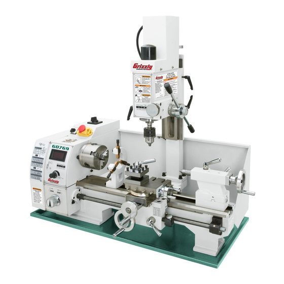
INTRODUCTION Machine Description Manual Accuracy The Model G0768 and G0769 share lathe fea- We are proud to provide a high-quality owner’s tures such as a 600 Watt ( ⁄ HP) 110V DC motor, manual with your new machine! variable-speed controls with digital RPM display, high/low spindle speed ranges, 4"... -
Page 10: Identification (G0768)
Speed Dial Feed Direction Thread Dial Dial Carriage Carriage Cross Slide Handwheel Half Nut Lock Handwheel Lever Figure 1. Model G0768 identification. To reduce your risk of serious injury, read this entire manual BEFORE using machine. Model G0768/G0769 (Mfd. Since 8/15) -
Page 11: Identification (G0769)
Downfeed Handle 4-Way Tool Post Tailstock Spindle Speed Display Spindle Speed Dial Feed Direction Dial Carriage Lock Compound Rest Cross Slide Handwheel Thread Handwheel Dial Carriage Half Nut Handwheel Lever Figure 2. Model G0769 identification. Model G0768/G0769 (Mfd. Since 8/15) -
Page 12: Controls & Components
Thread Dial: Indicates when to engage the D. Spindle Direction Switch: Selects spindle half nut during threading operations. rotation direction. M. Half Nut Lever: Engages/disengages half nut for power feeding and threading opera- tions. Model G0768/G0769 (Mfd. Since 8/15) -
Page 13: Tailstock
S. Offset Scale: Indicates relative distance of tailstock offset from spindle centerline. Tailstock Offset Screws: Adjusts tailstock offset left or right from spindle centerline (1 of Model G0768/G0769 (Mfd. Since 8/15) -
Page 14: Milling Headstock (G0769 Only)
AA. Coarse Downfeed Handles: Moves spindle down quickly when rotated and automatic spring return brings spindle back up to top when you release downward pressure on handles. Typically used for drilling holes or checking spindle positioning during setups. Model G0768/G0769 (Mfd. Since 8/15) -
Page 15: G0768 Data Sheet
MACHINE DATA SHEET Customer Service #: (570) 546-9663 · To Order Call: (800) 523-4777 · Fax #: (800) 438-5901 MODEL G0768 8" X 16" VARIABLE‐SPEED LATHE Product Dimensions: Weight................................144 lbs. Width (side-to-side) x Depth (front-to-back) x Height................36 x 16 x 14 in. - Page 16 The information contained herein is deemed accurate as of 6/28/2017 and represents our most recent product specifications. Model G0768 PAGE 2 OF 3 Due to our ongoing improvement efforts, this information may not accurately describe items previously purchased. -10- Model G0768/G0769 (Mfd. Since 8/15)
-
Page 17: G0769 Data Sheet
The information contained herein is deemed accurate as of 6/28/2017 and represents our most recent product specifications. Model G0769 PAGE 1 OF 3 Due to our ongoing improvement efforts, this information may not accurately describe items previously purchased. -11- Model G0768/G0769 (Mfd. Since 8/15) - Page 18 The information contained herein is deemed accurate as of 6/28/2017 and represents our most recent product specifications. Model G0769 PAGE 2 OF 3 Due to our ongoing improvement efforts, this information may not accurately describe items previously purchased. -12- Model G0768/G0769 (Mfd. Since 8/15)
-
Page 19: Section 1: Safety
Everyday ery. Never operate under the influence of drugs or eyeglasses are NOT approved safety glasses. alcohol, when tired, or when distracted. -13- Model G0768/G0769 (Mfd. Since 8/15) - Page 20 EXPERIENCING DIFFICULTIES. If at any time debris. Make sure they are properly installed, you experience difficulties performing the intend- undamaged, and working correctly BEFORE ed operation, stop using the machine! Contact our operating machine. Technical Support at (570) 546-9663. -14- Model G0768/G0769 (Mfd. Since 8/15)
-
Page 21: Additional Safety For Metal Lathes
MEASURING WORKPIECE. To reduce risk of cradle or piece of plywood over the bed ways. Use lifting equipment, as necessary, for large chucks. entanglement, never measure rotating workpieces. -15- Model G0768/G0769 (Mfd. Since 8/15) -
Page 22: Additional Safety For Mills/Drills
OFF to avoid a possible sudden startup use. This will prevent them from being thrown by once power is restored. the spindle upon startup. -16- Model G0768/G0769 (Mfd. Since 8/15) -
Page 23: Additional Lathe Chuck Safety
Always disconnect the lathe from power additional training from an experienced chuck user before performing these procedures. before using a chuck. -17- Model G0768/G0769 (Mfd. Since 8/15) -
Page 24: Section 2: Power Supply
To reduce the risk of these hazards, avoid over- ensure circuit is properly sized for safe operation. loading the machine during operation and make sure it is connected to a power supply circuit that meets the specified circuit requirements. -18- Model G0768/G0769 (Mfd. Since 8/15) -
Page 25: Grounding & Plug Requirements
Two-prong outlets do not meet the grounding requirements for this machine. Do not modify or use an adapter on the plug provided—if it will not fit the outlet, have a qualified electrician install the proper outlet with a verified ground. -19- Model G0768/G0769 (Mfd. Since 8/15) -
Page 26: Section 3: Setup
Unpack machine and inventory contents of you are completely satisfied with the machine and box/crate. have resolved any issues between Grizzly or the shipping agent. You MUST have the original pack- Clean machine and its components. aging to file a freight claim. It is also extremely helpful if you need to return your machine later. -
Page 27: Inventory
Inventory Fuse Set ............. 1 — 10A (G0768) ........... 1 — 15A (G0768) ........... 1 — 10A (G0769) ........... 2 The following is a list of items shipped with your — 15A (G0769) ........... 1 machine. Before beginning setup, lay these items W. -
Page 28: Cleanup
Figure 12. T23692 Orange Power Degreaser. Repeat Steps 2–3 as necessary until clean, then coat all unpainted surfaces with a quality metal protectant to prevent rust. -22- Model G0768/G0769 (Mfd. Since 8/15) -
Page 29: Site Considerations
Shadows, glare, or strobe effects that may distract access restricted location. or impede the operator must be eliminated. Model G0768 Model G0769 36" 36" Keep Keep Workpiece Workpiece 20" 16" Loading Loading Area Area Unobstructed Unobstructed Figure 13. Minimum working clearances. -23- Model G0768/G0769 (Mfd. Since 8/15) -
Page 30: Lifting & Placing
If machine falls or ing position. tips over while moving it, serious personal injury and property damage could result. Properly mount machine as instructed in Mounting subsection on Page 25. -24- Model G0768/G0769 (Mfd. Since 8/15) -
Page 31: Mounting
(see example below). Figure 15. T26599 Stand for G0768/G0769. Hex Nut Lock Washer The T26599 Stand is specifically designed for Flat Washer... -
Page 32: Leveling
See Figure 17 for an example of a high-precision level. Figure 17. Grizzly Model H2683 12" Master Machinist's Level. -26- Model G0768/G0769 (Mfd. Since 8/15) -
Page 33: Test Run
Spindle Direction Lathe/Mill Switch Set to "O" Selector Switch Half Nut Lever Emergency Disengaged Stop Button Half Nut Lever Spindle Speed Dial Engaged Figure 21. Half nut lever disengaged. Figure 19. Headstock controls (G0769 shown). -27- Model G0768/G0769 (Mfd. Since 8/15) - Page 34 Tech Support 19. Mill spindle should begin clockwise rotation for help. (as viewed from top). Model G0768: Congratulations! Test Run is 20. Press Emergency Stop button. complete! Now perform the Spindle Break- In procedure beginning on Page 29.
-
Page 35: Spindle Break-In
10 minutes each. 13. Use spindle speed dial to run mill at 1000 and 2000 RPM for 10 minutes each. Note: If necessary, refer to Setting Spindle Speed on Page 47 for detailed instructions. -29- Model G0768/G0769 (Mfd. Since 8/15) -
Page 36: Recommended Adjustments
Factory adjustments that should be verified: Tailstock alignment ......Page 39 • Cross slide backlash adjustment ..Page 82 • Leadscrew backlash ......Page 82 • Gib adjustments ......Page 83 • -30- Model G0768/G0769 (Mfd. Since 8/15) -
Page 37: Section 4: Lathe Operations
Read books/magazines or get formal training before beginning any proj- ects. Regardless of the content in this sec- tion, Grizzly Industrial will not be held liable for accidents caused by lack of training. -31- Model G0768/G0769 (Mfd. Since 8/15) -
Page 38: Chuck & Faceplate Mounting
Thoroughly clean and wipe down all mating is dropped (see below). surfaces with a lightly-oiled, lint-free rag. Plywood Protection Plate for Chucks Installed by Hand Figure 23. Example of common device used during chuck installation and removal. -32- Model G0768/G0769 (Mfd. Since 8/15) -
Page 39: Scroll Chuck Clamping
Figure 26. Chuck secured against backplate. Gear Shallow Engagement Bar Stock Unsafe Jaw Position CORRECT INCORRECT Unsafe Jaw Position Safer Inside Jaw Use Cylinder Poor Scroll CORRECT Gear Engagement INCORRECT Figure 27. Jaw selection and workpiece holding. -33- Model G0768/G0769 (Mfd. Since 8/15) -
Page 40: Changing Jaw Set
Check that jaw numbers and jaw Figure 29. Jaw guide and jaw numbers. guides match. Re-install jaws sequentially 1–3, making sure each one engages with scroll-gear lead thread during its first rota- tion. -34- Model G0768/G0769 (Mfd. Since 8/15) -
Page 41: 4-Jaw Chuck
With help from another person or a holding device, position workpiece so it is centered in chuck. Figure 32. Example of a non-cylindrical workpiece correctly positioned on a 4-jaw chuck. -35- Model G0768/G0769 (Mfd. Since 8/15) -
Page 42: Faceplate
To reduce this risk, use a minimum of THREE independent clamping devices to hold workpiece onto faceplate. Clamp Faceplate Figure 33. Example of a workpiece clamped in a faceplate. -36- Model G0768/G0769 (Mfd. Since 8/15) -
Page 43: Tailstock
Tailstock Lock Quill Lock away from spindle. Lever Lever Rotate quill lock lever clockwise to secure quill. Quill Quill Offset Adjustment Handwheel Screw (1 of 2) Figure 34. Tailstock controls and features. -37- Model G0768/G0769 (Mfd. Since 8/15) -
Page 44: Installing Tooling
Otherwise, removal of such tooling may Adjustment be difficult. Set Screw (1 of 2) Offset Indicator Figure 37. Left offset adjustment. -38- Model G0768/G0769 (Mfd. Since 8/15) -
Page 45: Aligning Tailstock To Spindle Centerline
Note: As long as this dead center remains in the chuck, the point of the center will remain true to the spindle centerline. The point will have to be refinished whenever the center is removed and then returned to the chuck. -39- Model G0768/G0769 (Mfd. Since 8/15) - Page 46 Looking down from above. Move tailstock toward back of lathe amount of taper. Figure 42. Adjust tailstock away from operator. Repeat Steps 5–7 until desired accuracy is achieved. -40- Model G0768/G0769 (Mfd. Since 8/15)
-
Page 47: Centers
(or similar tool) through the outside end of the spindle. Hold onto the cen- ter with a gloved hand or shop rag, then tap the bar stock to knock the center loose. -41- Model G0768/G0769 (Mfd. Since 8/15) -
Page 48: Mounting Center In Tailstock
Also, excessive friction and heat, which may dam- over-tightening will result in excessive friction and age workpiece and center. heat, which may damage the workpiece or center. -42- Model G0768/G0769 (Mfd. Since 8/15) -
Page 49: Steady Rest
Loosen steady rest lock nut, position steady Figure 48. Follow rest attachment. rest where required to properly support workpiece, then secure lock nut. Turn finger adjustment knobs so fingers are barely touching workpiece, then tighten finger lock nuts. -43- Model G0768/G0769 (Mfd. Since 8/15) -
Page 50: Compound Rest
2.5 x 0.5" = 1.25"). Firmly secure cutting tool with at least two tool post bolts. Check and adjust cutting tool to spindle cen- terline, as instructed in next subsection. -44- Model G0768/G0769 (Mfd. Since 8/15) -
Page 51: Aligning Cutting Tool With Spindle Centerline
For this to work, the tailstock must be aligned to the spindle centerline (refer to (Side View) Aligning Tailstock To Spindle Centerline for detailed instructions). Figure 52. Cutting tool aligned to the tailstock center. -45- Model G0768/G0769 (Mfd. Since 8/15) -
Page 52: Manual Feed
Set the compound rest angle by hand-rotating it and securing it with the two cap screws (see Figure 49 on Page 44). The compound rest has an indirect-read graduated dial. -46- Model G0768/G0769 (Mfd. Since 8/15) -
Page 53: Spindle Speed
RPM display. Lathe/Mill Selector Spindle Switch (G0769 Only) Direction Switch Emergency Stop Spindle Button Speed Dial Spindle Speed RPM Display Figure 56. Spindle speed and direction controls. -47- Model G0768/G0769 (Mfd. Since 8/15) - Page 54 (power feed) used with turning operations (see Figure 60). 0.0037" 0.0068" 30 72 33 80 Figure 60. Feed chart. 0.40 0.50 0.60 0.70 0.80 1.00 -48- Model G0768/G0769 (Mfd. Since 8/15) 33 53 30 60 40 40...
-
Page 55: Understanding Gear Charts
7153 55 4030 Upper Spindle Shaft Gear Gears Columns Figure 61. Threading charts. 0.0037" 0.0068" 30 72 33 80 Lower Shaft Gears Middle Shaft Gears Figure 63. Identification of upper, middle and lower shaft gears. -49- Model G0768/G0769 (Mfd. Since 8/15) -
Page 56: How To Read The Feed Chart
30T (B) gear with the 80T (D) gear, 53 72 and mesh the 20T (C) gear with the 80T (E) gear. 80 60 7153 55 4030 Figure 68. Identification of gears on shafts. -50- Model G0768/G0769 (Mfd. Since 8/15) - Page 57 Because there is only one spacer, on some setups smaller gears must be used as spac- 30 72 C Gear ers on the adjustable gears. 33 80 D Gear F (Spacer) E Gear Figure 71. Power feed change gear configuration. -51- Model G0768/G0769 (Mfd. Since 8/15)
-
Page 58: End Gears
72 80 70 40 D Gear 33 40 80 60 F (Spacer) 19 20 22 24 32 40 44 E Gear 53 72 Figure 73. Secondary threading configuration. -52- Model G0768/G0769 (Mfd. Since 6/14) 80 60 71 53 55 4030... - Page 59 20T/80T Gear 84T Gear Figure 76. Gear removal identification. Shaft Tip: Hold middle shaft T-nut in adjuster while removing 20T/80T gear so T-nut does not fall off. Figure 79. Shaft removed from 20T/80T gear. -53- Model G0768/G0769 (Mfd. Since 6/14)
- Page 60 15. Put dab of NLGI #2 grease onto 80T/60T gear shaft, then insert longer end of shaft into gear (see Figure 82). 53T/30T Gear Shaft Figure 85. 53T/30T gear installed on upper shaft. Figure 82. Shaft installed into 80T/60T gears. -54- Model G0768/G0769 (Mfd. Since 8/15)
- Page 61 The car- riage will not move when the switch is in the "0" position. Figure 87. Spindle switch and feed rate chart. -55- Model G0768/G0769 (Mfd. Since 8/15)
-
Page 62: Power Feed
Gears Figure 89. Feed direction dial. 0.0037" 0.0068" 30 72 33 80 Figure 91. Change gears for 0.0037 in./rev. on feed chart. 0.40 0.50 0.60 0.70 0.80 1.00 -56- Model G0768/G0769 (Mfd. Since 8/15) 33 53 30 60 40 40... -
Page 63: Setting Power Feed Rate
(see Figure 93). A Gear B Gear 0.0037" 0.0068" 30 72 C Gear 33 80 D Gear F (Spacer) E Gear Figure 93. Power feed change gear configuration. -57- Model G0768/G0769 (Mfd. Since 8/15) -
Page 64: Threading
Figure 95. Feed direction dial setting. using the half nut lever. The operator returns the carriage for the next pass and re-engages the half nut using the same thread dial setting to resume the cut in the previous pass. -58- Model G0768/G0769 (Mfd. Since 8/15) -
Page 65: Thread Dial
Thread Dial T.P.I. SCALE T.P.I. SCALE 12, 16, 20, 24, 1–8 32, 40, Figure 98. Thread dial position for any Figure 101. Any mark on dial for threading even numbered TPI. TPI divisible by 4. -59- Model G0768/G0769 (Mfd. Since 8/15) -
Page 66: Section 5: Mill Operations
Read books/magazines or get formal training before beginning any proj- ects. Regardless of the content in this sec- tion, Grizzly Industrial will not be held liable for accidents caused by lack of training. -60- Model G0768/G0769 (Mfd. Since 8/15) -
Page 67: Removing Compound Rest
Removing Compound Rest Mounting Holes Remove the two cap screws that secure com- pound rest (see Figure 102), then remove it. Cap Screws Figure 103. Swivel base components. Figure 102. Location of compound rest cap screws. -61- Model G0768/G0769 (Mfd. Since 8/15) -
Page 68: Headstock Movement
Figure 104. Location of Z-Axis lock levers. Use vertical handwheel shown in Figure 105 to adjust headstock height. Vertical Handwheel Figure 105. Location of Z-Axis handwheel. Retighten lock levers. -62- Model G0768/G0769 (Mfd. Since 8/15) -
Page 69: Carriage Handwheel (X-Axis)
These movements are controlled by the carriage handwheel and cross slide handwheel, (see Figure 108). Cross Slide Carriage Table Handwheel (X-Axis) Cross Slide Handwheel (Y-Axis) Figure 108. Table travel controls. -63- Model G0768/G0769 (Mfd. Since 8/15) -
Page 70: Using Spindle Downfeed Controls
Tighten quill lock lever. control. Turn mill/drill ON and perform cutting pass. The coarse downfeed hub features a graduated dial that measures spindle movement in 0.02" increments, with one full revolution equaling 2.00" of spindle travel. -64- Model G0768/G0769 (Mfd. Since 8/15) -
Page 71: Installing/Removing Tooling
Wrench 25mm ........... 1 To install tooling: DISCONNECT MACHINE FROM POWER! Remove drawbar cap (see Figure 111). Figure 113. Tightening drawbar lock nut. Re-install drawbar cap. Drawbar Cap Figure 111. Location of drawbar cap. -65- Model G0768/G0769 (Mfd. Since 8/15) -
Page 72: Removing Tooling
Unthread drawbar from tooling one full rota- taper. tion. Hold onto tooling with one hand and fully Note: Do not fully unthread tooling from unthread drawbar. drawbar or the drawbar and tool threads could be damaged in the next step. -66- Model G0768/G0769 (Mfd. Since 8/15) -
Page 73: Spindle Speed
Also, there are a large number of easy-to-use spindle speed calculators that can be found on the internet. These sources will help you take into account the applicable variables in order to deter- mine the best spindle speed for the operation. -67- Model G0768/G0769 (Mfd. Since 8/15) -
Page 74: Section 6: Accessories
This set also includes two boring bars. Boring bars measure 4 ⁄ " long. Shank size for all is ⁄ ". Figure 119. T26599 Stand for G0768/G0769. SB1365—South Bend Way Oil-ISO 68 T23964—Moly-D Multi-purpose NLGI#2 Grease Figure 117. T25206 11-Pc. carbide-tipped tool set. - Page 75 " ⁄ " ⁄ " ⁄ " 2" ⁄ " ⁄ " ⁄ " Figure 122. G9788 4-Pc. Measuring Tool Set. Figure 124. HSS ground center-drill sets. www.grizzly.com 1-800-523-4777 order online at or call -69- Model G0768/G0769 (Mfd. Since 8/15)
- Page 76 ⁄ " Figure 128. MT#2 end mill holders. H3659 ⁄ " 1" ⁄ " H3660 ⁄ " 1" 3" Figure 126. 4-flute C-2 grade carbide end mills. www.grizzly.com 1-800-523-4777 order online at or call -70- Model G0768/G0769 (Mfd. Since 8/15)
-
Page 77: Section 7: Maintenance
This includes any surface that is vulner- able to rust if left unprotected. Use a quality ISO 68 way oil (see Page 68 for offerings from Grizzly) to prevent corrosion. -71-... -
Page 78: Lubrication
Ball Oilers ommended, depending on usage. Figure 129. Ball oilers. Failure to follow reasonable lubrication practices as instructed in this manual could lead to premature failure of machine com- ponents and will void the warranty. -72- Model G0768/G0769 (Mfd. Since 8/15) -
Page 79: Leadscrew & Carriage Rack
Move the Bottom Slide steady rest, carriage, and tailstock to access the entire length of the bedways. Cross Slide Bottom Slide Figure 132. Location of bottom slides. -73- Model G0768/G0769 (Mfd. Since 8/15) -
Page 80: End Gears
Make sure the end cover remains installed when- ever possible to keep the gears free of dust or debris from the outside environment. -74- Model G0768/G0769 (Mfd. Since 8/15) -
Page 81: Column Ways (G0769)
Quill Outside Surface Figure 135. Outside surface of quill. When dry, apply thin coat of lubricant to smooth surface, then move spindle up and down to evenly distribute oil. -75- Model G0768/G0769 (Mfd. Since 8/15) -
Page 82: Z-Axis Leadscrew (G0769)
Operate mill/drill in both high and low gear several times to disperse grease along full length settings to work grease through gears. of leadscrew. Re-install access cover and cap screw removed in Step 1. -76- Model G0768/G0769 (Mfd. Since 8/15) -
Page 83: Machine Storage
Slide carriage, tailstock, and steady rest down lathe bed to make sure that way spotting is not beginning to occur. Move mill headstock up and down column (Model G0769 only). -77- Model G0768/G0769 (Mfd. Since 8/15) -
Page 84: Section 8: Service
3. V-belt(s) worn or loose. 3. Inspect/replace belts with a new matched set. 4. Motor fan rubbing on fan cover. 4. Fix/replace fan cover; replace loose/damaged fan. 5. Motor mount loose/broken. 5. Tighten/replace. -78- Model G0768/G0769 (Mfd. Since 8/15) -
Page 85: Lathe Operation
(see Page 39). Chuck jaws will 1. Chips lodged in jaws or scroll plate. 1. Remove jaws, clean and lubricate scroll plate, then not move or do not replace jaws. move easily. -79- Model G0768/G0769 (Mfd. Since 8/15) -
Page 86: Mill Operation
3. Check for proper cutting rotation for cutting tool. 4. Workpiece not secure. 4. Properly clamp workpiece on table or in vise. 5. Spindle extended too far down. 5. Fully retract spindle and lower headstock. This increases rigidity. -80- Model G0768/G0769 (Mfd. Since 8/15) -
Page 87: Tensioning & Replacing V-Belts
Tighten pivot block bolt and hex nut loosened in Step 3. Idler Pulley Re-install and secure end cover and electri- cal panel. Figure 140. Pivot block bolt and hex nut for idler pulley adjustment. -81- Model G0768/G0769 (Mfd. Since 8/15) -
Page 88: Adjusting Backlash
Hold nut in position and tighten set screw against leadscrew until snug. Figure 143. Cross slide backlash adjustment. Move the cross slide handwheel back and forth and adjust backlash until it is approximately 0.002"–0.003", as indicated on the graduated dial. -82- Model G0768/G0769 (Mfd. Since 8/15) -
Page 89: Adjusting Gibs
When satisfied with gib adjustment, use hex wrench to prevent set screws from moving, then retighten hex nuts to secure settings. Re-check movement of slide and, if neces- sary, repeat Steps 2–4. -83- Model G0768/G0769 (Mfd. Since 8/15) -
Page 90: Adjusting Z-Axis Way Gib
Repeat Steps 4–5, if necessary, until satis- fied with feel of half nut engagement. Re-install thread dial so teeth mesh with leadscrew, then tighten cap screw. -84- Model G0768/G0769 (Mfd. Since 8/15) -
Page 91: Replacing Leadscrew Shear Pin
(see Figure 149). The shear pin is designed to break and disengage power The Model G0768 has two fuses, the Model to the leadscrew to help protect more expensive G0769 has three fuses. -
Page 92: Replacing Brushes
Remove motor mount cap screws (see Figure 151). Rotate motor to access top motor brush This machine is equipped with one (G0768) or two shown in Figure 152. (G0769) universal motors that use carbon brushes to transmit electrical current inside the motor. These brushes are considered to be regular "wear items"... -
Page 93: Replacing Mill Motor Brushes (G0769)
Figure 155. Front motor brush components removed. Figure 154. Location of mill motor cover screws. Install new brush and re-install brush cap. Repeat Steps 3–4 to replace rear motor brush. Replace mill motor cover and drawbar cap. -87- Model G0768/G0769 (Mfd. Since 8/15) -
Page 94: Section 9: Wiring
Technical Support at (570) 546-9663. The photos and diagrams included in this section are best viewed in color. You can view these pages in color at www.grizzly.com. -88- Model G0768/G0769 (Mfd. Since 8/15) -
Page 95: G0768 Wiring Overview
Direction Switch Emergency Stop Fuses Plug JD-014 RPM Sensor REV 091111 (Inside) Circuit Board DC Motor Speed Control JYMC-220B-II Potentiometer JD-013 REV C 120823 Circuit Board Motor (Inside) 110V 10A Single-Phase ⁄ HP 5250 RPM -89- Model G0768/G0769 (Mfd. Since 8/15) -
Page 96: G0768 Wiring
G0768 Wiring -90- Model G0768/G0769 (Mfd. Since 8/15) -
Page 97: G0768 Wiring Photos
G0768 Wiring Photos Figure 158. RPM sensor. Figure 156. Front panel. Figure 159. Back panel. Figure 157. Top panel. -91- Model G0768/G0769 (Mfd. Since 8/15) -
Page 98: G0769 Wiring Overview
HP 4800 RPM Lathe/Mill Selector Switch Emergency Stop Fuses and Plug Direction RPM Sensor Switch (Inside) Speed Control Potentiometer Circuit Board Lathe Motor (Inside) 110V 10A Filter Single-Phase Circuit Board ⁄ HP 5250 RPM -92- Model G0768/G0769 (Mfd. Since 8/15) -
Page 99: G0769 Wiring
G0769 Wiring -93- Model G0768/G0769 (Mfd. Since 8/15) -
Page 100: G0769 Wiring Photos
G0769 Wiring Photos Figure 160. Front panel. Figure 163. RPM sensor. Figure 161. Top panel components. Figure 164. Back panel. Figure 162. Mill/drill motor. -94- Model G0768/G0769 (Mfd. Since 8/15) -
Page 101: Section 10: Parts
P0768005 KEY 4 X 4 X 20 P0768031 HEX NUT M10-1.5 P0768006 SET SCREW M6-1 X 8 P0768032 STUD-DE M10-1.5 X 90, 35 P0768007 V-BELT 5M375 GATES POLYFLEX (G0768) P0768033 KNURLED KNOB M10-1.5 P0769007 V-BELT 5M387 GATES POLYFLEX (G0769) P0768034 SPANNER NUT M27 X 1... -
Page 102: Carriage Components & Accessories
Carriage Components & Accessories 112V2 179-1 G0769 Only -96- Model G0768/G0769 (Mfd. Since 8/15) - Page 103 Please Note: We do our best to stock replacement parts whenever possible, but we cannot guarantee that all parts shown here are available for purchase. Call (800) 523-4777 or visit our online parts store at www.grizzly.com to check for availability.
- Page 104 175-3 P0768175-3 FOLLOW REST 174-4 P0768174-4 STEADY REST FINGER 175-4 P0768175-4 ADJUSTING SCREW 174-5 P0768174-5 ADJUSTING SCREW 175-5 P0768175-5 FOLLOW REST FINGER 174-6 P0768174-6 T-BOLT M8-1.25 X 26 175-6 P0768175-6 T-BOLT M8-1.25 X 26 -98- Model G0768/G0769 (Mfd. Since 8/15)
-
Page 105: Apron
P0768217 HALF NUT 2-PC SET P0768236 THREAD DIAL BODY P0768218 DOWEL PIN 4 X 10 P0768237 CAP SCREW M6-1 X 35 P0768219 CAP SCREW M4-.7 X 10 238V2 P0768238V2 THREAD DIAL GEAR 24T V2.04.16 -99- Model G0768/G0769 (Mfd. Since 8/15) -
Page 106: Gearbox
KEY 4 X 4 X 28 P0768344 FLAT HD CAP SCR M4-.7 X 12 P0768321 GEARBOX CASTING (G0768) P0768345 SET SCREW M4-.7 X 6 P0769321 GEARBOX CASTING (G0769) P0768346 SET SCREW M8-1.25 X 8 -100- Model G0768/G0769 (Mfd. Since 8/15) -
Page 107: Bed & End Gears
CHIP PAN (G0768) P0769418 LONGITUDINAL LEADSCREW (G0769) P0769438 CHIP PAN (G0769) P0768419 BED (G0768) P0768439 GEAR 70T P0769419 BED (G0769) P0768440 GEAR 71T P0768420 RACK P0768441 GEAR 72T P0768421 CAP SCREW M2-.4 X 12 -101- Model G0768/G0769 (Mfd. Since 8/15) -
Page 108: Tailstock
P0768533 SET SCREW M6-1 X 6 CONE-PT P0768515 BALL OILER 6MM PRESS-IN P0768534 RIVET 2 X 5 P0768516 SET SCREW M5-.8 X 8 P0768534 OFFSET PLATE, BOTTOM P0768518 QUILL LOCK LEVER M6-1 X 5 -102- Model G0768/G0769 (Mfd. Since 8/15) -
Page 109: G0769 Mill Column
CAP SCREW M8-1.25 X 40 P0769607 LOCK NUT M6-1 P0769617 LOCK WASHER 8MM P0769608 Z-AXIS HANDWHEEL P0769618 FLAT WASHER 8MM P0769609 Z-AXIS GRADUATED DIAL P0769619 COLUMN BASE P0769610 THRUST BEARING 51201 P0769620 ROLL PIN 6 X 25 -103- Model G0768/G0769 (Mfd. Since 8/15) -
Page 110: G0769 Mill Headstock
G0769 Mill Headstock -104- Model G0768/G0769 (Mfd. Since 8/15) - Page 111 P0769740 CAP SCREW M4-.7 X 8 P0769786 MOTOR CARBON BRUSH 2-PC SET P0769741 FINE DOWNFEED KNOB P0769787 MOTOR CARBON BRUSH CAP P0769742 SET SCREW M5-.8 X 6 P0769788 PRELOAD ADJUSTMENT SCREW M5-.8 X 10 P0769743 HANDWHEEL CURVED PLATE SPRING -105- Model G0768/G0769 (Mfd. Since 8/15)
-
Page 112: G0768 Labels & Cosmetics
Safety labels help reduce the risk of serious injury caused by machine hazards. If any label comes off or becomes unreadable, the owner of this machine MUST replace it in the original location before resuming operations. For replacements, contact (800) 523-4777 or www.grizzly.com. -106-... -
Page 113: G0769 Labels & Cosmetics
Safety labels help reduce the risk of serious injury caused by machine hazards. If any label comes off or becomes unreadable, the owner of this machine MUST replace it in the original location before resuming operations. For replacements, contact (800) 523-4777 or www.grizzly.com. -107-... -
Page 114: G0768 Electrical Component Diagram
DRO CIRCUIT BOARD P0768910 RPM SENSOR P0768905 POTENTIOMETER WX14-12 1K7 P0768911 FUSE 10A 250V FAST-ACTING GLASS P0768906 FUSE 15A 250V FAST-ACTING GLASS P0768912 FUSE HOLDER MF528 10A 250V P0768907 FUSE HOLDER MF528 15A 250V -108- Model G0768/G0769 (Mfd. Since 8/15) -
Page 115: G0769 Electrical Component Diagram
ROTARY SWITCH KEDU ZHA EN61058 P0769909 FILTER CIRCUIT BOARD P0769904 DRO CIRCUIT BOARD P0769910 RPM SENSOR P0769905 POTENTIOMETER WX14-12 1K7 P0769911 FUSE 10A 250V FAST-ACTING GLASS P0769906 FUSE 15A 250V FAST-ACTING GLASS P0769912 FUSE HOLDER MF528 10A 250V -109- Model G0768/G0769 (Mfd. Since 8/15) -
Page 116: Section 11: Appendix
9 10 11 12 13 14 16 18 57 72 80 80 72 80 70 40 33 40 80 60 19 20 22 24 32 40 44 53 72 80 60 7153 55 4030 -110- Model G0768/G0769 (Mfd. Since 8/15) - Page 117 Would you recommend Grizzly Industrial to a friend? _____ Yes _____No Would you allow us to use your name as a reference for Grizzly customers in your area? Note: We never use names more than 3 times. _____ Yes _____No 10.
- Page 118 FOLD ALONG DOTTED LINE Place Stamp Here GRIZZLY INDUSTRIAL, INC. P.O. BOX 2069 BELLINGHAM, WA 98227-2069 FOLD ALONG DOTTED LINE Send a Grizzly Catalog to a friend: Name_______________________________ Street_______________________________ City______________State______Zip______ TAPE ALONG EDGES--PLEASE DO NOT STAPLE...
-
Page 119: Warranty & Returns
WARRANTY & RETURNS Grizzly Industrial, Inc. warrants every product it sells for a period of 1 year to the original purchaser from the date of purchase. This warranty does not apply to defects due directly or indirectly to misuse, abuse, negligence, accidents, repairs or alterations or lack of maintenance.
Need help?
Do you have a question about the G0768 and is the answer not in the manual?
Questions and answers