Table of Contents
Advertisement
Quick Links
Advertisement
Table of Contents

Related Manuals for R&S FS300


Summary of Contents for R&S FS300
- Page 1 2/2006...
-
Page 2: Operating Manual
Copyright R&S FS300 Copyright Copyright © Copyright 2006 ROHDE & SCHWARZ GmbH & Co. KG Test and Measurement Division Mühldorfstraße 15 81671 München, Germany edition 2/2006 Printed in Germany. Printed on FFC bleached paper. Subject to alterations, Errors excepted. Reprints, also in extracts, are only allowed with written permission of the manufacturer. -
Page 3: Chapter Overview
R&S FS300 Chapter Overview Chapter Overview General Content of the Manual for Spectrum Analyzer R&S FS300 Data Sheet Safety Instructions Certificate of Quality EC Certificate of Conformity Support Center Address List of Rohde & Schwarz Offices Chapter 1 Introduction Control Elements... -
Page 4: Content Of The Manual
Basic operating procedures and control elements Operation via menus and remote control By way of an introduction, a typical R&S FS300 measurement is described. The operating manual also contains information about maintenance and trou- bleshooting based on the warnings and error messages issued by the instru- ment. -
Page 5: Table Of Contents
Putting the R&S FS300 into Operation............3-42 3.1 Unpacking the R&S FS300....................3-42 3.2 Setting up the Instrument ..................... 3-42 3.3 Connecting the R&S FS300 to the AC Line................. 3-44 3.4 Switching On the R&S FS300 ....................3-44 3.5 Function Test ......................... 3-45 3.6 EMC ............................ -
Page 6: Table Of Contents
5.5.2.5 SERVICE Menu................... 5-72 5.5.2.6 INFO Menu ....................5-73 Using the R&S FS300 ................. 6-74 6.1 R&S FS300 Factory Settings ....................6-74 6.2 Spectrum Analyzer ........................ 6-75 6.2.1 Selecting the Frequency Span (FREQ/SPAN Menu) ..........6-76 E-1147.2759.00 Operating manual, 2/2006... - Page 7 R&S FS300 Table of Contents 6.2.1.1 Entering the Center Frequency and the Span..........6-77 6.2.1.2 Entering the Start Frequency and the Stop Frequency....... 6-78 6.2.1.3 Entering the Step Width of the Center Frequency ........6-79 6.2.1.3.1 Setting the Step Size ................6-80 6.2.1.4...
- Page 8 Installing the Device Drivers..............7-183 7.2.1.2.1 Installing Steps for Windows™ 2000 ............7-183 7.2.1.2.2 Installing Steps for Windows™ XP............7-187 7.2.2 Connecting the PC-Software with the R&S FS300............ 7-192 7.2.2.1 Starting the Series 300 Software Manager ..........7-192 7.2.2.2 Creating the Program Version..............7-193 7.2.3 Uninstalling the PC Software ..................
- Page 9 R&S FS300 Table of Contents 7.3.3 Closing the Remote Control..................7-200 7.4 Getting Started........................7-200 7.4.1 Level and Frequency Measurement ................7-200 7.4.1.1 Measuring Task ..................7-200 7.4.1.2 Measuring Sequence ................7-201 7.5 Control Concept........................7-203 7.5.1 PC Monitor Display ....................7-203 7.5.1.1...
- Page 10 Data Sheet R&S FS300 7.7.3.3 Analyzing the Logfile ................. 7-233 7.7.4 Exporting the Measuring Data ................... 7-234 7.7.4.1 Creating the ASCII File................7-234 7.7.4.2 Creating the Screenshot................7-235 7.7.5 Printing the Window ....................7-236 7.8 Customizing the Working Window (View) ................ 7-237 7.8.1 Adjusting the Window Size ..................
-
Page 11: Data Sheet
R&S FS300 Data Sheet Data Sheet For the R&S FS300 a calibration cycle of 1 year is recommended. NOTE Frequency Frequency range 9 kHz to 3 GHz Reference frequency Aging 2•10 year Temperature drift 5 to 30° C 1•10 Frequency counter... -
Page 12: Amplitude
Data Sheet R&S FS300 Amplitude Level range > 137 dB measurement Maximum input level 50 MHz - 3 GHz +33 dBm 10 MHz - 50 MHz +26 dBm 9 kHz - 10 MHz +20 dBm Intermodulation-free range 1 MHz to 100 MHz two-tone-signal with ≤... -
Page 13: Inputs
R&S FS300 Data Sheet Markers Marker marker and 1 delta marker Marker functions peak, next peak, marker to center, marker to reference Marker displays normal, delta, noise marker, frequency counter free-running, video, external, Trigger line Inputs RF Input Connector type N female 50 Ω... -
Page 14: Interfaces
Data Sheet R&S FS300 Interfaces USB Host Connector type “A-Plug” USB protocol version 1.1 Command set instrument specific command set, software driver for Windows (Windows 2000/XP ™ USB Device Connector type “B-Plug” USB protocol version 1.1 Power Supply AC supply... - Page 15 R&S FS300 Data Sheet Mechanical resistance Sinus meets DIN EN 60068-2-6, 5 to 150 Hz, max. 2g at 55 Hz, DIN EN 61010-1 and 55 to 150 Hz, 0.5g const. MIL-T-28800D class 5 Random meets DIN EN 60068-2-64 10 to 500 Hz, 1.9g...
-
Page 17: Safety Instructions
Before putting the product into operation for the first time, make sure to read the following S a f e t y I n s t r u c t i o n s Rohde & Schwarz makes every effort to keep the safety standard of its products up to date and to offer its customers the highest possible degree of safety. -
Page 18: Basic Safety Instructions
Safety Instructions Observing the safety instructions will help prevent personal injury or damage of any kind caused by dangerous situations. Therefore, carefully read through and adhere to the following safety instructions before putting the product into operation. It is also absolutely essential to observe the additional safety instructions on personal safety that appear in other parts of the documentation. - Page 19 Safety Instructions Rohde & Schwarz. Only original parts can produce an elevated level of may be used for replacing parts electromagnetic radiation. relevant to safety (e.g. power Considering that unborn life requires switches, power transformers, fuses). increased protection, pregnant A safety test must always be women should be protected by performed after parts relevant to appropriate measures.
- Page 20 Safety Instructions 11. If the product has no power switch for 18. Never remove the cover or part of the disconnection from the AC supply, housing while you are operating the the plug of the connecting cable is product. This will expose circuits and regarded as the disconnecting components and can lead to injuries, device.
- Page 21 Safety Instructions 25. Do not close any slots or openings on follow the manufacturer's installation the product, since they are necessary instructions when installing the for ventilation and prevent the product and fastening it to objects or product from overheating. Do not structures (e.g.
- Page 22 Informaciones de seguridad Por favor lea imprescindiblemente antes de la primera puesta en funcionamiento las siguientes informaciones de seguridad Informaciones de seguridad Es el principio de Rohde & Schwarz de tener a sus productos siempre al día con los estandards de seguridad y de ofrecer a sus clientes el máximo grado de seguridad. Nuestros productos y todos los equipos adicionales son siempre fabricados y examinados según las normas de seguridad vigentes.
- Page 23 Informaciones de seguridad Símbolos y definiciones de seguridad ¡Cuidado! Informaciones Peligro Conexión Elementos de para ¡Advertencia! Conexión manual de de golpe Conexión construción maquinaria Superficie a masa instruccion conductor a tierra con peligro de con uns peso caliente conductora es del uso corriente protector carga...
- Page 24 Informaciones de seguridad Las palabras de señal corresponden a la definición habitual para aplicaciones civiles en el ámbito de la comunidad económica europea. Pueden existir definiciones diferentes a esta definición. Por eso se debera tener en cuenta que las palabras de señal aquí...
- Page 25 Informaciones de seguridad 4. Si productos / elementos de empresario está comprometido a construcción son tratados fuera del valorar y señalar areas de trabajo en funcionamiento definido de forma las que se corra un riesgo de mecánica o térmica, pueden exposición a radiaciones aumentadas generarse elementos peligrosos de riesgo aumentado para evitar...
- Page 26 Informaciones de seguridad 11. Si el producto no está equipado con de medición adecuados, seguros, un interruptor para desconectarlo de limitación de tensión, corte protector, la red, se deberá considerar el aislamiento etc.). enchufe del cable de distribución 17. En caso de conexión con aparatos de como interruptor.
- Page 27 Informaciones de seguridad 23. Los productos R&S no están los recipientes especiales para este protegidos contra el agua si no es fín. Por favor tengan en cuenta las que exista otra indicación, ver prescripciones nacionales de cada también punto 1. Si no se tiene en país referente al tratamiento de cuenta esto se arriesga el peligro de deshechos.
- Page 28 Informaciones de seguridad 32. Si llega a utilizar el producto dentro 33. Dado el caso de que esté integrado de un vehículo, queda en la un producto de laser en un producto responsabilidad absoluta del R&S (por ejemplo CD/DVD-ROM) no conductor que conducir el vehículo utilice otras instalaciones o funciones de manera segura.
-
Page 29: Certificate Of Quality
Certified Quality System DIN EN ISO 9001 : 2000 DIN EN 9100 : 2003 DIN EN ISO 14001 : 1996 DQS REG. NO 001954 QM/ST UM QUALITÄTSZERTIFIKAT CERTIFICATE OF QUALITY CERTIFICAT DE QUALITÉ Sehr geehrter Kunde, Dear Customer, Cher Client, Sie haben sich für den Kauf eines you have decided to buy a Rohde &... -
Page 30: Ec Certificate Of Conformity
Certificate No.: 2002-77 This is to certify that: Equipment type Stock No. Designation FS300 1147.0991.03 Spectrum Analyser complies with the provisions of the Directive of the Council of the European Union on the approximation of the laws of the Member States... -
Page 31: Support Center Address
Support Center Address Technical support – For quick, expert help with any Rohde & Schwarz equipment, contact one of where and when you our Customer Support Centers. A team of highly qualified engineers provides need it telephone support and will work with you to find a solution to your query on any aspect of the operation, programming or applications of Rohde &... - Page 32 Adressen/Addresses FIRMENSITZ/HEADQUARTERS (Tel) Phone ADRESSEN WELTWEIT/ADDRESSES (Fax) Fax WORLDWIDE E-mail Albania siehe/see Austria Rohde & Schwarz GmbH & Co. KG (Tel) +49 (89) 41 29-0 Mühldorfstraße 15 · D-81671 München (Fax) +49 89 4129-121 64 Algeria Rohde & Schwarz International GmbH (Tel) +213 (21) 48 20 18 Postfach 80 14 69 ·...
- Page 33 Adressen/Addresses Denmark Rohde & Schwarz Danmark A/S (Tel) +45 9637 3100 Canada Rohde & Schwarz Canada Inc. (Tel) +1 (613) 592 80 00-0 Gasvaerksvej 26 (Fax) +45 9637 3101 555 March Rd. (Fax) +1 (613) 592 80 09 9000 Aalborg rsdk@rsdk.rohde-schwarz.com Kanata, Ontario K2K 2M5 info.rsc@rohde-schwarz.com...
- Page 34 Adressen/Addresses Greece Mercury S.A. (Tel) +302 (10) 722 92 13 Italy Rohde & Schwarz Italia S.p.a. (Tel) +39 (02) 95704 1 6, Loukianou Str. (Fax) +302 (10) 721 51 98 Centro Direzionale Lombardo (Fax) +39 (02) 95704 608 10675 Athens mercury@hol.gr Via Roma 108 rsi.info@rsi.rohde-schwarz.com...
- Page 35 Adressen/Addresses Liechtenstein siehe/see Switzerland Nicaragua siehe/see Mexico Lithuania Rohde & Schwarz Danmark A/S (Tel) +370 (5) 2101690 Nigeria Ferrostaal (Nigeria) Ltd. (Tel) +234 9 4135251 Lithuanian Branch Office (Fax) +370 (5) 2101691 Plot 1119, Takum Close (Fax) +234 9 4135250 Laisves pr.
- Page 36 Adressen/Addresses Serbia- Rohde & Schwarz (Tel) +381 (11) 305 50 25 Syria Electro Scientific Office (Tel) +963 (11) 231 59 74 Montenegro Representative Office Belgrade (Fax) +381 (11) 305 50 24 (Fax) +963 (11) 231 88 75 Tose Jovanovica 7 rs-scg@rscs.rohde-schwarz.com Baghdad Street memo@hamshointl.com...
- Page 37 Adressen/Addresses United Rohde & Schwarz UK Ltd. (Tel) +44 (1252) 81 88 88 (sales)·+44 Kingdom Ancells Business Park (1252) 81 88 18 (service) Fleet (Fax) +44 (1252) 81 14 47 Hampshire GU51 2UZ sales@rsuk.rohde-schwarz.com United Rohde & Schwarz UK Ltd. (Tel) +44 (870) 735 16 42 Kingdom Office Manchester...
-
Page 38: Introduction
TFT colour screen. The R&S FS300 is equipped as standard with a USB interface so that it can Remote control communicate with a PC. All functions and parameters can be set. -
Page 39: Supplied Accessories
If your warranty has expired, we will, of course, repair your R&S FS300 in accordance with our general installation and service conditions. Operating manual, 02/2006 1-39 E-1007.9900.15... -
Page 40: Control Elements
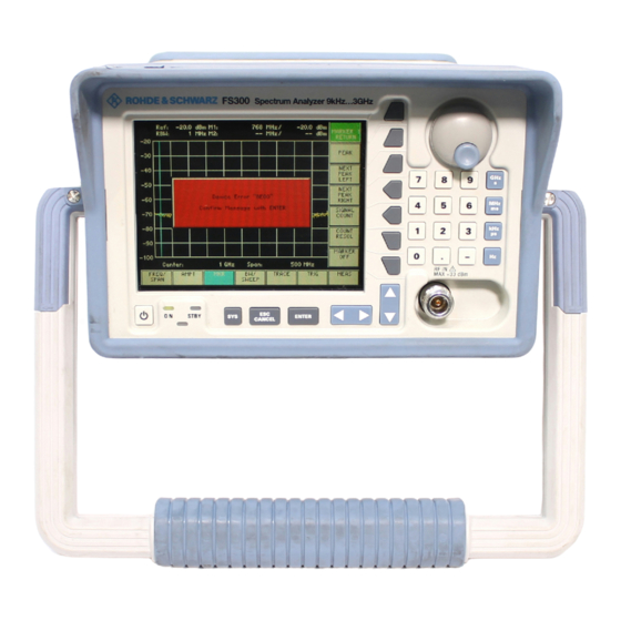
Front View R&S FS300 Control Elements Front View ON/STANDBY switch RF IN, RF input connector ON/STANDBY indicator Unit keys SYS key Rotary knob ESC/CANCEL key Numerical keys ENTER key Function keys Cursor keys 3 / 4 Screen Cursor keys 6 / 5 E-1007.9900.15... -
Page 41: Rear View
R&S FS300 Rear View Rear View Input connector for external trigger or AC line switch external gate signal Connector for external monitor Connector for external USB host Connector for external keyboard Output connector for USB device Input for external reference (10 MHz) (e. -
Page 42: Putting The R&S Fs300 Into Operation
Always be careful not to injure your fingers when installing the instrument and adjusting its handles. The R&S FS300 must be assembled on a firm, level surface only. The in- Setup instructions strument has a carrying handle which is also used for various setup options. - Page 43 R&S FS300 Setting up the Instrument Place the thumb and two fingers around the side-mounted setting lever Setting the handle and loosen it with a turning action. Slide the handle lengthwise while twisting it radially in steps of about 12°.
-
Page 44: Connecting The R&S Fs300 To The Ac Line
The power supply connector [17] is at the rear of the instrument. Connect the power cord to the AC line. Switching On the R&S FS300 The AC line is still connected to the R&S FS300 when the instrument is in the NOTE standby mode. -
Page 45: Function Test
“Error messages” ( 9-243). If the measurement trace does not appear on the screen shortly after booting, the sweep time may have been too long. In this case, reset the R&S FS300 NOTE by means of PRESET ( 6-153). -
Page 46: Connecting An External Keyboard
Connecting an External Keyboard ATTENTION Only connect the keyboard when the R&S FS300 is off or in the STANDBY mode, otherwise malfunctions may occur at a later date. You can connect an external PC keyboard via the 6-pin PS/2 KEYBOARD connector [21] on the R&S FS300’s rear panel. -
Page 47: Connecting A Usb Stick
Connecting a USB Stick ATTENTION To ensure that the USB stick is detected by the R&S FS300, the stick must be formatted in the FAT32 file system. You can connect an external USB stick to the USB device interface [16] at the rear of the R&S FS300. -
Page 48: Getting Started
Level and Frequency Measurements 4.1.1 Measurement Task The input stage of the R&S FS300 can be destroyed by overloads or DC ATTENTION components. If there is a possibility that the limits specified in the data sheet may be violated, the input must be protected with an attenuator and/or a DC block. -
Page 49: Measurement Procedure
Introduction is applied to the RF input [8]. The center frequency and the span are set manually. Perform the following steps: Measurement steps Reset the R&S FS300. • Press the key. • Select in the bottom menu bar using the cursor keys. -
Page 50: Manual Operating Concept
Chapter 6 contains an in-depth description of the menu functions. Chapter 7 contains note for remote control the R&S FS300 via a USB inter- face. Making Entries from the Keypad The R&S FS300 is operated using menus in conjunction with a keypad and a Introduction rotary knob. -
Page 51: Rotary Knob
R&S FS300 Making Entries from the Keypad 5.1.3 Rotary Knob As well as the numerical keys and the cursor keys, the rotary knob is also Function used to set parameters. The rotary knob has several functions: − Incrementing (turn clockwise) or decrementing (turn counter- clockwise) numerical instrument parameters using a specified step size. -
Page 52: Action Keys
− This key is for closing the entry field or selection field after data has been entered. The new value is set on the R&S FS300. NOTE: Pressing a unit key will also terminate the entry of setting data. −... -
Page 53: Screen Display
R&S FS300 Screen Display Screen Display The screen [13] provides on-going information about events and the parame- Introduction ters associated with the selected measurement functions. The display mode for the measurement results, the lettering of the function keys and the type of menu all depend on the current settings. -
Page 54: Diagram Area
Screen Display R&S FS300 5.2.1 Diagram Area The diagram area contains: Displays in the diagram area Measurement diagrams and the associated scales (h) and traces (e) Measured value displays, e. g. display line (d) and markers (c) Parameter field (b) and status displays (a) -
Page 55: Function Area
R&S FS300 Screen Display 5.2.3 Function Area When a menu is selected, the associated instrument functions are displayed Displaying the in the function area. current assignment for the function keys The displayed instrument functions are assigned to the seven function keys down the right-hand side of the screen. -
Page 56: Calling And Changing Menus
Calling and Changing Menus R&S FS300 Calling and Changing Menus Operating the R&S FS300 is menu-guided. All the menus used to set the Introduction measurement parameters and measurement functions are displayed in the menu area. The instrument functions associated with any menu you select are displayed in the function area. - Page 57 R&S FS300 Calling and Changing Menus Calling/quitting Press the function key in the menu. submenus The MARKER 1 submenu opens and the new functions are assigned to the function keys [12]. Press the function key in the submenu. The submenu is closed and the previous functions remain assigned to the function keys [12].
-
Page 58: Setting Parameters
Setting Parameters R&S FS300 Setting Parameters Parameters can be set in a number of ways: There is a choice of methods Direct selection of an instrument function (function key) Selecting settings from selection fields Entering numerical parameters in entry fields... -
Page 59: Selecting Settings
R&S FS300 Setting Parameters 5.4.2 Selecting Settings When you select a menu, a number of instrument functions are displayed in Introduction the function area. If certain function keys are then pressed, a selection field is displayed in the diagram area. You can then choose and activate any of the settings offered for selection. -
Page 60: Entering Numerical Parameters
Setting Parameters R&S FS300 5.4.3 Entering Numerical Parameters When you select a menu, a number of instrument functions will be displayed Introduction in the function area. If you press certain function keys, an entry field will be displayed in the diagram area. - Page 61 3a. Press a unit key [9], e. g. GHz, to terminate the entry. Terminating entries The R&S FS300 sets the value that has been set numerically using the new unit. The entry window is closed. 3b. Press the ENTER key [5] to terminate the entry.
-
Page 62: Entry Using The Cursor Keys And The Rotary Knob
Setting Parameters R&S FS300 5.4.3.2 Entry using the Cursor Keys and the Rotary Knob e. g. : Press the function key in the menu. Setting the span An entry field containing the current setting is displayed. 6-77) Using the cursor keys 3 and 4 [6], position the cursor on a decimal Entering place in the entry field. - Page 63 4b. Press the ENTER key [5] to terminate the entry. Terminating entries The R&S FS300 sets the value that has been set numerically but with the old unit. The entry window is closed. NOTE: If a parameter is unitless or always has the same unit, you can terminate the entry with the ENTER key or one of the unit keys.
-
Page 64: Overview Of All Menus And Functions
Overview of all Menus and Functions R&S FS300 Overview of all Menus and Functions 5.5.1 Spectrum Analyzer 5.5.1.1 FREQ/SPAN Menu Function key assignment Entering the center frequency 6-77) Entering the span 6-77) Entering the start frequency 6-78) Entering the stop frequency... -
Page 65: Ampt Menu
R&S FS300 Overview of all Menus and Functions 5.5.1.2 AMPT Menu Function key assignment Entering the reference level 6-88) Entering a level offset 6-89) Selecting the level display range 6-90) Selecting a unit for the level display 6-91) Setting the RF input attenuation manually... -
Page 66: Mkr Menu
Overview of all Menus and Functions R&S FS300 5.5.1.3 MKR Menu Function key assignment Open submenu: Activate marker 1 Quitting the submenu Place marker 1 on the trace maximum 6-99) Place marker 1 on the next trace maximum to the left... - Page 67 R&S FS300 Overview of all Menus and Functions Open submenu: Marker measurement functions Quitting the submenu Measuring noise power density 6-110) Measuring signal bandwidth 6-111) Bring display line up on screen 6-113) Open submenu: Search criterion of functions NEXT PEAK LEFT/RIGHT...
-
Page 68: Bw/Sweep Menu
Overview of all Menus and Functions R&S FS300 5.5.1.4 BW/SWEEP Menu Function key assignment Setting the resolution bandwidth manually 6-122) Activating automatic resolution bandwidth setting 6-122) Setting the video bandwidth manually 6-123) Activating automatic video bandwidth setting 6-123) Open submenu:... -
Page 69: Trace Menu
R&S FS300 Overview of all Menus and Functions 5.5.1.5 TRACE Menu Function key assignment Open submenu: Selecting the active trace Quitting the submenu Turning on and activating Trace 1 6-132) Turning on and activating Trace 2 6-132) Trace display mode: Overwrite mode 6-134) Trace display mode: Min./Max. -
Page 70: Trig Menu
Overview of all Menus and Functions R&S FS300 5.5.1.6 TRIG Menu Function key assignment Free-running measurements 6-141) Open submenu: Triggering by an external TTL signal Quitting the submenu Triggering on positive-going edge 6-144) Triggering on negative-going edge 6-144) Triggering by the display level... -
Page 71: Meas Menu
R&S FS300 Overview of all Menus and Functions 5.5.1.7 MEAS Menu Function key assignment Open submenu: Measure the power in the time domain (ZERO SPAN) Quitting the submenu Output the peak value within the section 6-147) Output the mean value within the section... -
Page 72: System Functions
Overview of all Menus and Functions R&S FS300 5.5.2 SYSTEM Functions 5.5.2.1 PRESET Menu Function key assignment Calls an instrument default setting 6-154) Selects an instrument default setting 6-154) 5.5.2.2 STATUS Menu Function key assignment Displaying the current instrument setting 6-155) 5.5.2.3... -
Page 73: Info Menu
R&S FS300 Overview of all Menus and Functions 5.5.2.6 INFO Menu Function key assignment Displays module data 6-176) Displays instrument statistics 6-176) Displays system messages 6-177) Operating manual, 02/2006 5-73 E-1007.9900.15... -
Page 74: Using The R&S Fs300
CLEAR/WRITE Trace Trigger FREE RUN Trigger Marker 1 and marker 2 Markers The factory default setting is stored in non-volatile memory in the R&S FS300 NOTE and can be reloaded at any time ( 6-153). E-1007.9900.15 6-74 Operating manual, 02/2006... -
Page 75: Spectrum Analyzer
The time characteristic of the amplitude at the set frequency is displayed in zero span. When the R&S FS300 is switched on and the selftest passed, the spectrum User interface analyzer’s user interface is activated. The following is displayed on the... -
Page 76: Selecting The Frequency Span (Freq/Span Menu)
Spectrum Analyzer R&S FS300 6.2.1 Selecting the Frequency Span (FREQ/SPAN Menu) Use the FREQ/SPAN menu to specify the frequency range. What the settings are for • Selecting the Select the menu using the 3 or 4 cursor key [6]. FREQ/SPAN... -
Page 77: Entering The Center Frequency And The Span
R&S FS300 Spectrum Analyzer 6.2.1.1 Entering the Center Frequency and the Span If you know the frequency of the signal you want to measure, you can set the x axis of the diagram area accordingly. Enter the signal frequency as the center frequency (CENTER) and specify a SPAN. -
Page 78: Entering The Start Frequency And The Stop Frequency
Spectrum Analyzer R&S FS300 6.2.1.2 Entering the Start Frequency and the Stop Frequency If you want to analyze a specific frequency range, you can enter a start fre- quency and a stop frequency. The frequency range is shown along the x axis of the diagram area. -
Page 79: Entering The Step Width Of The Center Frequency
Using the CF STEP SIZE submenu, you can set any step size of the rotary What the settings knob you want or have the R&S FS300 set a step size that is a function of the are for measurement parameters. -
Page 80: Setting The Step Size
Spectrum Analyzer R&S FS300 6.2.1.3.1 Setting the Step Size If you want to examine the frequency spectrum at certain intervals, you can Setting the step size enter the value of your choice for the step size of the rotary knob. -
Page 81: Frequency-Axis Display Modes
R&S FS300 Spectrum Analyzer 6.2.1.4 Frequency-Axis Display Modes The frequency axis (x axis) can be displayed in a number of ways. Using the What the settings SPAN SETTINGS submenu, you can display the whole frequency range, are for zoom in on subranges of the frequency axis or project the diagram area onto the whole of the screen, if and when you require. -
Page 82: Displaying The Whole Frequency Range
If you do not know the frequency of the signal to be investigated, you can display the R&S FS300’s whole frequency range along the x axis of the dia- gram area. You can then systematically reduce the span to the appropriate size ( 6-77). -
Page 83: Switching Over To The Zero Span
R&S FS300 Spectrum Analyzer 6.2.1.4.2 Switching over to the ZERO SPAN The amplitude of a particular signal component in the frequency spectrum can be displayed as a function of time. To activate this mode, enter the fre- quency of the signal component as the center frequency. You can then define the x axis to be the time axis. -
Page 84: Zoom Functions
Spectrum Analyzer R&S FS300 6.2.1.4.3 ZOOM Functions If you want to increase or decrease the size of the screen window to analyze traces, you can zoom onto sections of the span or fill the whole screen with the current screen window. -
Page 85: Signal Tracking
R&S FS300 Spectrum Analyzer 6.2.1.5 Signal Tracking When signal tracking is selected, the center frequency of the R&S FS300 is What the settings continually set to the frequency of the signal with most power. This means are for that a signal whose frequency is changing slowly in comparison with the sweep time can be kept in the center of the screen. - Page 86 Spectrum Analyzer R&S FS300 6.2.1.5.1 Activating Signal Tracking If the frequency of the signal being analyzed is continually varying, you can use this function to obtain a display that appears to be stationary. The power of signals of this kind can then be measured over long periods.
-
Page 87: Setting The Level Axis And The Rf Input (Ampt Menu)
R&S FS300 Spectrum Analyzer 6.2.2 Setting the Level Axis and the RF Input (AMPT Menu) From the AMPT menu, you can define the y axis of the measurement dia- What the settings gram as the level axis. You can also specify the attenuation of the RF input. -
Page 88: Entering The Reference Level
Spectrum Analyzer R&S FS300 6.2.2.1 Entering the Reference Level The upper diagram limit is specified with the reference level. REF LEVEL The currently activated unit is used as the unit for reference level entries ( NOTE 6-91). The default setting is “dBm”. -
Page 89: Entering A Level Offset
R&S FS300 Spectrum Analyzer 6.2.2.2 Entering a Level Offset If you have connected external attenuators or amplifiers between the DUT and the RF input, you can enter a level offset to adjust the level display. The level offset is added to the reference level. -
Page 90: Selecting The Level Display Range
Spectrum Analyzer R&S FS300 6.2.2.3 Selecting the Level Display Range Use the level display range to define the “visible” level range and set the measurement diagram scale. RANGE Levels can be displayed using either logarithmic or linear scales. The lettering of the grid lines is automatically adapted. -
Page 91: Selecting The Level Display Unit
R&S FS300 Spectrum Analyzer The level display range uses the currently activated unit ( 6-91). NOTE 6.2.2.4 Selecting the Level Display Unit To make it easier to analyze results, you can display levels in dBm, dBmV, dBµV, mV and mW. - Page 92 Spectrum Analyzer R&S FS300 Log display/RANGE in xV or xW (The letter x is a wildcard character for the letters m, mV or µV.) If a mV or mW has been selected for UNIT, only the reference level is dis- played in the selected unit.
-
Page 93: Setting The Rf Input Attenuation Manually
R&S FS300 Spectrum Analyzer 6.2.2.5 Setting the RF Input Attenuation Manually In the default setting, the input attenuation is coupled to the reference level. In most cases, this is the setting that will be used because it prevents the input stages from being overdriven and so, consequently, any incorrect measure- ments. -
Page 94: Setting The Rf Input Attenuation Automatically
6.2.2.6 Setting the RF Input Attenuation Automatically The input attenuation should be set automatically to prevent the R&S FS300’s input mixer from being overloaded. There are three RF input modes you can choose from (coupling between reference level and input attenuation) to op-... - Page 95 R&S FS300 Spectrum Analyzer Activating the auto- Press the function key in the menu. matic input A selection field containing the available settings is displayed. The de- attenuation fault setting is NORMAL. setting mode Using the rotary knob [10] select a criterion for autosetting the input attenuation.
-
Page 96: Selecting The Setting High Sensitivity
RBW display. You can switch the input attenuation of the analyzer to 0 dB by means of SET HIGH SENS. To ensure that the R&S FS300 is not overdriven, the level at the NOTE analyzer input must not exceed the reference level that has been set. ( 88). -
Page 97: Signal Analysis Using Marker Functions (Mkr Menu)
R&S FS300 Spectrum Analyzer 6.2.3 Signal Analysis using Marker Functions (MKR Menu) Using the MKR menu, you can position markers on any point on the trace to What the settings read off any levels or level differences of interest. The measured values indi-... -
Page 98: Activating Marker 1
Spectrum Analyzer R&S FS300 6.2.3.1 Activating Marker 1 From the MARKER 1 submenu, you can activate a marker and position it on What the settings the trace. All the current level and frequency values (marker values) are dis- are for played. -
Page 99: Reading Off Measured Values With Marker 1
R&S FS300 Spectrum Analyzer 6.2.3.1.1 Reading off Measured Values with Marker 1 You can position marker 1 on the trace to read off specific levels and fre- quencies (marker values). Activating marker 1 Press the function key in the submenu. - Page 100 Spectrum Analyzer R&S FS300 Change the marker position with rotary knob [10]. Scrolling marker 1 The current M1 marker values are displayed in the parameter field. De-activating • Press the function key in the submenu. marker 1 Marker 1 (and marker 2, if activated) disappears from the diagram area and the M1 (M2) marker values are blanked out.
-
Page 101: Frequency Measurements Using The Frequency Counter
R&S FS300 Spectrum Analyzer 6.2.3.1.2 Frequency Measurements using the Frequency Counter The normal marker indicates the frequency represented by the pixel on which it is placed. The measurement uncertainty is relatively large because the number of pixels is limited to 250. -
Page 102: Activating Marker 2
Marker 2 can be used either as a normal marker (NORM) or as a delta marker (DELTA). The delta marker function expands the R&S FS300’s analy- sis capability and can be used as a basis for a variety of measurement tech- niques ( 6-145). -
Page 103: Reading Off Measured Values With Marker 2
R&S FS300 Spectrum Analyzer 6.2.3.2.1 Reading off Measured Values with Marker 2 To read off specific levels, you can activate marker 2 as a normal marker (in addition to marker 1) and position it on the trace. The current level and fre- quency can be displayed in this way (M2 marker values). -
Page 104: Reading Off Level Differences
Spectrum Analyzer R&S FS300 6.2.3.2.2 Reading off Level Differences You can define marker 2 as a delta marker to read off level differences from the trace. The level difference between marker 2 and a reference point is displayed. Marker 1 ( 6-98) or reference values that have been set manually 6-117) can be used as reference points. -
Page 105: Accepting Marker Values As Settings
R&S FS300 Spectrum Analyzer 6.2.3.3 Accepting Marker Values as Settings From the MKR> submenu, you can accept the marker values of the active What the settings marker as settings for level, frequency or frequency steps. are for The step size used to enter the center frequency with the help of the rotary knob can also be the marker frequency. -
Page 106: Moving Trace Sections In The Measurement Diagram
Spectrum Analyzer R&S FS300 6.2.3.3.1 Moving Trace Sections in the Measurement Diagram If you want to analyze a section of the trace more closely, you can change ist location within the measurement diagram using the active marker. The marker frequency becomes the center frequency and the marker level be- comes the upper diagram boundary. - Page 107 R&S FS300 Spectrum Analyzer In the time-domain mode (ZERO SPAN), the function key is not avail- NOTE able. Setting the Press the function key in the submenu. reference level to The current marker level is set as the reference level ( 6-88).
-
Page 108: Setting The Step Size To The Marker Frequency
Spectrum Analyzer R&S FS300 6.2.3.3.2 Setting the Step Size to the Marker Frequency If you set the step size to the marker frequency, you will find that you can quickly jump back to the start frequency when you are stepping through the frequency spectrum with the help of the rotary knob. -
Page 109: Marker Measurement Functions
R&S FS300 Spectrum Analyzer 6.2.3.4 Marker Measurement Functions From the MKR FCTN submenu, using the markers, you can select certain What the settings spectral components of the input signal to measure the noise power density are for and the signal bandwidth. - Page 110 Spectrum Analyzer R&S FS300 6.2.3.4.1 Measuring the Noise Power Density The R&S FS300 allows you to measure the noise power density at the active marker position. Turn on the markers ( 6-98, 6-102). Measuring noise power density Position the activated marker ( 6-99, 6-103) as desired.
-
Page 111: Measuring The Filter Or Signal Bandwidth
R&S FS300 Spectrum Analyzer 6.2.3.4.2 Measuring the Filter or Signal Bandwidth If you want to measure the bandwidth of a certain signal spectrum shown in the measurement diagram, you can do this with the N dB DOWN function. Two lines one of which is n dB down on the active reference marker are dis- played on the screen [13]. - Page 112 Spectrum Analyzer R&S FS300 Terminating the • Press the function key in the submenu. measurement The signal or filter bandwidth measurement is terminated and the tempo- rary markers T1 and T2 disappear from the screen. The M2 marker val- ues are again displayed in the parameter field.
-
Page 113: Activating A Display Line
R&S FS300 Spectrum Analyzer 6.2.3.5 Activating a Display Line If you want to observe whether a signal exceeds or falls below a certain level you can activate a horizontal display line in the measurement diagram and adjust its position. Activating the... -
Page 114: Setting The Search Criterion Of Functions Next Peak Left/Right
Spectrum Analyzer R&S FS300 6.2.3.6 Setting the Search Criterion of Functions NEXT PEAK LEFT/RIGHT From the MARKER SETTINGS submenu, you can set the search criterion of What the settings functions NEXT PEAK LEFT/RIGHT. The PEAK EXCURSION function key are for enables –... -
Page 115: Entering The Peak Excursion
R&S FS300 Spectrum Analyzer 6.2.3.6.1 Entering the Peak Excursion If NEXT PEAK LEFT or NEXT PEAK RIGHT is selected, these functions search for the next relative maximum left or right of the current marker posi- tion irrespective of the current signal amplitude. When the signal level de- creases for a definite amount, the peak excursion, to either side of the maxi- mum a relative maximum is given. - Page 116 Spectrum Analyzer R&S FS300 With this setting, NEXT PEAK LEFT and NEXT PEAK RIGHT will not find any 50 dB signal, as the signal level does not decrease by more than 48 dB to either peak excursion side of any signal.
-
Page 117: Setting Reference Points For Level-Difference Measurements
From the REF FIXED submenu, you can define any reference point within the What the settings R&S FS300’s measurement range. You can use this point as a fixed refer- are for ence for level-difference measurements using the delta marker ( 6-104). -
Page 118: Manual Entry Of Reference Points
Spectrum Analyzer R&S FS300 6.2.3.7.1 Manual Entry of Reference Points There are two methods you can use to find level differences from the trace. The first method is to define a reference point on the trace using marker 1 ( 6-98). - Page 119 R&S FS300 Spectrum Analyzer 4a) Frequency-domain display mode (SPAN > 0, 6-76): Entering a reference point frequency • Press the function key in the submenu. An entry field containing the current setting (frozen marker frequency)is displayed. • Enter a new value ( 5-60).
- Page 120 Spectrum Analyzer R&S FS300 Activating M1 • Press the function key in the submenu. marker values as The reference values (R) disappear from the screen and the M1 marker reference points values are again activated. Marker 1 is positioned on the last reference point frequency on the trace and can again be moved, e.
-
Page 121: Setting The Bandwidths And The Sweep Time (Bw/Sweep Menu)
R&S FS300 Spectrum Analyzer 6.2.4 Setting the Bandwidths and the Sweep Time (BW/SWEEP Menu) You can set the resolution bandwidth (RBW), the video bandwidth (VBW) and What the settings the sweep time using the BW/SWEEP menu. are for The parameters determine the measurement procedure and can be coupled as a function of the SPAN or set independently. -
Page 122: Setting The Resolution Bandwidth
To make certain measurements, it may be necessary to set the resolution bandwidth and the span independ- ently. With the R&S FS300, you can manually set resolution bandwidths from 200 Hz to 1 MHz in a 1, 2, 3, 5, 10 sequence. -
Page 123: Setting The Video Bandwidth
• Press the function key in the menu. automatic video The R&S FS300’s video bandwidth is set to three times the resolution bandwidth bandwidth. If the resolution bandwidth is changed, the video bandwidth is setting adjusted automatically. Within the permissible setting range, the video bandwidth is set to the value that is closest to three times the value of the resolution bandwidth. -
Page 124: Rbw, Vbw And Span Coupling Ratio
Spectrum Analyzer R&S FS300 6.2.4.3 RBW, VBW and SPAN Coupling Ratio You can set the coupling ratio between the video bandwidth, the resolution What the settings bandwidth and the frequency display span using the COUPLING RATIO sub- are for menu. -
Page 125: Changing The Coupling Ratio Rbw/Vbw
Activating the • Press the function key in the submenu. default setting for The R&S FS300‘s video bandwidth is set to three times the resolution the coupling ratio bandwidth. Operating manual, 02/2006 6-125 E-1007.9900.15... -
Page 126: Switching Over The Coupling Rbw/Span To Low Noise
Spectrum Analyzer R&S FS300 6.2.4.3.2 Switching Over the Coupling RBW/SPAN to Low Noise You can change the automatic coupling between frequency display span (SPAN) and resolution bandwidth (RBW) by means of the RBW/SPAN LOW NOISE function. This makes it possible to increase the measurement sensitivity of the analyzer in comparison to the normal setting. -
Page 127: Setting The Sweep
R&S FS300 Spectrum Analyzer 6.2.4.4 Setting the Sweep You can select the type of sweep and the sweep time from the SWEEP sub- What the settings menu. are for Selecting the • Press the function key in the menu. SWEEP... -
Page 128: Selecting The Frequency Sweep
Spectrum Analyzer R&S FS300 6.2.4.4.1 Selecting the Frequency Sweep Frequency sweep is the process where the resolution filter covers a defined frequency range. Sweeps may be performed continuously (CONT SWEEP) or once (SIN- GLE SWEEP). Starting a • Press the function key in the submenu. -
Page 129: Setting The Sweep Time
(VBW). The sweep time is automatically ad- justed if either the span, the RBW or the VBW are changed. The R&S FS300 always selects the shortest possible sweep time consis- tent with valid results. The maximum level error trade-off for a longer sweep time is <... -
Page 130: Measured-Value Display (Trace Menu)
Spectrum Analyzer R&S FS300 6.2.5 Measured-Value Display (TRACE Menu) Using the TRACE menu, you can apply various display modes to the input- What the settings signal results. Two traces (Trace 1, Trace 2) are provided for this purpose. are for •... -
Page 131: Selecting The Active Trace
R&S FS300 Spectrum Analyzer 6.2.5.1 Selecting the Active Trace Via the SELECT TRACE submenu, you can activate a second trace and se- What the settings lect the current trace (Trace 1, Trace 2) to which all the following settings will are for be applied. -
Page 132: Activating Traces
6-134), is displayed in the top left of the diagram area in the trace colour: When the R&S FS300 is turned on, Trace 2 is turned off. When the trace is Turning on called for the first time, the CLEAR/WRITE display mode is set. - Page 133 R&S FS300 Spectrum Analyzer Turning off Press the function key in the submenu. Trace 2 Trace 2 is now active. Press the function key in the menu. Trace 2 is blanked out. Press the function key in the submenu. Trace 1 is activated and Trace 2 is turned off.
-
Page 134: Displaying The Active Trace
After a measurement has been performed, the trace can be frozen (VIEW) or blanked out (BLANK). When the R&S FS300 is switched on, Trace 1 is active and is displayed in Displaying the CLEAR/WRITE display mode. - Page 135 Press the ENTER key [5] to close the selection field. The MIN/MAX function is activated. This means that, after every sweep, the R&S FS300 only transfers the new measured value to the measured value memory if it is smaller/greater than the previous value. The current display mode , e.
- Page 136 Spectrum Analyzer R&S FS300 Press ENTER key [5] to close the entry field. The new setting is saved. Averaging is started and the result is dis- played. The current display mode AVG is shown in the top left of the diagram area.
-
Page 137: Trace Difference Function
R&S FS300 Spectrum Analyzer 6.2.5.3 Trace Difference Function function key is available only if both traces are turned on ( NOTE 131). You can activate the difference function for two traces (Trace 1, Trace 2) from What the settings the MATH submenu and use this function to analyze the input signal. - Page 138 6.2.5.3.1 Activating the Trace Difference Function You can use the R&S FS300’s MATH function to directly determine differ- ences between signals by forming the difference of two traces. The new ref- erence for the difference trace is in the center of the measurement diagram (50 %).
- Page 139 R&S FS300 Spectrum Analyzer Repositioning Press the function key in the submenu. Trace 1 (result) A reference line is displayed in the middle of the current diagram area. The text “SCROLL or press ENTER” is displayed to tell you that the trace can be moved up or down.
-
Page 140: Triggering Measurements (Trig Menu)
Spectrum Analyzer R&S FS300 6.2.6 Triggering Measurements (TRIG Menu) From the TRIG menu, you can select a variety of trigger sources. You can set What the settings the trigger edge and the measurement time for external trigger signals (TTL). are for •... -
Page 141: Internal Trigger Sources
R&S FS300 Spectrum Analyzer 6.2.6.1 Internal Trigger Sources Depending on the measurement, you can use a variety of criteria for trigger- ing measurements in the frequency domain (SPAN > 0) or in the time domain (ZERO SPAN). Free-running triggering Triggering by the display level (only in the time domain, ZERO SPAN) - Page 142 Spectrum Analyzer R&S FS300 This makes it possible to perform synchronized measurements on video sig- Triggering by nals, for example, which can even be triggered using the frequency of the AC the AC line line. frequency • Press the function key in the menu.
-
Page 143: External Trigger Sources
R&S FS300 Spectrum Analyzer 6.2.6.2 External Trigger Sources From the EXTERNAL submenu, you can activate an external TTL signal and What the settings specify the trigger edge for triggering measurements. are for Selecting the • Press the function key in the menu. -
Page 144: Setting The Trigger Edge For External Ttl Signals
Setting the Trigger Edge for External TTL Signals For certain measurements, you can use an external TTL signal (squarewave signal) as a trigger. The trigger period is user-selectable. The R&S FS300 allows you to set triggering on a rising or on a falling edge of the squarewave. -
Page 145: Measurement Functions (Meas Menu)
R&S FS300 Spectrum Analyzer 6.2.7 Measurement Functions (MEAS Menu) From the MEAS menu, you can measure the power in the time domain What the settings (ZERO SPAN) as well as the third-order intercept point. are for • Selecting the Select the menu with the 3 or 4 cursor key [6]. -
Page 146: Measuring The Power In The Time Domain
Spectrum Analyzer R&S FS300 6.2.7.1 Measuring the Power in the Time Domain From the TIME DOMAIN PWR submenu, you can determine the trace section What the settings for which the power measurement is to be performed. You can measure ei- are for ther the mean power (MEAN) or the peak power (PEAK). -
Page 147: Measuring The Power
6.2.7.1.1 Measuring the Power By using the "Time Domain Power" measurement function, the R&S FS300 determines in the time domain (ZERO SPAN) the power of the signal by inte- grating the pixels within the selected section. This allows you to measure the power of TDMA signals, for example, during the transmission phase or during the mute phase. - Page 148 Spectrum Analyzer R&S FS300 Activating the Press the function key in the submenu. measurement The maximum power is measured within the limit lines T1 and T2 and displayed in the parameter field (PEAK:). In the default setting, these are the left (T1) and the right (T2) limit lines of the measurement diagram.
- Page 149 R&S FS300 Spectrum Analyzer Changing the Press the function key in the submenu. measurement range A limit line is inserted at the left side of the diagram. The "SCROLL or (limit lines) press ENTER" display shows you that the limit lines can be scrolled to the left or to the right.
-
Page 150: Measuring The Third-Order Intercept Point
/2 + P When the TOI function is set and the markers are set to the input signals, the R&S FS300 automatically measures the intermodulation products and dis- plays the value calculated for the intercept point. Set markers 1 and 2 to the two input signals ( 6-98, 6-102). -
Page 151: System Functions (Sys Key)
All current settings can be called so that they can be viewed at a glance, and saved for use at a later date, a selftest can be run on the R&S FS300 and the system settings configured. Furthermore, the R&S FS300 can be switched over from remote control to local mode. - Page 152 SYSTEM Functions (SYS Key) R&S FS300 Menus for system and service functions Selects and calls the instrument‘s default setting 6-153 Displays the current instrument settings 6-155) Saves and loads user-defined settings 6-156) System settings 6-165) Service functions 6-174) System information 6-175) E-1007.9900.15...
-
Page 153: Instrument Default Setting (Menu Preset)
R&S FS300 SYSTEM Functions (SYS Key) 6.3.1 Instrument Default Setting (Menu PRESET) From the PRESET menu, you can specify a user-defined instrument setting What the settings as the instrument default setting and directly call it. are for Press the SYS key [3]. -
Page 154: Selecting And Calling The Instrument Default Setting
6.3.1.1 Selecting and Calling the Instrument Default Setting When you switch on the R&S FS300, those settings that were valid when the R&S FS300 was last switched off are restored. The R&S FS300 also lets you save and call user-defined instrument settings. -
Page 155: Displaying The Current Instrument Setting (Status Menu)
R&S FS300 SYSTEM Functions (SYS Key) 6.3.2 Displaying the Current Instrument Setting (STATUS Menu) From the STATUS menu, you can display an overview of the principal current What the settings instrument settings. are for Press the SYS key [3]. Selecting the... -
Page 156: User-Defined Settings (File Menu)
SYSTEM Functions (SYS Key) R&S FS300 6.3.3 User-Defined Settings (FILE Menu) You can save user-defined settings and waveforms and load them when re- What the settings quired from the FILE menu. You can also print out a screenshot. are for Press the SYS key [3]. -
Page 157: Saving And Loading User-Defined Settings
R&S FS300 was last switched off are restored. The R&S FS300 also lets you save and load user-defined settings. You can save 10 different settings (SAVE 1 to 10). When the R&S FS300 is delivered, the factory settings are loaded in the SAVE memory locations. - Page 158 SYSTEM Functions (SYS Key) R&S FS300 Loading user- Press the function key in the menu. defined settings A table containing the available settings is displayed (memory locations). Select a setting with the 5 or 6 cursor key [7]. Note: The “Factory” memory location contains the factory setting ( 74).
-
Page 159: Saving And Loading Waveforms
R&S FS300 was last switched off are restored. The R&S FS300 also lets you save and load waveforms. You can save 5 traces (WAVE 1 to 5). When the R&S FS300 is delivered, the WAVE memory locations are empty. Set up the R&S FS300 for the measurement you want to perform ( Saving waveforms 74). - Page 160 SYSTEM Functions (SYS Key) R&S FS300 Loading waveforms Press the function key in the menu. A table containing the available settings is displayed (memory locations). Select a setting with the 5 or 6 cursor key [7]. The EMPTY memory location contains no waveform.
-
Page 161: Printing Out A Screenshot
6.3.3.3 Printing out a Screenshot The R&S FS300 prints out (printer) or saves (USB stick) a current screenshot when you press the SYS key and an overview of the principal current instru- ment settings. A printer with a USB device connector or a USB stick is re- quired. - Page 162 SYSTEM Functions (SYS Key) R&S FS300 Connect a printer to the USB device connector [16]. Printing out a screenshot Select a printer for the output unit ( 6-161). Press the function key in the menu. A table containing the available parameters is displayed.
- Page 163 R&S FS300 SYSTEM Functions (SYS Key) Connect the USB stick to the USB device connector [16]. Saving the screen- shot as a bitmap Select the USB stick for the output unit ( 6-161). (.bmp) in the USB Press the function key in the stick menu.
- Page 164 SYSTEM Functions (SYS Key) R&S FS300 Connect the USB stick to the USB device connector [16]. Saving the wave- form data as an Press the function key in the menu. ASCII file (.asc) in the USB stick A table containing the available parameters is displayed.
-
Page 165: System Settings (Config Menu)
R&S FS300 SYSTEM Functions (SYS Key) 6.3.4 System Settings (CONFIG Menu) You can configure the general system parameters for time/date, reference What the settings source, instrument interface and screen saver from the CONFIG menu. are for Press the SYS key [3]. -
Page 166: Setting The Date And Time Of Day
SYSTEM Functions (SYS Key) R&S FS300 6.3.4.1 Setting the Date and Time of Day When you save a setting, it is time-stamped using the time provided by the internal real-time clock ( 6-157). When you set the internal real-time clock, you can choose between two date and time display format options and modify the parameters. - Page 167 R&S FS300 SYSTEM Functions (SYS Key) Setting Press the function key in the menu. the date A table containing the available parameters is displayed. Select the DATE parameter with the 5 or 6 cursor key [7]. Press the ENTER key [5].
-
Page 168: Selecting An Internal Or External Reference Source
6.3.4.2 Selecting an Internal or External Reference Source The R&S FS300 acting as the frequency standard for all internal oscillators can use the internal reference source (internal) or an external reference source (external). A 10 MHz crystal oscillator is used as the internal refer- ence source. -
Page 169: Configuring The Instrument Interfaces
PC. When you press the SYS key [3], the R&S FS300 can be switched to “lo- cal mode” at any time. The PC and the R&S FS300 are thus physically disconnected. - Page 170 If EXTERNAL is set, the USB master switch is in the “remote control” mode and the R&S FS300 can only be controlled via a PC. When you press the SYS key [3], the R&S FS300 can be switched again to “local mode” at any time, for example for changing settings. Reactivate the EXTERNAL setting to switch the R&S FS300 again to “remote con-...
-
Page 171: Setting The Screen Saver Mode
SYSTEM Functions (SYS Key) 6.3.4.4 Setting the Screen Saver Mode The R&S FS300 has a screen-saver function that turns off the screen [13] after a certain time. There are a number of timing options for screen turn-off: none The screen is always on. - Page 172 With the “picture” setting, the following message is displayed on the screen with the R&S FS300 in remote-control mode: With remote control, the local control mode of the R&S FS300 is deactivated and can only be reactivated by pressing the SYS key [3] on the front panel.
-
Page 173: Selecting An Internal Or External Monitor
R&S FS300 SYSTEM Functions (SYS Key) 6.3.4.5 Selecting an Internal or External Monitor Screen display is possible via the internal monitor or an external monitor. intern Screen display is via the built-in colour TFT display. extern Screen display is via the connected monitor. -
Page 174: Service Functions (Service Menu)
Performs a selftest 6-174) 6.3.5.1 Performing Selftests The R&S FS300 can perform a module selftest. If there is a fault, the R&S FS300 itself is capable of localizing the defective module. Starting Press the function key in the menu. -
Page 175: System Information (Info Menu)
R&S FS300 SYSTEM Functions (SYS Key) 6.3.6 System Information (INFO Menu) You can obtain information such as module data, instrument statistics and What the settings system messages from the INFO menu. are for Press the SYS key [3]. Selecting the... -
Page 176: Displaying Module Data
SYSTEM Functions (SYS Key) R&S FS300 6.3.6.1 Displaying Module Data You can display the serial number of the modules installed in the R&S FS300. Calling • Press the function key in the menu. module data A table listing the current modules and the serial number is displayed. -
Page 177: Displaying System Messages
SYSTEM Functions (SYS Key) 6.3.6.3 Displaying System Messages You can display the most recent R&S FS300 system messages in their order of occurrence. Operating errors are neither saved nor displayed. System messages help the service personnel to analyze the instrument and handle errors, and should therefore only be deleted by them. - Page 178 SYSTEM Functions (SYS Key) R&S FS300 Deleting system Press the function key in the menu. messages (only for The table of current system messages is displayed. service Select the first line with the 5 or 6 cursor key [7]. Press the ENTER key [5].
-
Page 179: Remote Control/Pc Software Fs300-K1
The PC Software R&S FS300-K1 allows convenient operation of the R&S Performance fea- FS300 by remote control via a PC. All the functions of the spectrum ana- tures lyzer are supported. In addition, you can create test reports on your PC. -
Page 180: Installation And Configuration
The PC software is installed in two steps. Firstly the remote control program Introduction for the R&S FS300 is installed. The R&S FS300 must not be connected at this time. Secondly the drivers are installed; at this time the instrument has to be connected. - Page 181 R&S FS300 Installation and Configuration Click <Next> to continue the installation. Click <Browse> to assign a new directory if you wish to install the pro- gram in another directory than proposed. Click <Next> to continue the installation. Operating manual, 02/2006 7-181 E-1007.9900.15...
- Page 182 Installation and Configuration R&S FS300 Click <Next> to continue the installation. Installation begins and the data are transferred to the PC. Please wait a moment. Click <Finish> to successfully complete the installation. Click <Yes> to restart the computer. E-1007.9900.15 7-182...
-
Page 183: Installing The Device Drivers
7.2.1.2 Installing the Device Drivers 7.2.1.2.1 Installing Steps for Windows™ 2000 R&S FS300 is connected to the PC via the USB interface. The connection Connecting R&S cable has two plug types. Plug A is connected to the computer ( computer FS300 to the PC manual) and plug B is connected to the R&S FS300 (... - Page 184 Installation and Configuration R&S FS300 Click <Next> to continue the installation. Installing device drivers Select Search for a suitable driver for my device and click <Next> to continue the installation. E-1007.9900.15 7-184 Operating manual, 02/2006...
- Page 185 R&S FS300 Installation and Configuration If there is already installed a driver for the R&S FS300 on your system, the Windows Hardware Wizard may give you a selection of already in- stalled drivers: Please select “rssi.inf” and click <Next> to continue the installation.
- Page 186 This is followed by the installation of the device driver for the Rohde & Schwarz Power Supply. Windows generally "remembers" all the nec- essary information when installing the Spectrum Analyzer R&S FS300 and installs the Rohde & Schwarz Power Supply without a query. How- ever, depending on the system, the installation assistant might be acti- vated.
-
Page 187: Installing Steps For Windows™ Xp
Create now the program version for specific instrument ( 7-192). 7.2.1.2.2 Installing Steps for Windows™ XP R&S FS300 is connected to the PC via the USB interface. The connection Connecting R&S cable has two plug types. Plug A is connected to the computer ( computer FS300 to the PC manual) and plug B is connected to the R&S FS300 (... - Page 188 Installation and Configuration R&S FS300 If the R&S FS300 is not automatically recognized, check that the USB master switch of the R&S FS300 is at AUTO ( 6-169). Select Install the software automatically and click <Next> to continue Installing device the installation.
- Page 189 R&S FS300 Installation and Configuration If there is already installed a driver for the R&S FS300 on your system, the Windows Hardware Wizard may give you a selection of already in- stalled drivers: Please select “rssi.inf” and click <Next> to continue the installation.
- Page 190 This is followed by the installation of the device driver for the Rohde & Schwarz Power Supply. Windows generally "remembers" all the nec- essary information when installing the Spectrum Analyzer R&S FS300 and installs the Rohde & Schwarz Power Supply without a query. How- ever, depending on the system, the installation assistant might be acti- vated.
- Page 191 R&S FS300 Installation and Configuration The drivers are now correctly installed and this can be checked using the device manager. Create now the program version for specific instrument ( 7-192). Operating manual, 02/2006 7-191 E-1007.9900.15...
-
Page 192: Connecting The Pc-Software With The R&S Fs300
R&S FS300 7.2.2 Connecting the PC-Software with the R&S FS300 Due to the USB-Technology which is used in the R&S FS300, more than one Introduction instrument in the 300 Series can be connected with a PC at the same time. -
Page 193: Creating The Program Version
(0000xxxxxx). In II click <Exit> to close the service program. After correctly creating the program version, the option FS300 0000xxxxxx is available in the Win- dows™ start-up menu Start\Programs\Rohde & Schwarz\Series300. Now the program FS300 0000xxxxxx can be started ( 7-198). -
Page 194: Uninstalling The Pc Software
Installation and Configuration R&S FS300 7.2.3 Uninstalling the PC Software Place the CD ROM, which came with the product, in the installation drive. Installation steps for The autorun function automatically initiates installation. Alternatively you Windows™ 2000 may also initiate the installation in the start menu of Windows™... -
Page 195: Update Pc Software
R&S FS300 Installation and Configuration 7.2.4 Update PC Software Old versions of the PC-Software can be updated with the Series 300 Soft- Introduction ware Manager. Therefore the old version has to be uninstalled ( 7-194). The new version can then be installed from the CD-ROM ( 7-180). - Page 196 Click in II on <Update>, to update the displayed link. Updating the link Click in II on <Exit>, to shut down the service program. The updated connection FS300 0000xxxxxx is displayed in the Windows™ Start Menu Start\Programme\Rohde & Schwarz\Series300. Now the program FS300 0000xxxxxx can be started ( 7-198).
-
Page 197: Starting The Remote Control
PC software R&S FS300-K1 must be installed before you can connect the NOTE R&S FS300 to the PC ( 7-180). R&S FS300 is connected to the PC via the USB interface. The connection Introduction cable has two plug types. Plug A is connected to the computer ( computer manual) and plug B is connected to the R&S FS300 (... -
Page 198: Starting The Program
Starting the Remote Control R&S FS300 7.3.2 Starting the Program In the Windows™ start-up directory click on: Starting the program Start\Programs\Rohde&Schwarz\Series300\FS300 0000xxxxxx If the link is not avail- If the program does not start, then click with the right mouse button in the able Windows™... - Page 199 R&S FS300 Starting the Remote Control The program starts up and you may begin using the R&S FS300 remote Program interface control. A new session opens automatically when you start the program. The current Loading the current R&S FS300 settings are loaded. The following settings are display and...
-
Page 200: Closing The Remote Control
Level and Frequency Measurement 7.4.1.1 Measuring Task The input stage of the R&S FS300 can be destroyed by overloads or DC ATTENTION components. If there is a possibility that the limits specified in the data sheet may be violated, the input must be protected with an attenuator and/or a DC block. -
Page 201: Measuring Sequence
In this example, a signal with a frequency of 200 MHz and a level of –30 dBm Introduction is applied to the HF input of the R&S FS300. The center frequency and the frequency display span are set manually. Carry out the following steps: Reset the R&S FS300... - Page 202 Getting Started R&S FS300 Press <Ctrl+Shift+M>. The marker jumps to the signal peak. An arrow Measuring the level appears above of the diagram at the position of the marker. and frequency with the marker You can change the position of the marker by moving the arrow with the left <Mouse Button>.
-
Page 203: Control Concept
R&S FS300 Control Concept Control Concept 7.5.1 PC Monitor Display The PC monitor provides continuous information about the results and pa- Introduction rameters of the selected measuring functions. The display format for the measuring results and the insertion of the function displays depend on the current settings. -
Page 204: Diagram
Control Concept R&S FS300 7.5.1.1 Diagram The diagram area contains: Diagram displays Measuring diagram with scale (a) and traces (i) Measuring value displays, e.g., display lines (h) and markers (f) Limit lines (k) Parameter field (c) and status displays (e) Pop-up error messages (d) A 10 x 8 grid is superimposed on the diagram to facilitate traces analysis. -
Page 205: Menus
R&S FS300 Control Concept 7.5.1.2 Menus Different pull-down menus can be accessed in the menu area. Calling up and dis- playing menus In addition, Windows™-typical menu items can be called up via a toolbar (icons). Menus for setting the measuring parameters and functions are also available as a toolbar and can be selected directly. -
Page 206: Functions
Control Concept R&S FS300 7.5.1.3 Functions The main functions of the R&S FS300 are always displayed in the top part Main functions dis- of the function display. These are: play Center frequency (Center) Frequency display span (Span) Reference level (Level) -
Page 207: Input Via Keyboard And Mouse
R&S FS300 Control Concept 7.5.2 Input via Keyboard and Mouse The R&S FS300 is remote controlled via PC keyboard and mouse with the Introduction help of menus. The most important keys are: Numeric keys 0 ... 9 Arrow keys 3 / 4/ 6 / 5 Function keys F5 ... -
Page 208: Function Keys
Control Concept R&S FS300 − Navigating the selection fields with the 6 / 5 arrow keys − Positioning the cursor in the input fields with the 3 / 4 arrow keys − Increasing or decreasing numerical parameter inputs with the 6 /... -
Page 209: Action Keys (Enter, Esc)
R&S FS300 Control Concept 7.5.2.4 Action Keys (Enter, Esc) The action keys complete the menu-operated settings. Function − This key closes the input or selection. The new value now applies. Enter key − This key closes the selection. The old value is preserved. -
Page 210: Mouse Buttons
Control Concept R&S FS300 7.5.2.7 Mouse Buttons Placing the mouse pointer over and clicking on any program interface item Function will allow for different actions. − Pull-down menus can be opened with the mouse Left mouse button − The contents of input fields can be highlighted with mouse button pressed and held −... -
Page 211: Calling Up And Changing The Menus
R&S FS300 Control Concept 7.5.3 Calling up and Changing the Menus The R&S FS300 is remote controlled via a menu. The keyboard and the Various methods are mouse can be used to select a menu ( 7-207). possible Instrument parameters (and program functions) can be selected in different ways on the PC interface, e.g., unit for the level display:... -
Page 212: Setting The Parameters
Control Concept R&S FS300 7.5.4 Setting the Parameters Parameters can be set in different ways: Introduction Selecting an instrument function directly (command button) Selecting settings in the selection fields Inputting numerical parameters in the input fields Moving markers The keyboard and mouse can be used for the settings ( 7-207). -
Page 213: Selecting The Settings
R&S FS300 Control Concept 7.5.4.2 Selecting the Settings Several settings are available for certain instrument functions, e.g., level dis- Setting the instru- play unit. ment functions in selection windows The selection window can be reached in a number of different ways ( 211), e.g., selection using the toolbar menu. - Page 214 Control Concept R&S FS300 The entry is made in the active measurement unit, which is indicated after the Selecting the unit numeric value in the entry field and can be changed. Make sure that there are no spaces between the numeric figure and the measurement unit.
-
Page 215: Moving The Markers
R&S FS300 Overview of all Menus and Functions (Shortcuts) 7.5.4.4 Moving the Markers In the diagram area, lines (markers, limits, etc.) can be inserted to analyze Introduction the trace. In addition, an arrow is displayed at the edge of the diagram at the position of the corresponding line. -
Page 216: Function
Overview of all Menus and Functions (Shortcuts) R&S FS300 7.6.2 Function Instrument functions are accurately described in chapter 6 of the R&S NOTE FS300 manual. The menus used to set the spectrum analyzer are displayed in the pull down Menus for configur- menu Functions or in the toolbar menu. -
Page 217: Freq Menu
R&S FS300 Overview of all Menus and Functions (Shortcuts) 7.6.2.1 FREQ Menu Main function dis- play (always visible) Function display (insert with F5 key) Function and shortcut Entering the center frequency ( 1 ) Entering the span ( 2 ) -
Page 218: Amp Menu
Overview of all Menus and Functions (Shortcuts) R&S FS300 7.6.2.2 Amp Menu Main function dis- play (always visible) Function display (insert with F6 key) Function and shortcut Entering the reference level ( 1 ) Entering a level offset ( 2 ) -
Page 219: Marker Menu
R&S FS300 Overview of all Menus and Functions (Shortcuts) 7.6.2.3 Marker Menu Function display (insert with F7 key) Function and shortcut Open submenu: Activate marker 1 Place marker 1 on the trace maximum ( 6 ) Place marker 1 on the next trace maximum to the left... - Page 220 Overview of all Menus and Functions (Shortcuts) R&S FS300 Open submenu: Marker measurement functions Measuring noise power density ( 15 ) Measuring signal bandwidth ( 16 ) Bring display line up on screen ( 14 ) Bring limit line up on screen...
-
Page 221: Bw/Sweep Menu
R&S FS300 Overview of all Menus and Functions (Shortcuts) 7.6.2.4 BW/Sweep Menu Main function dis- play (always visible) Function display (insert with F8 key) Function and shortcut Setting the resolution bandwidth manually ( 2 ) Activating automatic resolution bandwidth setting... -
Page 222: Trace Menu
Overview of all Menus and Functions (Shortcuts) R&S FS300 7.6.2.5 Trace Menu Function display (insert with F9 key) Function and shortcut Open submenu: Selecting the active trace Turning on and activating Trace 1 ( 1 ) Turning on and activating Trace 2... -
Page 223: Trigger Menu
R&S FS300 Overview of all Menus and Functions (Shortcuts) 7.6.2.6 Trigger Menu Function display (insert with F10 key) Function and shortcut Free-running measurements ( 1 ) Open submenu: Triggering by an external TTL signal Triggering on positive-going edge ( 2 ) -
Page 224: View
Overview of all Menus and Functions (Shortcuts) R&S FS300 7.6.3 View Menus for resizing the window and setting screen colors are available in the Menus for configur- pull-down menu View. ing the program in- terface Switch on/off large window 7-237) -
Page 225: Saving/Exporting Data (File)
A new session is opened automatically when the program is started ( Application 198). The current R&S FS300 settings are loaded. The following settings are display and evaluation functions and are not transferred to the PC software: Marker functions (... -
Page 226: Loading The Saved Settings
R&S FS300 7.7.1.2 Loading the Saved Settings If you drag and drop an *.fs file (saved instrument settings) to the FS300- K1.exe icon while the program is closed, the program will open using the NOTE settings from this *.fs file. -
Page 227: Saving The Session
R&S FS300 Saving/Exporting Data (File) 7.7.2 Saving the Session You can save specific instrument settings if you plan to work with them on a Application regular basis (Save Session). You may also change a previously saved instrument setting and save it under a different file name (Save Session as..). -
Page 228: Monitoring The Measuring Values
Saving/Exporting Data (File) R&S FS300 7.7.3 Monitoring the Measuring Values If you wish to monitor deviation of measuring values you may set limit lines Introduction (Limit Lines) to monitor them. A logfile is created which can be opened with any text editor or with Microsoft Excel™. - Page 229 R&S FS300 Saving/Exporting Data (File) Use the left-hand table to enter the frequency and amplitude values for the lower lines and use the right-hand table to enter the upper lines. Each row in the table describes a reference point on the limit line. At least 2 value pairs (reference points) per line must be entered, e.g., lower...
- Page 230 Saving/Exporting Data (File) R&S FS300 Tick the check boxes for Lower Line and/or Upper Line to activate the Inserting limit lines limit line(s). Click <APPLY> to activate the limit line(s). The status information Upp and/or Low are displayed in the diagram.
-
Page 231: Monitoring
R&S FS300 Saving/Exporting Data (File) 7.7.3.2 Monitoring A logfile is created during the monitoring process, which documents over- and undershooting of a limit line. This allows random events to be captured. Select menu item: Logfile. Creating the logfile The Logfile window opens. - Page 232 Saving/Exporting Data (File) R&S FS300 Enter the maximum logfile memory size in KB. The default setting is Starting the monitor- ”512 KB”. Click <Enable recording> to start the monitoring process. The button lights up red. If an over- or undershoot of a limit is detected, the corresponding status information Upp and/or Low flashes in the diagram.
-
Page 233: Analyzing The Logfile
R&S FS300 Saving/Exporting Data (File) 7.7.3.3 Analyzing the Logfile The logfile contains the measuring data, which were recorded during the Logfile content monitoring process. A record is created from the following parameters when a limit line has been over- or undershot. -
Page 234: Creating The Ascii File
Saving/Exporting Data (File) R&S FS300 7.7.4 Exporting the Measuring Data To record the measurements, you can save the current diagram with the Application most important parameter settings in ASCII code or you can save a screen- shot of the current window as a JPEG. -
Page 235: Creating The Screenshot
R&S FS300 Saving/Exporting Data (File) The ASCII file contains the following parameters: ASCII File contents - center frequency Center - span Span - resolution bandwidth - level values of the trace Pixel The number of exported level values (pixels) depends on the setting for the size of the window. -
Page 236: Printing The Window
Saving/Exporting Data (File) R&S FS300 7.7.5 Printing the Window Select menu item: Page setup. Page setup The Page setup opens. Check the <Print header> box ( ) to print a header with the file name, date and page number. Check <Use default margins from preferences> to print page with the presettings. -
Page 237: Customizing The Working Window (View)
R&S FS300 Customizing the Working Window (View) Customizing the Working Window (View) 7.8.1 Adjusting the Window Size Select menu item: Large Window to enlarge the program window. Adjusting the win- dow size The diagram is enlarged by a factor of 2. In addition to the Main Set- tings, two function displays appear in the function display area. -
Page 238: Changing The Window Color
Customizing the Working Window (View) R&S FS300 7.8.2 Changing the Window Color Select menu item: Color. Changing the win- dow color The Screen Color window opens. Colors for the listed window elements can be changed. Click on a color field to change the color for the corresponding windows element. -
Page 239: Getting Help (?)
Getting Help (?) Getting Help (?) 7.9.1 Starting the Help • Select menu item: Help to start the Windows™ Help for program FS300 Starting the help 0000xxxxxx. Acrobat Reader™ ( CD-ROM) starts up and the English R&S FS300 operating manual opens. -
Page 240: Displaying Module Data
Select menu item: Service to obtain information about the individual Displaying module modules. data The modules of the R&S FS300 will be output and displayed. Click the line <FS300> to select the generator module. Starting self- diagnostics Click <Self test> to start self-diagnostics. -
Page 241: Instrument Interfaces
Pin assignment Signal KEYBOARDDATA MOUSEDATA 5 V, KEYBOARD KEYBOARDCLK MOUSECLK Monitor Connector (MON) There is connector MONITOR [20] on the rear panel of the R&S FS300 for an Connector external monitor. Pin assignment Signal (NC) (NC) (NC) HSYNC... -
Page 242: Input For External Trigger (Ext Trig/Gate In)
Internal REF OUT connector [23] so that other devices can be synchronized to the reference R&S FS300. The output level is 0 dBm. You can switch over between the internal and external reference in the CON- Instrument FIG menu ( 6-168). -
Page 243: Error Messages
Refer to chapter 9 for a detailed description of errors that may occur in the This chapter R&S FS300. You will also find notes on troubleshooting. The R&S FS300 displays detected errors and warnings on the screen. The various types of messages are described in the following: System messages Warnings indicating impermissible operating states Chapter 6 describes all the R&S FS300‘s menus and the associated func-... -
Page 244: Warnings Indicating Impermissible Operating States
The warning remains on the screen until the problem has been eliminated. There are three types of messages that can be displayed on the screen: A level above 13 dBm is detected at the R&S FS300 input and the current OVERLOAD input attenuation setting is less than 20 dB. -
Page 245: Index
Control elements ........2-40 Display mode ........6-82 Coupling Display modes ........6-84 Default ..........6-125 Setting .......... 6-77, 6-78 Input attenuation........6-94 FS300 (USB connection) ..7-183, 7-187, 7-197 RBW, VBW and SPAN ......6-124 Function RBW/SPAN..........6-126 Display ..........7-206 Reference level........6-94 Keys (description) ....... 7-208 Sweep time ..........6-129... - Page 246 Index R&S FS300 Maximum ........6-99, 6-103 Handle ............3-42 Noise power density ......6-110 Help (start) ..........7-239 Signal bandwidth......... 6-111 Step size ..........6-108 Hz ..............5-50 Trace............. 6-99 Values ........... 5-54 Input......... See parameter input Math ............6-137 Input attenuation MAX ............
- Page 247 R&S FS300 Index Control ..........7-203 Navigate Create ..........7-192 With arrow keys ........7-207 Exit ............7-200 Install........... 7-180 With mouse..........7-210 With space key ........7-209 Start............. 7-198 Uninstall ..........7-194 With tab key .........7-209 Noise power density ........6-110 update ..........7-195 Numeric keys (description)......7-207...
- Page 248 Index R&S FS300 Space key ..........7-209 Min. Hold..........6-134 Span Overwrite mode........6-134 changing the ........ 6-82, 6-84 Selection ..........6-131 Entry ............6-77 Traces Start Blanking ..........6-136 Help .............7-239 Freezing ..........6-136 Measurement........7-225 Trigger Program ..........7-198 AC line ..........6-142 Start (Service Manager Series 300) ..7-192...
Need help?
Do you have a question about the FS300 and is the answer not in the manual?
Questions and answers