Table of Contents
Advertisement
Thank you for purchasing a Panasonic product.
Please follow all instructions in this document and save it for future reference.
Carefully read the information found in the section titled "2.1 Important safety information" in particular.
This system is an auxiliary system; it is not designed to provide complete protection from property loss.
Panasonic will not be held responsible in the event that property loss occurs while this system is in operation.
Note to the installer
R This document includes instructions for both installation and operation. See the section titled
"12 Installation" for installation instructions.
R Please read this document carefully, and install the product safely and correctly by following the
instructions.
R Only use attachments/accessories specified by the manufacturer.
R The installation shall be carried out in accordance with all applicable installation rules.
Installation and Operating Instructions
Video Intercom System — Room Monitor
VL-MN1000
Model No.
Advertisement
Table of Contents

Related Manuals for Panasonic VL-MN1000


Summary of Contents for Panasonic VL-MN1000
- Page 1 This system is an auxiliary system; it is not designed to provide complete protection from property loss. Panasonic will not be held responsible in the event that property loss occurs while this system is in operation. Note to the installer R This document includes instructions for both installation and operation.
-
Page 2: Table Of Contents
Table of Contents 1. Introduction Viewing the alarm log ........21 7. Phonebook features System overview ...........3 About this document ........3 Viewing the phonebook .......22 2. Important information Adding entries ..........22 8. Room monitor settings Important safety information ......4 Important safety instructions ......4 Changing the room monitor’s Privacy and rights of portrait ......5 settings ............23... -
Page 3: Introduction
This document explains basic information required to Symbols, expressions, and styles 1. . Introduction install, configure, and use a VL-MN1000 Room Monitor The following symbols, expressions, and styles are used for use with a Video Intercom System that is comprised in this document. -
Page 4: Important Information
2. Important information R Do not make any wiring connections when the power 2.1 Important safety information outlet is turned on. R Do not install the product and power supply unit in the To prevent severe injury or loss of life or property, and to following places: 2. -
Page 5: Privacy And Rights Of Portrait
2. Important information – Refer all repairs to a trusted Panasonic service 2.3 Privacy and rights of portrait centre. R Protect user information stored on the computer When installing or using the product, please take into used to configure the system. -
Page 6: Other Important Information
R When power fails, this product cannot be used. packaging may be a suffocation or choking hazard. R Panasonic may not be liable for damages due to external factors such as power failures. Graphical symbols for use on equipment and their... -
Page 7: For India Only
This symbol (A) on the products, packaging, and/or dismantler or recycler, or Panasonic service centre when accompanying documents means that used electrical disposing of this product. -
Page 8: Preparation
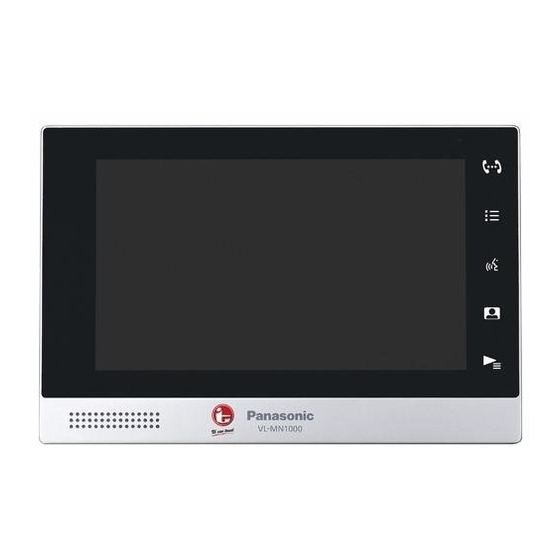
3. Preparation This button flashes on the "main" room monitor when 3.1 Device diagrams there are new text messages, voice messages, video messages, or missed calls. It does not flash on a Front view "sub" room monitor. 3. . Preparation Terminal connector Used to connect external devices (user supplied) to the room monitor. -
Page 9: Home Screen
3. Preparation “Alarm” and “Message” feature buttons: Tap the 3.2 Home screen corresponding feature button. Once you have tapped each new item in the alarm log or message You can display the home screen by tapping the display list, the number icon disappears. when the display is turned off, and by tapping when the display is on. -
Page 10: Feature Screens
3. Preparation 3.3 Feature screens 3.4 Status icons Tapping a feature button in the home screen displays the Status bar icons corresponding feature screen. Indicates the room monitor is connected to Layout and available features vary depending on the the network. screen;... -
Page 11: Main Vs. Sub Room Monitors
3. Preparation 3.5 Main vs. sub room monitors If there are multiple room monitors installed in the residence, one room monitor is the "main" room monitor and the others are "sub" room monitors. This is determined at the time of system configuration and cannot be changed by residents. -
Page 12: Talking And Monitoring Features
4. Talking and monitoring features 4.1 Difference between talking 4.2 Answering calls and monitoring When you receive a call, the room monitor rings. If the 4. . Talking and monitoring features other party is using a device with a camera (such as a "Talking"... -
Page 13: Making Calls
4. Talking and monitoring features Note: 4.3 Making calls R Certain features may not be available depending on system configuration, the type of device being used You can call other residences, common area phones or by the other party, etc. the facility staff office, and even other rooms in your own residence. -
Page 14: Transferring Calls
4. Talking and monitoring features 4.4 Transferring calls 4.5 Monitoring camera images While talking on a call, you can transfer the call to another You can monitor live camera images from lobby stations, room monitor within your residence or to another your own door stations, and other cameras installed in residence. -
Page 15: Viewing Call Log
4. Talking and monitoring features 4.6 Viewing call log The room monitor logs information about calls you have answered, missed, and made, and saves it in the call log. Follow this procedure to view the call log. From the home screen, tap “Talk”. Tap “Call Log”... -
Page 16: Playback And Messaging Features
5. Playback and messaging features 5.1 Playing video messages from 5.2 Playing videos you recorded visitors You can record camera images manually while talking to 5. . Playback and messaging features a visitor or monitoring camera images. Visitors who call you from a lobby station can leave you Follow this procedure to play your videos. -
Page 17: Controlling Video Playback
5. Playback and messaging features 5.3 Controlling video playback 5.4 Viewing pictures The following controls are available by tapping the When a visitor calls you from a lobby station or door screen while playing a video. station, a picture can be captured automatically. You can also capture pictures manually while talking to a visitor Pauses video playback. -
Page 18: Viewing Text Messages From Facility Staff
5. Playback and messaging features 5.5 Viewing text messages from 5.6 Playing voice messages from facility staff facility staff Facility staff can send text messages to room monitors Facility staff can send voice messages to room monitors throughout the facility. If you receive a message from throughout the facility. -
Page 19: Alarm Features
6. Alarm features 6.1 Alarm features overview 6.2 Changing the arm mode Devices and notifications Arming the system 6. . Alarm features Commercially available push buttons and sensors can 1. From the home screen, tap the current arm mode be connected to the room monitor, such as a doorbell, (displayed in the lower-right corner of the display). -
Page 20: Configuring Each Arm Mode
6. Alarm features 6.3 Configuring each arm mode 6.4 Changing alarm feature settings You can select which alarm features are enabled and disabled for each arm mode. From the home screen, tap “Alarm”. From the home screen, tap “Alarm”. Tap “Alarm Status” on the left side of the screen. Tap “Mode Settings”... -
Page 21: Confirming Alarm Feature Status And Settings
6. Alarm features – “Exit Delay”: When you set the arm mode to 6.5 Confirming alarm feature “Out”, the exit delay can give you time to leave the house before the alarm features are enabled. status and settings Available only when “Timing” is set to “Delay Alarm”. -
Page 22: Phonebook Features
7. Phonebook features 7.1 Viewing the phonebook 7.2 Adding entries You can add the rooms you call frequently to the room From the home screen, tap “Talk”. 7. . Phonebook features monitor’s phonebook for easy calling. Tap “Call” on the left side of the screen. Follow this procedure to view your phonebook. -
Page 23: Room Monitor Settings
8. Room monitor settings 8.1 Changing the room monitor’s settings From the home screen, tap “Settings”. 8. . Room monitor settings R A list of available setting categories is displayed. Select “User Settings” on the left side of the screen. R “Administrator”... - Page 24 8. Room monitor settings Category Settings Description Memory — Displays the amount of space used/available in the room monitor’s memory. Format Allows you to delete all content in the room monitor’s memory. The user password is required in order to use this feature.
-
Page 25: Lobby Station Features
9. Lobby station features 9.1 Lobby station overview 9.2 Lobby station operations This section briefly explains how to operate commonly 9. . Lobby station features 9.2.1 Calling a resident used features of the lobby station. Enter the resident’s room number. Press M N to call. -
Page 26: Troubleshooting
10. Troubleshooting 10.1 Troubleshooting Camera images (lobby station and door station images) 10. . Troubleshooting Problem Cause & Solution Page Images appear distorted. R Images may appear distorted because of the characteristics of the – camera lens. This is not a malfunction. The image of the subject R At night or when there is poor light in the area around the lobby station is displayed in black and... -
Page 27: Error Messages
10. Troubleshooting Other Problem Cause & Solution Page The display does not turn R The room monitor is not receiving power. → When using Power over Ethernet (PoE) Make sure the PoE power supply is turned on and supplying power, then check the LAN cable connection. -
Page 28: Other Information
11. Other information Power Supply Unit (VL-PS240, sold separately) 11.1 Specifications The power supply unit is for indoor use only. Room Monitor (VL-MN1000) Power source Input: 220-240 V AC, 0.2 A, 11. . Other information 50/60 Hz Power source When using PoE: Class 2, IEEE Output: 24 V DC, 0.6 A... -
Page 29: Cleaning
This information is available at the following web page: http://panasonic.net/pcc/support/intercom/vn1900 At least three (3) years from delivery of this product, Panasonic Corporation will give to any third party who contacts us at the contact information provided below, for a charge of no more than the cost of physically... -
Page 30: Installation
12.2 Optional items The following items are included in addition to the room The following items are sold separately. Please contact 12. . Installation monitor. your nearest Panasonic dealer for sales information. Compatible accessories (as of March, 2017) Item Quantity Item Model no. -
Page 31: Installation Cautions
12. Installation 12.3 Installation cautions 12.6 Installing the power supply unit (sold separately) Refer to the information found in 2 Important information (Page 4) before installing the product. If the room monitor will not be powered via PoE, you must install a power supply unit. - Page 32 12. Installation wire should be connected to, and insert the DC 12.6.1 Connecting the AC wires, DC wires, wires as shown. and DC plug Strip the ends of the wires that connect to the power CAUTION supply unit as shown below. AC wires DC wires R Insert the power cables firmly all the way into the...
- Page 33 12. Installation Solder the ends of the DC wires to the DC plug. Use 12.6.2 Mounting on a DIN rail insulation sleeves to insulate the wires. Attach the power supply unit to the DIN rail so that the bottom hook is positioned at the bottom of the power supply unit.
-
Page 34: Installing The Room Monitor
12. Installation R To prevent malfunction and sound cutting out, leave 12.7 Installing the room monitor at least 20 cm of space above, below, and on the sides of the room monitor. Required items – Mounting bracket (included) – Screws (included) –... - Page 35 12. Installation Attach the room monitor to the mounting bracket by 12.7.1 Installing by using mounting bracket first lining up the tab on the bottom of the bracket with the groove on the room monitor. Determine the installation location of the room monitor (Installation location (Page 34)).
- Page 36 12. Installation Install the flush mount box in the wall and attach the 12.7.2 Installing by using the flush mount box mounting bracket to the flush mount box using the 3 (sold separately) mounting screws. Open a hole in the wall for the flush mount box. R Note the dimensions of the flush mount box.
-
Page 37: Connecting External Devices
12. Installation 12.7.3 Connecting the wires and cables 12.8 Connecting external devices Connect the LAN cable to the LAN connector. Up to 6 external devices can be connected to the room monitor. External devices are connected to the room Optional monitor by using the 12-pin terminal cable. -
Page 38: Wiring Schematic
12. Installation 12.9 Wiring schematic Door station Room monitor Connection device for option input (A contact) DC-IN 24 V DC 24 V To AC POWER power outlet 24 V DC DC-IN SUPPLY 24 V R2R1 To AC UNIT POWER power outlet SUPPLY UNIT RELAY BOX... -
Page 39: Initial Setup For Room Monitors
12. Installation 12.11 Initial setup for room monitors The first time the room monitor is turned on, it will automatically attempt to download its configuration file over the network from the computer being used for PC programming. Make sure the computer used for PC programming is connected to the network. - Page 40 1006, Oaza Kadoma, Kadoma-shi, Osaka 571-8501, Japan http://www.panasonic.com © Panasonic Corporation 2017 PNQP1323ZA C0317MG0...