Advertisement
Quick Links
T
e
c
T
e
c
T
e
c
E
E
Copyright © 1985~ 2007, E-TEN Information Systems Co., Ltd. All Rights Reserved.
h
n
i
c
a
l
S
h
n
i
c
a
l
S
h
n
i
c
a
l
S
f
o
r
C
f
o
r
C
f
o
r
C
glofiish
August 10, 2007
T
E
N
I
n
f
o
r
m
T
E
N
I
n
f
o
r
m
e
r
v
i
c
e
M
e
r
v
i
c
e
M
e
r
v
i
c
e
u
s
t
o
m
e
u
s
t
o
m
e
u
s
t
o
m
e
®
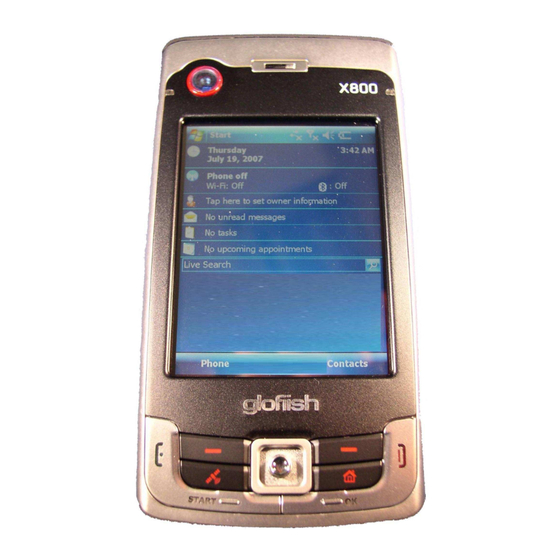
X800
Rev 1.1
a
t
i
o
n
S
y
s
t
e
m
a
t
i
o
n
S
y
s
t
e
m
a
n
u
a
l
a
n
u
a
l
M
a
n
u
a
l
r
r
r
C
o
r
p
.
C
o
r
p
.
1
Advertisement

Summary of Contents for ETen glofiish x800
- Page 1 glofiish ® X800 Rev 1.1 August 10, 2007 Copyright © 1985~ 2007, E-TEN Information Systems Co., Ltd. All Rights Reserved.
- Page 2 TABLE OF CONTENTS CHAPTER 1 I ····································································································· NTRODUCTION CHAPTER 2 P ······················································································ RODUCT PECIFICATION 2.1 P ················································································· RODUCT PECIFICATION 2.2 O ·················································································· VERVIEW OF URFACE CHAPTER 3 T ···························································································· OOLING FOR EPAIR CHAPTER 4 M ·································································································· WITCHING CHAPTER 5 D ········································································································...
- Page 3 CHAPTER 1. INTRODUCTION This manual provides technical information necessary to maintain and support repair ® service of Pocket PC Phone glofiish X800. Information contained in this document is copyrighted by E-TEN Information Systems Co., Ltd. It is intended for use of E-TEN’s authorized service providers and clients.
-
Page 4: Product Specification
CHAPTER 2. PRODUCT SPECIFICATION 2.1 Product Specification Operating System Windows Mobile™ 6.0 for Pocket PC Phone Edition Processor Samsung SC3 2442, 500MHz Memory 64MB RAM, 256MB ROM Display 2.8" VGA, 65,536 colors TFT-LCD touch panel ( Resolution : 640 x 480 ) Dimensions 113.5 (L) x 60.5 (W) x 15.8 (H) mm Weight... - Page 5 Quick Application key x 6 ( Right Softkey / Left Softkey / GPS hotkey / M-desk hotkey / OK / Start ) Battery 1530 mAh Li-Poly, rechargeable & replaceable Power DC Adaptor, 5V1A, LED Indication << Right-Up side: Red, Green >> - Red always light: Device is charging - Red sparkling once every 4 sec: Warning of Battery low level - Red sparkling twice repeatedly: Warning of Battery critical situation.
- Page 6 2.2 Overview ○ ○ ○ Volume Adjustment Left Soft-Key Power key ○ ○ ○ Recorder key Right Soft-Key Camera shoot key ○ ○ ○ Reset key M-Desk 2M AF Camera Lens ○ ○ ○ Headset Jack Send / Hang on Contact list Mirror ○...
- Page 7 CHAPTER 3. TOOLING FOR REPAIR Item Purpose Cleaning Wipers Disassembly & Assembly T5 Screwdriver Tweezers Plastic Stick Blower Camera Lens Clean Soft Brush Mini USB Cable / Cradle Synchronization Test to PC Micro SD Card SD Read / Write Test Headset Headset Audio / Recording / FM Test AC Adapter...
- Page 8 CHAPTER 4. MODE SWITCHING Function Procedure Hardware Reset 1. Press and hold POWER button 2. Press RESET button and release both (power & reset) buttons at the same time Software Reset Press RESET button Testing (Build-in) Program 1. Press and hold CAMERA button immediately after doing a hardware reset 2.
- Page 9 CHAPTER 5. DIAGNOSTICS 5.1 PDA Build-in Diagnostic Program How to entering the program: a. Press and hold POWER button b. Press RESET button and release both buttons at the same time c. Press and hold CAMERA button immediately after having hardware reset (above 1 & 2) d.
- Page 10 T Panel Touch Panel test Take stylus pen then draw few lines slowly around the screen rims and center. *Breaking lines and screen can’t alignment are not allowed. Tap up-right corner to exit AUDIO Voice record/reply test 1. Tap Recording icon and talk to the microphone for 1-2 sec, the voice will reply the recorded sound automatically.
- Page 11 5.2 Other Function Test Under OS Testing Item Procedures Guidelines Phone Live Test dial and receive phone calls Check Dial/Receive phone call’s voice is Test 1. Using Device over device to test clear enough 2. Using Headset to answer a call 3.
- Page 12 CHAPTER 6. DISASSEMBLY *Quick Ref. Figure Reading Sequences P/N: 49005120 Battery Cover & Stylus & Battery, SIM Card( ( ( ( if has) ) ) ) Main Unit 40009520 40009510 A. Remove battery-cover from the unit, bottom side go first. B.
- Page 13 Main Bracket Assy Antenna Cover Assy P/N: 64041640 A. Use plastic-stick to insert the latch hole, dig it up with a little strength. B. When finished, taking care of the other side as well. Unlock all latches and remove Cover from the bracket.
- Page 14 Front Cover Assy( ( ( ( unscrew needed) ) ) ) Main Bracket Assy P/N: 44001160*2 Copyright © 1985~ 2007, E-TEN Information Systems Co., Ltd. All Rights Reserved.
- Page 15 A. Two screw holes are at bottom of the unit. Use T5-screwdriver to unscrew them both. B. Use plastic-stick to pick a hole near the camera-button, dig it up by using a little strength. C. Sliding stick to the top of cover, separate them from the bracket. D.
- Page 16 A. Use plastic-stick to digging gap with a little strength, nicely to pick the Keypad Module up. B. Bending FPC to the opposite way. Unlock connector from socket by using tweezers. C. Finish. Caution!! Use tweezers in an ease way to get the helps. The FPC Assy or other parts could be damaged by tools misusage.
- Page 17 A. Two screw holes at top of the unit. Use T5-screwdriver to unscrew them both. B. Use plastic-stick digging M/B a little out from the top corner of bracket. C. Hold the unit and make it straight on the desk. D.
- Page 18 A. Pulling out Speaker from bracket with the hook side of plastic-stick. B. Pick Vibrator out from bracket by using tweezers. C. Pick key rubber up from the bracket. Note. Removing the tape as clean as possible and make it ready for the new parts on the bracket. P/N: 64041620 43001060 Rubber MIC &...
- Page 19 P/N: 02000670 LCM & Shielding LCM 41002650 A. Unlock LCM connector on the M/B. B. Release all shielding latches along the edge of M/B. C. Pick M/B up from LCM shielding, handle with care if you were caught it by hands. D.
- Page 20 CHAPTER 7. ASSEMBLY *Quick Ref. Figure Reading Sequences P/N: 02000670 41002650 LCM & Shielding LCM 64041620 Copyright © 1985~ 2007, E-TEN Information Systems Co., Ltd. All Rights Reserved.
- Page 21 A. Place LCM module and fit its edge of the shielding with carefully. B. Put M/B onto LCM, lean it close to the side of FPC connector first. C. Use tweezers to make sure all latch locked. D. Bending FPC connector slightly down right into the socket on M/B, lock up the latch. E.
- Page 22 A. Placing the CAM, aim connector to the socket on top of M/B. B. Hand shielding over the CAM, put it down to lock the frame-socket well on M/B. Check it has mount well around the shielding. C. Finish. Caution!! The CAM module can be placed by the wrong direction as well. P/N: 43001070 49005260 Rubber Reset Key &...
- Page 23 Main Bracket Assy( ( ( ( screw needed) ) ) ) P/N: 44001160*2 Copyright © 1985~ 2007, E-TEN Information Systems Co., Ltd. All Rights Reserved.
- Page 24 A. Handling bottom side of M/B with a bevel angle into the main bracket. B. Sliding headset-jack right into the case the first. C. When headset has stuck, aim mini USB to lock its port, you will hear a “CLICK” sound if the action is correct.
- Page 25 Main Bracket Assy( ( ( ( screw needed) ) ) ) Front Cover Assy P/N: 44001160*2 Copyright © 1985~ 2007, E-TEN Information Systems Co., Ltd. All Rights Reserved.
- Page 26 A. Leaning the top of Cover to lock the latch on main bracket. B. Use fingers to pressing the top, bend it down slowly. C. Sliding your finger along the edge side to get close enough on bracket. D. Lock keypad module FPC connector by using tweezers, stretching inside with carefully. E.
- Page 27 A. Leaning the top of Cover to lock the latch on main bracket. Slide your finger down to its bottom case. B. Make sure both sides are fitting well to the case. C. Take care center part of the bottom, push it down to latch hole. D.
- Page 28 CHAPTER 8. SPARE PARTS LIST 8.1 Spare Parts For Repair E-TEN P/N Description Usage Q'ty Picture 02000670 LCM, X800 03040220 Camera 2M, X800 33001670 Gasket LCM, X800 33001680 Gasket LCM-Short, X800 33001710 Gasket FPC, X800 40009410 Main Bracket Assy, X800 Copyright ©...
- Page 29 40009510 Battery Cover, X800 40010600 Keypad Module Assy, X800 41002650 Shielding LCM, X800 41002670 Shielding Camera, X800 43001060 Rubber MIC, X800 43001070 Rubber Reset Key, X800 44001160 Screw, M1.6x4mm, T0.5 Copyright © 1985~ 2007, E-TEN Information Systems Co., Ltd. All Rights Reserved.
- Page 30 46101220 Mylar LCM, X800 49005260 Vibrator, X800 49005270 MIC, X800 49005280 Receiver, X800 49005290 Speaker, X800 53006090 Regulation Label 58000550 Sponge Speaker PCB, X800 Copyright © 1985~ 2007, E-TEN Information Systems Co., Ltd. All Rights Reserved.
- Page 31 58000560 Sponge Speaker Shielding, X800 58000570 Sponge SD Door, X800 58000780 Sponge Stylus, X800 64041620 M/B, X800 64041640 Antenna Cover Assy, X800 64041650 Front Cover Assy, X800 Copyright © 1985~ 2007, E-TEN Information Systems Co., Ltd. All Rights Reserved.
- Page 32 8.2 Accessory List Item 31301040 USB Cable 40009520 Stylus, X800 40009570 Stylus with bag packing, X800 47000430 Leather Pouch, X800 49004450 Headset 49005040 AC Adapter, X800 49005120 Li-poly Battery, X800 49003940 AC Adapter US-Plug 49004260 AC Adapter AU-Plug 49090020 AC Adapter EU-Plug 49090030 AC Adapter UK-Plug Copyright ©...
-
Page 33: System Requirements
CHAPTER 9. SOFTWARE UPGRADE 9.1 System Requirements: Microsoft® Windows 2000, XP or above Latest version of EUU (End User Upgrade) or Bin file utilities for X800(EUU_xxx.exe) Latest version of ActiveSync v4.5 or above Tool: mini USB Cable Note: E-ten releases both EUU and Bin file for an authorized Service Center. Distributors and local service agent shall only receive EUU software. - Page 34 CHAPTER 10. DEFINITION OF SERIAL NUMBER MFYMDDB##### Handset Label Serial Number consists of 12 digital as following format: ##### Model Code Handset Serial Number Year Month X800 Band Q’ty Ex: 03214 Manufacture Data 1= 2001 2= 2002 3= 2003 4= 2004 5= 2005 6= 2006 Year 7= 2007 8= 2008 9= 2009 A= 2010 B= 2011 C= 2012 1= Jan 2= Feb...
- Page 35 CHAPTER 11. INSPECTION CRITERIA (LCM) Defective Pixel on LCM Service technicians must test by the LCD color test in the build-in diagnostic program. The maximum of allowable defective dot is Three (3) for criteria 1 and 2. Criteria 1 : If service technicians see more than 3 bright dots under the black screen, it means changing LCM is required Criteria 2 : If service technicians see more than 3 black dots under the bright screen, it means changing LCM is required...
- Page 36 ANNEX. REVISION HISTORY Date Version Update August 1, 2007 First Edition August 10, 2007 a. Ch6/Ch7 Quick Ref. added b. Ch8/Ch10 items updated c. RF Antenna Test Criteria removed Copyright © 1985~ 2007, E-TEN Information Systems Co., Ltd. All Rights Reserved.
Need help?
Do you have a question about the glofiish x800 and is the answer not in the manual?
Questions and answers