Table of Contents
Advertisement
Quick Links
Download this manual
See also:
Operating Manual
Advertisement
Table of Contents

Related Manuals for Gtech EB01

Summary of Contents for Gtech EB01
- Page 1 EB01 and EB02 OPERATING MANUAL...
-
Page 2: Personal Safety
The term “eBike” throughout this manual refers to your Electrically Power Assisted Cycle. • You can fit a Gtech approved luggage carrier to Personal Safety: your eBike. Please check with the manufacturer • This eBike is intended for use as a commuter to make sure that a child seat can be safely and trekking bicycle. - Page 3 • Do not abuse the charger cord. Never carry the • Do not lubricate the belt drive. charger by the cord. • Keep body parts and clothing away from the • Do not pull the cord to disconnect from a belt drive when in motion, otherwise they might socket;...
-
Page 4: Warranty Registration
Thank you for choosing a Gtech eBike “I started Gtech to create sensible, easy to use products, which do a great job. Your opinion is important to us. Please take the time to write a review of the eBike by emailing us at support@gtech.co.uk. - Page 5 Frame choice The Gtech eBike comes in two different frame sizes, designed to fit a wide range of people. The Sport is a cross-bar model and the City is a step-through with a comfort seat. Apart from those differences the bikes are similar.
- Page 6 Assembly What’s in the box: Sport Your Gtech eBike comes partially assembled. You will, however, need to complete the assembly. By following these instructions you should be able to do this with minimal fuss. Please pay particular attention to the safety messages.
- Page 7 Assembly What’s in the box: City Your Gtech eBike comes partially assembled. You will, however, need to complete the assembly. By following these instructions you should be able to do this with minimal fuss. Please pay particular attention to the safety messages.
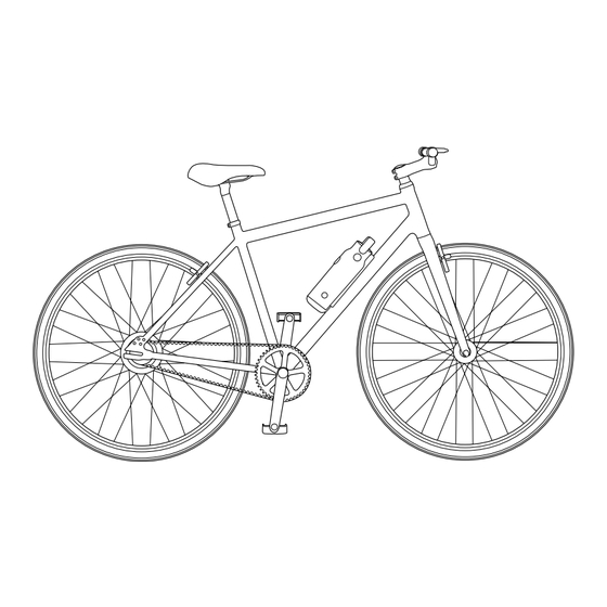
- Page 8 Assembly eBike Sport: parts Saddle Seat Post Saddle Quick-release Rear Brakes Dropout Plate Rear Dropout Motor Rear Sprocket Drive Belt Pedal Sprocket Crank Pedal...
- Page 9 Assembly Battery Handlebar Stem Handlebars Head Tube Front Brakes Front Forks Front Dropout Battery Cradle...
- Page 10 Assembly eBike City: parts Saddle Seat Post Saddle Quick-release Seat Tube Rear Brakes Seat Stay Dropout Motor Rear Sprocket Chain Stay Drive Belt Pedal Sprocket Crank Pedal...
- Page 11 Assembly Battery Handlebar Stem Handlebars Head Tube Front Brakes Front Forks Front Dropout Down Tube Battery Cradle...
-
Page 12: Table Of Contents
Assembling the kickstand ............31 Assembling the mudguards ............33 Finding the correct saddle height ..........37 Adjusting the saddle height ............38 Adjusting the saddle angle and travel ...........39 Storing the Gtech tool ..............40 Attaching the battery ..............41 Removing the battery ..............42 Operation Operation ..................43 Charging the battery ..............44... - Page 13 Maintenance Maintenance ................48 Inflating the tyres .................49 Removing the front wheel ............51 Removing the rear wheel .............52 Replacing the inner tube ..............55 Handling the drive belt ..............58 Attaching the rear wheel ..............61 Adjusting the brake cable ............65 Replacing the brake pads ............67 Technical Specification Technical Specification ..............69 Tightening Torques ..............69...
-
Page 14: Assembly
Finding the correct saddle height ..........37 Adjusting the saddle height ............38 Adjusting the saddle angle and travel ...........39 Storing the Gtech tool ..............40 Attaching the battery ..............41 Removing the battery ..............42 Make sure that you follow all of the instructions in this manual carefully to assemble your eBike cor- rectly before use. -
Page 15: Assembly
Attaching the handlebars Attaching the handlebars Place the eBike frame upright on a flat surface, you Using the Gtech tool, carefully unscrew the may need to put something down on the surface handlebar plate from the handlebar stem by to stop your bike frame from getting scratched. - Page 16 Note: The handlebar plate can go either way up. top and the bottom of the handlebar. Carefully insert the four screws (with washers) Using the Gtech tool, tighten all of the screws making sure the threads are engaged well. evenly by turning them clockwise. Tighten Screw in by hand, starting with two that are in small increments in a criss-cross pattern.
- Page 17 Assembly IMPORTANT: After fitting the handlebar check carefully before your first ride. Loose or incorrect fitting of the handlebar can lead to loss of control and the risk of serious injury. Should you have any concerns regarding the assembly of the handlebar we recommend your Ebike is checked by an experienced mechanic or a professional bike shop.
-
Page 18: Attaching The Saddle
Assembly Attaching the saddle The seat tube has a quick-release fitting on it to make it easier to attach and adjust the saddle’s height. To operate the quick-release, follow these instructions: Refer to page 38 for adjusting the saddle to the recommended height and position. 1. -
Page 19: How To Fit The Front Wheel
Assembly How to fit the front wheel Make sure that the 2 black plastic wheel protectors have been removed from the wheel. Be careful when removing these, so they do not snap off and become stuck in the wheel. Remove the front fork spacer. - Page 20 Assembly Fit the spring onto the quick release shaft, with Screw the adjustment nut onto the end of the the narrow end facing towards the wheel. quick-release, next to the spring, by turning it clockwise. Only 2 to 3 turns are required, leaving a gap to slot the front wheel onto the forks.
- Page 21 Assembly If the lever is too easy to close return it to the Push the quick-release lever fully closed. open position and tighten the adjustment nut a You should need to use the palm of your hand to close the quick release lever with as much quarter turn clockwise.
-
Page 22: Fitting The Pedals
Assembly Fitting the pedals Match the pedal marked L with the crank marked Match the pedal marked R with the crank marked L, located on the opposite side to the drive belt. R, located on the opposite side to the drive belt. Carefully align the pedal into the crank hole. -
Page 23: Assembling The Front Brakes
Assembly Assembling the front brake Stand your eBike in an upright position. The front brake arms and brake cable are located Squeeze the brake arms together. at the top of the wheel, in front of the forks. Pull the silver cable guide and then insert the end Release the brake arms. - Page 24 Assembly Check the brake cable is located in 3 positions: Push the black rubber cable cover across, so 1. Into the cable guide that it is flush against the cable holder. 2. The cable guide is slotted into the cable holder 3.
-
Page 25: Adjusting The Brake Cable
When each of the brake levers are pulled the surface of both brake pads on either side of the wheel should push onto the wheel rim at the same time. Using the Gtech tool, loosen the cable clamp Unscrew the brake lever mount adjuster barrel... - Page 26 Assembly Screw the brake lever mount adjuster barrel and Pull the brake lever and check that the pads locking ring fully into the lever. Tighten the locking press onto the wheel. When applied the brake ring against the brake lever mount. lever should move about half the distance to the handle bar grip.
-
Page 27: Aligning The Brake Pads
Assembly Aligning the brake pads The brake pads should be aligned accurately against the wheel rim. Check both the left and right brake pads are correctly aligned, on both the front and rear brakes. Squeezing the brakes showing alignment of brakes Squeeze the brake arm so the pad touches the To adjust the brake pad loosen the brake pad wheel rim and check it touches the centre of the... -
Page 28: Adjusting Brake Travel
Assembly Adjusting brake travel Your brake pads should hit both sides of the wheel rim at the same time. If this doesn’t happen you will need to adjust them. If the brake arms are mis-aligned from a centre position so one side touches the wheel rim before the other then follow these steps. - Page 29 Assembly IMPORTANT: Before riding your bike check the brake cables are secure, the brakes are correctly adjusted, and operate. Incorrect fitting or alignment of the brakes can lead to the risk of serious injury. Should you have any concerns or uncertainty we recommend your bike is checked by a professional bike shop.
-
Page 30: Attaching The Reflectors
Assembly Attaching the reflectors The clear reflector faces to the front of the eBike and is fitted to the handlebar. Use a Philips head screwdriver to turn the screw Clip the reflector to the handlebar. Locate the anti-clockwise to remove. Retain the nut. nut and insert the screw and turn clockwise to secure the reflector in place Removing screw from rear reflector... -
Page 31: Assembling The Kickstand
Assembly Assembling the kickstand The kickstand is an optional accessory available through www.gtech.co.uk Unscrew and remove the screw and washer from The hole for fixing the kickstand is in front of the the kickstand. Keep them safe. rear wheel. Position the kickstand below the frame. Check Fit the screw with washer through the hole. - Page 32 Assembly Securely tighten the screw using the 8mm allen The kickstand should now touch the floor when key provided. in use. Note: If mudguards are also being fitted the kickstand screw is used to fix the rear mudguard. See page 35. IMPORTANT: Do not sit on the bike with all your weight supported by the kickstand.
-
Page 33: Assembling The Mudguards
Assembly Assembling the mudguards The mudguards are an optional accessory available through www.gtech.co.uk Front mudguard (shorter length mudguard) Insert a round head screw through the hole in the Place the mudguard stay over the screw. front mudguard. Note that the front mudguard stay is slightly longer than the rear. - Page 34 Assembly Insert a fixing screw and tighten using the Gtech Position the stays against the fixing holes at the tool provided. bottom of each side of the front forks. Insert a fixing screw at each side and tighten clockwise using the Gtech tool provided.
- Page 35 Assembly Rear mudguard (longer length mudguard) Insert a round head screw with washer through Place the mudguard stay over the screw. Fit a the hole in the rear mudguard. washer and nut by turning clockwise. Hold the nut to stop it rotating with the 8mm spanner and tighten the screw clockwise using the 3mm allen key provided.
- Page 36 Position the stays against the fixing holes at the frame. Insert a fixing screw and tighten clockwise bottom of the chainstays. Insert a fixing screw at using the Gtech tool provided. each side and tighten clockwise using the Gtech tool provided.
-
Page 37: Finding The Correct Saddle Height
Assembly Finding the correct saddle height Sit on the bike saddle. Try to reach the pedal with your heel when it is in the bottom position. Your knee should be more or less fully straight. Place the balls of your feet on the centre of the If you need to adjust the saddle height pedal. -
Page 38: Adjusting The Saddle Height
Assembly Adjusting the saddle height Pull back the quick-release lever. Adjust the saddle to the correct height for you, making sure that the stop mark is not above the saddle tube. See page 37 for advice about finding the correct saddle height. Close the quick-release by firmly pushing on the Check that the saddle cannot move once the quick-release lever, so that it lies flat against... -
Page 39: Adjusting The Saddle Angle And Travel
Assembly Adjusting the saddle angle and travel 1. The screw for adjusting the saddle is located Now that the saddle is loose you can move it beneath the saddle. horizontally forwards or backwards to improve 2. Whilst looking up at the base of the saddle, your reach to the handlebars. -
Page 40: Storing The Gtech Tool
Assembly Storing the Gtech tool The slot for storing the Gtech tool is located in Line up the notches in the Gtech tool with the the centre of the battery cradle. tabs on the battery cradle. Push the tool down firmly, so that it clicks into place. -
Page 41: Attaching The Battery
Assembly Attaching the battery Sit the battery in the base of the battery cradle, Push the battery firmly down towards the frame. located on the down tube. Make sure that the It will click when it is in place. green power button is facing outwards, away from the down tube. -
Page 42: Removing The Battery
Assembly Removing the battery If you have locked your battery in place, you must unlock it before trying to remove it from the battery cradle: Insert the battery key into the lock and turn To unlock the battery, first remove the rubber anti-clockwise to unlock the battery. -
Page 43: Operation
Assembly Operation Operation ..................43 Charging the battery ..............44 Turning your eBike on ..............45 Brake controls ................47 Ready for your first journey? Before you go out adventuring check that the following steps have been completed in accordance with the instructions in the assembly section. We want to ensure you get the most out of your new eBike and by following the list below you will be ready to get out there with confidence. -
Page 44: Charging The Battery
Operation Charging the battery 1. You can charge the battery while it is still When the lights rapidly cycle red, recharge the battery. attached to your eBike. 2. Plug the charger into a mains power socket, then remove the rubber charging point cover and connect the charger to the battery. -
Page 45: Turning On Your Ebike
Operation Turning your eBike on Your battery has two power settings – High Power & Low Power. The LEDs show how much charge is in the bat- Press the green power button on your battery. tery. Your battery will remember the power mode it was last in. - Page 46 Operation You can still check how much charge is left in To turn the battery off, press and the hold the your battery when it is not attached to the bike. green power button for two seconds. Briefly press the green power button to display the level of charge.
-
Page 47: Brake Controls
Operation Brake Controls The left brake lever activates The right brake lever activates your rear brakes. your front brakes. Always use both brakes together. Emergency braking When emergency braking, your weight will shift forwards, reducing the load on your rear wheel. This can cause your rear wheel to slip, which is dangerous, especially when riding downhill. -
Page 48: Maintenance
Maintenance Maintenance Maintenance ................48 Inflating the tyres .................49 Removing the front wheel ............51 Removing the rear wheel .............52 Replacing the inner tube ..............55 Handling the drive belt ..............58 Attaching the rear wheel ..............61 Adjusting the brake cable ............65 Replacing the brake pads ............67 In this section you will find a break down of adjustments and replaceable parts. -
Page 49: Inflating The Tyres
Inflating the tyres Before starting to inflate your tyres, check that the pump is in the correct mode for your tyre valve. For the Gtech eBike, it will need to be in Schrader mode. Remove the valve cap. Briefly press down on the valve to make sure the valve doesn’t stick and to remove any loose dirt. - Page 50 – printed on the sidewall of the tyre. Remove pump nozzle from the valve stem. Replace the dust cap. The correct pressure for the tyres on the Gtech eBike is: min 50psi, max 75psi. Do not over or under inflate the tyres.
-
Page 51: Removing The Front Wheel
Maintenance Removing the front wheel Detach your brakes, which are located at the Place the frame upside down on a flat surface, top of the front forks, from the front wheel rim resting on the saddle and the handlebars. by closing the brake arms using your thumb and You may need to put something down on the index finger and lifting out the brake cable. -
Page 52: Removing The Rear Wheel
Maintenance Removing the rear wheel Detach your brakes, which are located at the top Adjust the saddle so that it is at its lowest of the rear forks, from the wheel rim by closing position. Turn the bike upside down and place the brake arms using your thumb and index on a soft surface. - Page 53 Maintenance Locate both of the belt tension adjusters at the Loosen the bolts on either side of the wheel by rear forks and, using the tool provided, turn them placing the tool through them and turning anti-clockwise to loosen. Make sure you hold anti-clockwise.
- Page 54 Maintenance Take the drive belt off the rear wheel sprocket and The drive belt needs to stay resting in this move around the rear forks, away from the frame. position. Slide the wheel backwards off the frame to remove.
-
Page 55: Replacing The Inner Tube
Replacing the inner tube You will need a 700C x 35/43c inner tube. These can be ordered at www.gtech.co.uk or can be purchased from good bike shops. If changing the tyre at the same time, you will need a 700 x 38C tyre. - Page 56 Maintenance Run the tyre lever all the way around the tyre. 1. Push the inner tube valve in, towards the tyre. 2. Remove the inner tube from between the outer tyre and rim. To replace... Check the inside of the outer tyre for sharp objects Partially inflate the inner tube.
- Page 57 Refit the wheel onto the bike (see page 32). tyre. The correct pressure for the tyres on the Gtech eBike is: min 50psi, max 75psi. Do not over or under inflate the tyres.
-
Page 58: Handling The Drive Belt
Maintenance Handling the drive belt: At any time when you need to handle the drive belt follow these safeguards: Make sure you read the safety instructions for the drive belt under Important Safeguards (see pages 2-3) before you handle the belt. - Page 59 Maintenance Remove the rear wheel (see page 52). Undo the four nuts on the dropout plate (on the same side as the pedal sprocket) by using the tool provided to turn them anti-clockwise. The nuts are in two parts, ensure you keep both Be careful when removing the last bolt, as the parts safe.
- Page 60 Maintenance Take the belt off the pedal sprocket. Feed the belt through the gap towards you to remove the belt. Feed the new belt through the gap in the 1. Rest the drive belt over the pedal sprocket dropout. next to the frame. 2.
-
Page 61: Attaching The Rear Wheel
Maintenance Attaching the rear wheel Place the frame upside down on a flat surface, Place the dropout plate back onto the bike resting on the saddle and the handlebars. You and align with the holes. Insert all four nuts and may need to put something down on the surface tighten them securely. - Page 62 Maintenance Replace the drive belt onto the rear wheel Slide the wheel back into place, keeping it sprocket, making sure that the teeth pushed forwards on the rear fork, this will are lined up. reduce the distance between the sprockets, helping you to attach the drive belt.
- Page 63 Maintenance Keep the rear wheel in this position and tighten To align the rear wheel with the frame, tighten the the belt tension adjuster screw that is on the other belt tension adjuster screw, located on the same side as the drive belt and sprockets. opposite side.
- Page 64 Maintenance With your eBike upside down, tighten the nuts If the tension is not correct, turn your eBike on either side of the wheel by placing the tool upside down and adjust the belt tension adjuster through them and turning clockwise. screws.
-
Page 65: Adjusting The Brake Cable
Maintenance Adjusting the brake cable You should not be able to pull the brake levers all the way back to the handlebar grip. Over time the brakes will wear down and you will need to tighten the brake cable. Minor adjustments can be made at the brake levers to tighten the brakes. - Page 66 Maintenance If necessary further adjustment can be made at the brake arms. Using the Gtech tool provided, loosen the cable To tighten the brake cable, pull the brake cable clamp screw until the brake cable is free to move through the clamp a little. If you need to loosen through the clamp.
-
Page 67: Replacing The Brake Pads
Maintenance Replacing the brake pads You can judge the wear of your brake pads by the appearance of the grooves. If the pads are worn down to the bottom of the grooves, you will need to replace them immediately with a new set of linear pull brake pads. - Page 68 Maintenance Close the brake arms together using your thumb Hold the brake pad so that its whole surface rests and index finger and put the brake cable guide against the wheel rim and re-tighten the screws. back in place. It is absolutely essential to remember to adjust the brakes after replacing the pads. See page 25.
-
Page 69: Technical Specification
Maintenance EBIKE TECHNICAL SPECIFICATION Sport City eBike model EB01 EB02 1016A0010 1016A0010 Battery model 36V 5.6Ah Li-Ion 36V 5.6Ah Li-Ion Battery 3 hours 3 hours Charging period Battery charger output 42V DC 2.0A 42V DC 2.0A Weight 16kg 16kg Frame 20”... -
Page 70: Warranty
Warranty – Terms and Conditions Your 2-year warranty will be automatically registered for you. If your Gtech eBike breaks, don’t worry, we’re here to help. Go to www.gtech.co.uk or call 01905 345 891 for assistance. WHAT ISN’T COVERED SUMMARY Gtech does not guarantee the repair or •... - Page 72 Grey Technology Limited Brindley Road, Warndon, Worcester WR4 9FB email: support@gtech.co.uk telephone: 01905 345891 www.gtech.co.uk CPN1192...
Need help?
Do you have a question about the EB01 and is the answer not in the manual?
Questions and answers