Table of Contents
Advertisement
Quick Links
Advertisement
Table of Contents

Related Manuals for Quantum RDX 8000


Summary of Contents for Quantum RDX 8000
- Page 1 8000 ® Removable Hard Disk Storage System User Guide PN 6-67387-02 Rev A...
- Page 2 Quantum makes no representation or warranties with respect to the contents of this document and specifically disclaims any implied warranties of merchantability or fitness for any particular purpose. Further, Quantum reserves the right to revise this publication without obligation of Quantum to notify any person or organization of such revision or changes.
-
Page 3: Introduction
For more information go to www.quantum.com/serviceand- support. This warranty does not apply to normal wear or damage from misuse, abuse or accident. Quantum will not be liable for any lost data or other indirect, incidental or consequential damages. This warranty gives you specific rights –... -
Page 4: Table Of Contents
1.4.2 Mode 2 — RDX 8000 JBOD (default setting): ....... . - Page 5 5.11.1 Device - Set Operating Mode ............42 5.11.2 Setting the RDX 8000 Wake up/Sleep mode – CONFIGURE/Device/Power Save Timer ... 45 5.11.3 Cartridge - Labeling tape format cartridges .
-
Page 6: Product Description
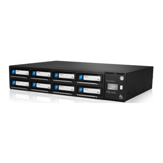
1.1 Overview and applications The RDX 8000 is a multi-cartridge data storage device designed to support up to 8 RDX cartridges. It may be utilized as a table top unit or rack mounted in a 2U high space with the included rack mounting ears. The RDX 8000 connects to the user’s computer network via one 1 GB/sec network port using iSCSI protocol. -
Page 7: Mode 1 - Rdx 8000 Tape Library
RDX cartridge. RDX cartridges which are recorded in this mode are not write/read interchangeable with standard RDX docks. Use of this mode requires the user to pre-format the standard RDX media to the tape format mode. The RDX 8000 unit identifies the current cartridge format via the OCP and RDX 8000 interfaces. -
Page 8: Front Panel
2. Front panel The front panel of the RDX 8000 is constructed of durable plastic and is designed to provide both visual appeal and protection from entry of dust/dirt. The eight spring-loaded cartridge bay doors prevent entry of dust when no cartridge is inserted, protect the unit from ESD, and control the cooling airflow through the device. -
Page 9: Led Behavior
2.2 LED Behavior 2.2.1 Power button LED State Status Description No power No AC Power is present at the RDX 8000 rear connector. Blinking green Unit starting Unit is in the process of becoming ready for operation. Steady green Power on Unit is ready for operation. -
Page 10: Rear Panel
3. Rear panel The rear panel of the RDX 8000 provides access to the power connector, Ethernet ports, power supply and cooling fan. 3.1 Rear panel layout Figure 2 — Rear panel Number Description IEC Power connector -- AC Power connection... -
Page 11: Ethernet Port Led Behavior
Off – indicates no link is established Speed LED: Amber on – indicates a Gigabit connection (1000 Mbps). Green on – indicates a 100-Mbps connection. Off – indicates a 10-Mbps connection. Table 3 — Ethernet port RDX 8000 User Guide... -
Page 12: Product Installation
50-60 Hz line frequency 1.2-0.6 A Locate the RDX 8000 within 6 ft. of an AC outlet. The AC power cord is the RDX 8000 main AC disconnect device and must be easily accessible at all times. Air quality Place the RDX 8000 in an area with minimal sources of particulate generation. -
Page 13: Installation Precautions
4.1.3 Unpacking the unit Before unpacking the unit, clear a work surface to unpack the RDX 8000. Select either a table top location or if the unit is to be rack mounted an open rack location at least 2U spaces in vertical height. - Page 14 • Power cord (region dependent) • Printed Quick Start Guide • RDX cartridges Confirm that you received the following in the RDX 8000 box: • RDX 8000 unit • Rack mounting ears with included mounting hardware • Torx driver for installing rack mounting ears Required additional equipment for a successful installation: • Ethernet cable...
-
Page 15: Installing In A Rack
Required tools: • #3 Phillips screwdriver Rack mounting the RDX 8000: 1. Determine the location in the rack for the unit to be installed. 2. Use a pencil to mark the location on each vertical rail in the rack. -
Page 16: Installing Cables And Connections
The connection to the Ethernet network is via an industry stand RJ45 copper interface on the rear panel of the unit; see section Rear panel. 1. Insert the Ethernet cable into the Ethernet port #1 of the unit. When the plug is in the full seated position, a positive click should be heard. RDX 8000 User Guide... -
Page 17: Powering Up And Powering Down The Unit
The RDX 8000 OCP (Operator Control Panel) will also become active and will display the RDX 8000 unit’s IP address for port 1. Please take note of this IP address which will be used to access the RDX 8000 and for the iSCSI communication. -
Page 18: Product Configuration
5.3 OCP – Operator Control Panel The RDX 8000 unit includes an LCD based display located on the right side of the unit’s front bezel – referred to as the Operator Control Panel or OCP. Highlights of the OCP are: • 64 dot high by 128 dot width graphics display with color backlight... -
Page 19: Ocp Display Content
5.3.1 OCP Display Content Once the RDX 8000 unit completes the power up boot sequence the OCP will become active. The OCP will display the system information screen which identifies the unit’s iSCSI QN name, current IP address / status of Ethernet port 1, as well as the unit current firmware revision level. -
Page 20: Ocp Icons
The RDX 8000 makes use of graphic icons to indicate some conditions to the user. These icons are used both on the local OCP display and in the Active System Graphic in the RDX 8000. The RDX 8000 icons in use are shown in the table below. -
Page 21: Iscsi Connection
JBOD mode: The RDX 8000 will present each of the eight slots as a separate iSCSI target, The target iqn’s will have the format of unit iqn with a ”-x” appended at the end, where “x” is the slot number Tape Library Mode: The RDX 8000 will present itself as a single iSCSI target. - Page 22 4. The IQN(s) for the RDX 8000 unit should be shown under available targets. 5. Highlight the RDX 8000 IQN by clicking on it. 6. Depending upon which version of MS Initiator in use you may need to either click “Log On” or “Connect”.
-
Page 23: Cartridge Ejection
5.5 Cartridge Ejection The RDX 8000 is configured to ensure the integrity of the data written to the cartridges. For that reason, the cartridges are put into the Ejection Protection mode when an iSCSI connection is completed. This mode prevents the user from ejecting the cartridges using the front panel eject buttons or the Eject function in the RDX 8000. -
Page 24: Introduction To The Rdx 8000
5.6 Introduction to the RDX 8000 The RDX 8000 unit uses the Web based RDX 8000 to allow the user to configure and monitor the unit. The RDX 8000 IP address may be viewed in the OCP and is displayed between the cartridge monitoring pages for slot 8 and slot 1 (#1 out of 9 screens in continuous rotation). -
Page 25: Login Procedures
5.7 Login Procedures Access the RDX 8000 remote management interface via a Web browser. Using the IP address visible on the unit’s front panel OCP, enter the IP address into your browser address bar and navigate to the RDX 8000 Login page. - Page 26 “Table 6 — Default User Accounts” on page Secure SSL encryption: The RDX 8000 unit supports a secure connection option to the host system. The SSL certificate is unsigned resulting in a security warning when activating the SSL connection. Table 5 — RDX 8000 Login Detail...
-
Page 27: Ssl Encryption Page
• The RDX 8000 grants access or ability to perform operations based upon user rights. • The RDX 8000 grants the Administrator and Service levels full access to device set up, diagnostics, and logging. • The RDX 8000 grants the User level only the ability to monitor device and cartridge status. -
Page 28: Rdx 8000
The main navigation is performed via selection (via mouse click) of the Main Topic Bar (element 1 in the RDX 8000 page chart) and then selection of the associated Sub Topics (element 2). - Page 29 Main topic bar: This field is visible on all pages. The four main RDX 8000 RMI menus are accessed from this set of choices by selecting with a point and click. Operators with User level credentials will not have access to the “MANAGE”, “CONFIGURE”...
-
Page 30: Rdx 8000 System Information Block
System Date & Time: The current system date and time is displayed. System Mode: This field displays the current RDX 8000 system operating mode. IP Address (for Ethernet port 1): The current port IP address is displayed in this field. -
Page 31: Monitoring Cartridge And Device Status - The Monitor Tab
5.9 Monitoring cartridge and device status – The MONITOR tab The RDX 8000 unit user home page is the “MONITOR” tab for all account logins. Following is a brief description of each function. 5.9.1 Cartridge Status page This section depicts the Monitor Cartridge Status page and describes each field on the page. -
Page 32: Cartridge Identity Page
This field shows the storage capacity of the RDX cartridge in GB. Type: This field indicates the format of the cartridge as either tape or disk. Note that using the RDX 8000 in Tape Library mode requires that the cartridges be formatted as tape. -
Page 33: Device Status Page
Name: This field displays the System Name. IP Address: This field displays the IP address for the device. This address is used to provide access both to the RDX 8000 connection and the iSCSI connection. Total Power On Time: This field displays the total power on time since the last system reboot event. - Page 34 This field displays the power supply status -- Power Good or Power Error. The Power Supply Status will be set to Power Error if any of the monitored voltages fall below or exceed normal operating parameters. RDX 8000 User Guide...
-
Page 35: Network Status Page
Link Speed: This field indicates the current network connection speed for the link. To achieve maximum performance the RDX 8000 should to be connected to the network via a 1 GB/s connection. -
Page 36: Device Identity Page
This section depicts the Monitor Device Identity page and describes each field on the page. Figure 18 — RDX 8000 Monitor Device Identity Vendor ID: This field shows the manufacturer of the RDX 8000 device. Product ID: This field shows the product name. -
Page 37: Managing The Unit - The Manage Tab
(unload drive) operator in the center. Also, selecting any other cartridge from the storage slot side and choosing the load button will result in the automatic unload of the cartridge in the drive. The RDX 8000 will only store cartridges back into their original storage slot location (it is not possible to ‘move”... - Page 38 Figure 19 — RDX 8000 Manage Library RDX 8000 User Guide...
-
Page 39: Ejecting Cartridges
5.10.2 Ejecting cartridges Depending on the RDX 8000 System Mode, and current activity, cartridges may be ejected on the MANAGE/Eject Car- tridge screen. The cartridge is ejected by selecting the appropriate slot from the drop down menu and clicking the Eject button. -
Page 40: Initializing Cartridges
5.10.3 Initializing cartridges The RDX 8000 uses a specially format on the RDX cartridges to support emulation of tape. In order to apply this special format the user performs a “pre-format” operation via the Initialize Cartridge function. This cartridge formatting opera- tion is only necessary to perform once and it is suggested the user prepare all cartridges which will be used in the media pool at one time. - Page 41 To convert previously tape formatted RDX cartridges back into standard RDX disk format select the “MANAGE/Initialize Cartridge - Disk” tab and select which cartridge(s) will be formatted back to standard disk format. Conversion of cartridges from tape emulation back to disk format is done using the NTFS format. RDX 8000 User Guide...
-
Page 42: User Operations - The Configure Tab
Administrator or Service. 5.11.1 Device - Set Operating Mode The Device page allows the user to configure the operating mode of the RDX 8000, as well as the System Name and the Global Cartridge Lock status. - Page 43 Figure 23 — RDX 8000 Configure Device - Tape Library Mode To change the RDX 8000 operating mode, select the desired operation mode from the System Mode box. Click the “Submit” button to apply the changes. A confirmation dialog will appear as follows:...
- Page 44 Listed below is a description of the fields and selections on this page. JBOD mode JBOD mode allows the RDX 8000 to appear to the host operating system as 8 individual storage drives -- each with their own drive letter.
-
Page 45: Setting The Rdx 8000 Wake Up/Sleep Mode - Configure/Device/Power Save Timer
5.11.2 Setting the RDX 8000 Wake up/Sleep mode – CONFIGURE/Device/Power Save Timer The RDX 8000 has the ability to schedule auto power on and auto power off events. The user may set both a daily power on time and a daily power off time and choose to enable each one individually. -
Page 46: Cartridge - Labeling Tape Format Cartridges
25 characters long. This custom label will both be displayed in the RDX 8000 and shown as the volume label in the tape backup application. It is strongly recommended that if the user intends to use custom labels they first assign these labels before the RDX media is added to the tape application media set. -
Page 47: Network Settings
1500 and 9000 – 1500 is the default size. Stack: The Stack selects the version of the Internet protocol the RDX 8000 will use when communicating on the network. Current selection option, and default choice, is IPV4. RDX 8000 User Guide... - Page 48 Method: The Method will select the IP addressing mode the RDX 8000 will use. The two options are DHCP or Manual. The RDX 8000 default configuration is DHCP. • DHCP – the RDX 8000 will seek out the DHCP-sever on your network and automatically obtain an IP address from the server each time it powers up.
-
Page 49: Iscsi Settings
Host Name: Enter the name you wish to use to address this RDX 8000. It is recommended that you use a name that is relevant to its location and or its purpose. Domain Name: Enter the name of the domain or workgroup for the attached network. - Page 50 This field allows for the automated discovery, management, and configuration of iSCSI devices from a central point. If this option is enabled the RDX 8000 will register its resources with a central iSNS-server. To enable iSNS on the RDX 8000, click the check box “Enable iSNS” and enter the IP address for the iSNS-Server in the “iSNS Server” field.
- Page 51 “Username” and “Target Secret” to gain access to the RDX 8000. The “Initia- tor Secret” field is provided to allow iSCSI mutual CHAP. If mutual CHAP is selected on the Initiator, the RDX 8000 will authenticate itself with the initiator using the supplied Initiator Secret.
-
Page 52: User Settings
Assign access rights to the account as follows. User level: User level access only allows access to the “MONITOR” functions of the RDX 8000. Administrator level: Administrator level grants access to all functions within the unit including “MONITOR”, “CONFIGURE”, “MANAGE”... -
Page 53: Date And Time Settings
RDX 8000 unit to remote users. There are four tabs related to configuring the time on the RDX 8000 unit. Time Zone: The Time Zone tab allows the user to specifically adjust the time to their local time zone. - Page 54 The time may be set by clicking in the time field and entering the time . Clicking the “Now” button will synchronize the RDX 8000 system time with the time of the computer accessing the RDX 8000. Save the changes to the date and time by clicking the “Submit” button.
- Page 55 Figure 34 — RDX 8000 Configure Date/Time Date/Time Format The Date/Time Format tab allows the user to set the display format of the date and time zone independently. The date setting supports the following formats; English (MM/DD/YYYY) European (DD/MM/YYYY) International (YYYY-MM-DD) The time settings support display of either 12 hour or 24 hour time displayed in the following format;...
- Page 56 Figure 35 — RDX 8000 Configure Date/Time Format RDX 8000 User Guide...
- Page 57 The NTP tab allows the administrator to set a path to a Network Time Server (if an NTP server is configured on their particular network). The RDX 8000 will synchronize with the NTP time server every eight hours. To use the NTP time synchronization, select Enable and enter the name or IP address of the desired time server. Click the Submit button for the settings to take effect.
-
Page 58: Notification Settings
5.11.8 Notification settings E-mail Notification allows the user to configure the RDX 8000 to send e-mail to a selected account upon an identified level of system event. The Notification tab has the following fields: Enable E-mail notification: This check box will enable The E-mail Notification action, and will allow the user to configure the e-mail parameters. - Page 59 Enter the authorized user password for connecting to the selected SMTP server. If you select SUBMIT a test mail will be send. If with your settings the system cannot contact the SMPT Server you will be informed about this in the System Information Field (i). RDX 8000 User Guide...
-
Page 60: Save/Restore Configuration
This tab allows a user to save the current user programmed configuration values/settings. This allows the backup of settings and also supports unit replacement/service. The Configuration file may be stored to a location on the RDX 8000 host computer via selecting the Save Configuration button and downloading the file. - Page 61 Figure 39 — RDX 8000 Restore Configuration Reset Configuration: This function restores all factory default settings, including resetting default passwords, IP addressing, and operating modes. Depending on network settings resetting defaults may cause loss of communication with the unit or require you to adjust network settings to regain access to the unit.
-
Page 62: Performing Diagnostic Operations - The Diagnostics Tab
5.12.1 Device Logs The RDX 8000 unit supports a built in event logging feature designed to facilitate monitoring and trouble shooting of the device. The logs are available for viewing under the “DIAGNOSTICS/Device Logs” tab. Within the “Device Logs” tab the user has the option of filtering the log view as follows;... -
Page 63: Performing Diagnostics
5.12.2 Performing diagnostics The RDX 8000 unit supports a number of interactive diagnostic tests designed to check specific areas of operation of the device. The tests are all designed to be executed with a local observer so the unit’s behavior can be monitored for expected behavior. - Page 64 It tests the LCD display and backlight operation- requires a local operator to step the display with the OCP navigation button and observe the display through various states to confirm operation. Fan Test: It tests the operation of the RDX 8000 cooling fan, steps the fan speed through four RPM ranges while monitoring fan rpm. Cartridge Access Test: It tests the operation of each slot location by checking communication with a test cartridge.
- Page 65 LED behavior. The LED will blink three times green then three times amber. Note that when the RDX 8000 is in the slot UI test mode any inserted cartridge will not be ejected by the associated button push during the test.
- Page 66 RPM for the correct reference value. Figure 45 — Fan Test Results Once the fan test has completed the RDX 8000 will report a pass/fail status and the user may click the “OK” button to log the result.
- Page 67 Figure 46 — Cartridge Access Test The operator will then be asked to insert a cartridge in each of the eight slots in sequence. The RDX 8000 unit will then perform the slot access test and eject the cartridge and provide a pass/fall status.
-
Page 68: Upgrade Firmware
~22MB in size. Click the “Browse” button to set a path to the RDX 8000 firmware file located on the computer system connect via RDX 8000, then select the “Upgrade” button. The unit will proceed with the upgrade and reboot after the new code is installed. -
Page 69: Reboot
The RDX 8000 may be rebooted remotely via the “DIAGNOSTICS/Reboot” tab selecting the “Reboot” tab and clicking the “Reboot” button. Rebooting the unit takes approximately 3.5 minutes and will require the user to log in to the RDX 8000 again after the reboot process is complete. -
Page 70: Rdx Cartridges
6. RDX cartridges This section describes the use of the RDX cartridge in the RDX 8000. The RDX cartridge utilizes a removable 2.5” mobile HDD to offer the reliability and performance of disk technology along with the manageability of removable media. -
Page 71: Ejecting Cartridges
Figure 52 — Inserting cartridges 6.2 Ejecting cartridges The RDX 8000 unit has three methods to eject cartridges: • Front Panel Cartridge Eject button • Eject via RDX 8000 Web interface • Manually eject cartridge via Emergency Eject Port Figure 53 —... - Page 72 (paper clip held square (90 degrees) in both the horizontal and vertical planes) pushing in toward the front bezel. Avoid applying force to the emergency eject port in any other direction or damage may occur. RDX 8000 User Guide...
-
Page 73: Troubleshooting
Failed to send e-mail notification Reported in case on e-mail notifica- Make sure that configuration of tion enabled but failed to send mail. “E-mail notification” is correct (valid SMTP server and port, existing e-mail address, ...) RDX 8000 User Guide... -
Page 74: System Related Errors
Fan and/or system airflow is ob- exceeds maximum (this message structed. should occur because of hardware shutdown). Shutdown triggered because of high Software shutdown initiated because Fan and/or system airflow is ob- temperature of high temperature. structed. RDX 8000 User Guide... -
Page 75: Appendix
• Output Voltage: 15 VDC • Efficiency: >85% (Certification 80 PLUS Bronze) • Input power <1.0 W with 10mA output load • Hold up time >15 msec • EMI class A • MTBF > 250 k hours RDX 8000 User Guide... -
Page 76: Regulatory Requirements
• EN 55024:1998 + A1:2001 + A2:2003 (Requires tests according to the actual versions of: » IEC 61000 -4 » IEC 61000 -4 » IEC 61000 -4 » IEC 61000 -4 » IEC 61000 -4 » IEC 61000 -4 » IEC 61000 -4 -11 (Limits acc. to EN 55024:1998) RDX 8000 User Guide... -
Page 77: Cru Replacement
6. To store or ship the removed power supply, repackage it in the original or replacement device packaging materi- als. 2.1.2 Installing a power supply 1. Locate the power supply bay on left side on the rear panel of the RDX 8000 unit, shown in section “3.1 Rear panel layout” on page 2. -
Page 78: Cooling Fan
6. To store or ship the removed cooling fan, repackage it in the original or replacement device packaging materials. 2.2.2 Installing a cooling fan 1. Locate the cooling fan bay on the middle of the rear panel of the RDX 8000 unit, shown in section “3.1 Rear panel layout”... -
Page 79: Glossary
Refers either to a HDD unit or the direct block addressing scheme used to store and retrieve digital data on the HDD. When the RDX 8000 unit is in disk mode direct block addressing is used to access the contained RDX media. -
Page 80: Term Description
Universal Serial Bus is an interface designed to provide high speed connection of various device types in a hot pluggable manner. The RDX 8000 system has one USB 2.0 port located on the front panel for various operations (firmware version dependent)
Need help?
Do you have a question about the RDX 8000 and is the answer not in the manual?
Questions and answers